JP4192328B2 - Wireless transmission method and wireless transmission device - Google Patents
Wireless transmission method and wireless transmission device Download PDFInfo
- Publication number
- JP4192328B2 JP4192328B2 JP08010099A JP8010099A JP4192328B2 JP 4192328 B2 JP4192328 B2 JP 4192328B2 JP 08010099 A JP08010099 A JP 08010099A JP 8010099 A JP8010099 A JP 8010099A JP 4192328 B2 JP4192328 B2 JP 4192328B2
- Authority
- JP
- Japan
- Prior art keywords
- station
- communication
- management information
- transmission
- wireless
- Prior art date
- Legal status (The legal status is an assumption and is not a legal conclusion. Google has not performed a legal analysis and makes no representation as to the accuracy of the status listed.)
- Expired - Lifetime
Links
Images


Classifications
-
- H—ELECTRICITY
- H04—ELECTRIC COMMUNICATION TECHNIQUE
- H04W—WIRELESS COMMUNICATION NETWORKS
- H04W48/00—Access restriction; Network selection; Access point selection
- H04W48/08—Access restriction or access information delivery, e.g. discovery data delivery
- H04W48/14—Access restriction or access information delivery, e.g. discovery data delivery using user query or user detection
-
- E—FIXED CONSTRUCTIONS
- E04—BUILDING
- E04F—FINISHING WORK ON BUILDINGS, e.g. STAIRS, FLOORS
- E04F15/00—Flooring
- E04F15/02—Flooring or floor layers composed of a number of similar elements
- E04F15/06—Flooring or floor layers composed of a number of similar elements of metal, whether or not in combination with other material
-
- E—FIXED CONSTRUCTIONS
- E04—BUILDING
- E04F—FINISHING WORK ON BUILDINGS, e.g. STAIRS, FLOORS
- E04F2290/00—Specially adapted covering, lining or flooring elements not otherwise provided for
- E04F2290/04—Specially adapted covering, lining or flooring elements not otherwise provided for for insulation or surface protection, e.g. against noise, impact or fire
- E04F2290/044—Specially adapted covering, lining or flooring elements not otherwise provided for for insulation or surface protection, e.g. against noise, impact or fire against impact
-
- H—ELECTRICITY
- H04—ELECTRIC COMMUNICATION TECHNIQUE
- H04W—WIRELESS COMMUNICATION NETWORKS
- H04W48/00—Access restriction; Network selection; Access point selection
- H04W48/08—Access restriction or access information delivery, e.g. discovery data delivery
- H04W48/12—Access restriction or access information delivery, e.g. discovery data delivery using downlink control channel
-
- H—ELECTRICITY
- H04—ELECTRIC COMMUNICATION TECHNIQUE
- H04W—WIRELESS COMMUNICATION NETWORKS
- H04W88/00—Devices specially adapted for wireless communication networks, e.g. terminals, base stations or access point devices
- H04W88/02—Terminal devices
- H04W88/04—Terminal devices adapted for relaying to or from another terminal or user
Description
【0001】
【発明の属する技術分野】
本発明は、例えば無線信号により各種情報を伝送して、複数の機器間でローカルエリアネットワーク(LAN)を構成する場合に適用して好適な無線伝送方法と、この無線伝送方法を適用した無線伝送装置に関する。
【0002】
【従来の技術】
従来、家庭内,オフィス内などの比較的狭い範囲内において、各種映像機器やパーソナルコンピュータ装置とその周辺装置などの複数の機器間で、それらの機器が扱うデータを伝送できるようにローカルエリアネットワークを組む場合、各機器間を何らかの信号線で直接接続させる代わりに、各機器に無線信号の送受信装置(無線伝送装置)を接続して、無線伝送でデータ伝送できるようにすることがある。
【0003】
無線伝送でローカルエリアネットワークを構成させることで、各機器間を直接信号線などで接続する必要がなく、システム構成を簡単にすることができる。
【0004】
ところで、無線伝送装置を複数台用意してローカルエリアネットワークを組んだ場合に、複数の伝送装置から同時に信号が送信されると、伝送エラーが発生する可能性がある。このため、ネットワーク内の各伝送装置間の通信を、何らかの方法でアクセス制御する必要がある。
【0005】
従来から知られているアクセス制御方法としては、例えば小規模無線ネットワークにおいては、スター型接続による中心部分の伝送装置(中央制御局:ルートノード)によって、ネットワーク内の各伝送装置(端末局:ノード)間の通信を一元的に管理する方法がある。例えば、ポーリング制御によりネットワーク内の通信を管理する方法がある。この方法は、ネットワーク内の中央制御局が、ネットワーク内の他のノードに対して順番にポーリングを行う制御信号を伝送して、各ノードからの送信が、ポーリングにより順番に行われるようにしたものである。このポーリングにより伝送処理を行うことで、伝送効率を改善することができる。
【0006】
なお、このようなスター型接続によるネットワーク構成の場合には、ネットワーク内の全ての通信局が中央制御局と直接的に無線通信ができることが必要であるが、中央制御局からの制御信号などを、特定の端末局が中継して、中央制御局と直接無線通信ができない通信局を、このネットワークの端末局(いわゆる隠れ端末局)として機能させることもできる。
【0007】
【発明が解決しようとする課題】
ところで、このような無線ネットワークを組む場合に、例えばネットワークを構成する通信局が予め決まった台数であり、そのネットワーク内で使用する全ての通信局が予め用意されている場合には、この無線ネットワークに固有の識別IDや各通信局毎に固有の端末IDなどを、予め各通信局を構成する伝送装置の製造時やネットワーク構成時などに設定しておくことが可能であり、無線ネットワークを組むことが比較的容易にできる。
【0008】
これに対して、既存の無線ネットワークに新規に通信局を参入させる場合には、その新規に参入させる通信局に、通信ネットワークの識別IDや端末IDを設定する必要があり、その設定作業に手間がかかり、簡単には通信局の増設ができない状況になっている。また、これらの新規に参入させる通信局へのIDなどの設定の他に、ネットワークを管理する中央制御局側でもその新規に参入される局が存在することの認識処理が必要であり、簡単には通信局の増設ができない問題があった。
【0009】
本発明の目的は、既存の無線ネットワークへの新規参入が簡単に行えるようにすることにある。
【0010】
【課題を解決するための手段】
本発明の無線伝送方法は、複数の通信局で構成される無線ネットワーク内における無線伝送方法において、通信局が周囲の通信局からの管理情報の受信に基づいて無線伝送信号のフレーム周期を規定すると共に、その規定したフレーム周期内の所定の位置を、管理情報伝送領域として規定し、さらに管理情報伝送領域に複数のスロットを規定し、各通信局がそのスロットの1つで管理情報を送信すると共に、予めそのスロットの一部を無線ネットワークへの新規参入用のスロットとして設定し、新規参入用のスロットのタイミングで所定の信号の伝送があるとき、その信号の送信元を無線ネットワークに参入させる処理を行うようにしたものである。
【0011】
この無線伝送方法によると、無線ネットワークに新規に参入したい局は、その局でフレーム周期に同期させた上で、そのフレーム周期内の新規参入用のスロット位置で所定の信号を送信することで、他の通信局がその信号を認識して、新規参入処理が実行される。
【0012】
また発明の無線伝送装置は、無線ネットワーク内の他の通信局と無線通信を行う無線伝送装置において、無線信号の送信及び受信を行う通信処理手段と、通信処理手段でフレーム周期を規定する信号を送信させると共に、そのフレーム周期内の所定スロット位置での特定の信号の受信を判別したとき、特定の信号の送信元を無線ネットワークに参入させる処理を行う制御手段とを備えたものである。
【0013】
この無線伝送装置によると、所定スロット位置で特定の信号の受信を判別したとき、その特定の信号の送信元を無線ネットワークに参入させる処理が行われて、無線端末の新規参入がこの無線伝送装置の制御で実行される。
【0014】
【発明の実施の形態】
以下、本発明の一実施の形態を、添付図面を参照して説明する。
【0015】
本例においては、例えば家庭内や比較的小規模なオフィス内などで映像データ,音声データやコンピュータ用データなどの送受信を行うシステムとして構成されたネットワークシステムに適用したもので、まず図1を参照して本例のシステム構成を説明する。本例のネットワークシステムは、ネットワークを構成する無線伝送装置の最大の数が予め決めてあり、例えば最大で16台の無線伝送装置でネットワークが組まれるようにしてあり、図1は8台の無線伝送装置1〜7,10を配置した状態を示す。各無線伝送装置1〜7,10は、送信及び受信を行うアンテナ1a〜7a,10aが接続してある。各無線伝送装置1〜7,10には、映像信号再生装置,モニタ装置,コンピュータ装置,プリンタ装置などの各種処理装置(図示せず)が個別に接続してあり、これらの処理装置間でデータ伝送が必要な場合に、接続された無線伝送装置を経由してデータ伝送が行われる。
【0016】
8台の無線伝送装置1〜7,10は無線通信局であるノードとして機能し、各装置の識別番号である識別IDが予め個別に付与してある。即ち、伝送装置10は、識別IDとして♯0が付与してあり、伝送装置1から伝送装置7には、♯1から♯7までの識別IDが順に付与してある。
【0017】
この場合、ネットワークシステム内の任意の1台の無線伝送装置を、中央制御局として機能するルートノードとして設定し、この制御局からのポーリング制御で、各ノード間の無線通信が実行されるシステム構成としてある。この制御局は、基本的にはシステム内の他の全ての通信局と直接的に無線通信ができる位置に配置された無線伝送装置を使用するのが理想である。ここではネットワークシステム内のほぼ中央に配置された識別ID♯0の無線伝送装置10を、中央制御局としてあり、この中央のルートノードから周辺の他の通信局が制御されるいわゆるスター型接続構成としてある。なお、以下の説明で単に通信局と述べた場合には、中央制御局も含むものとする。
【0018】
ここで本例においては、識別ID♯7の無線伝送装置7については、この中央制御局である無線伝送装置10と直接的には無線通信ができない位置に配置してある。但し無線伝送装置7は、識別ID♯3の無線伝送装置3と識別ID♯6の無線伝送装置6との間では、直接的に無線通信ができる位置に配置してある。
【0019】
図2は、本例における各通信局及び制御局の配置状態での、各局間の通信状態を示す物理的なトポロジーマップを示す図であり、矢印で接続して示す通信局間で、直接的に通信ができる状態となっている。図2に破線で示すエリアaが、ルートノードである通信局10と直接的に無線通信ができる範囲である。ここでは、基本的に各通信局1〜7,10は、隣接した位置にある通信局との間でだけ直接的に通信ができる状態となっている。例えば、識別ID♯1の通信局1は、その通信局1の周囲に配された識別ID♯2,♯4,♯0の通信局2,4,10とだけ直接的に通信ができる。他の通信局についても同様であり、ほぼ中央に配置してある通信局(制御局)10については、識別ID♯7の通信局7以外の他の全ての通信局1〜6と直接的に通信ができる。なお、直接的に通信ができない通信局間で通信を行う場合には、他の通信局で伝送データを中継する処理を行う。中央制御局10と直接通信ができない通信局(いわゆる隠れ端末局)7に対しては、その端末局7に対して指定された中継用親局(端末局3又は6)が、中央制御局からの制御情報などを中継伝送する。この中継用親局を選定する処理については後述する。
【0020】
各通信局を構成する無線伝送装置1〜7,10の構成例を図3に示すと、ここでは各無線伝送装置1〜7,10は基本的に共通の構成(中央制御局として機能させるための制御構成のみが他の通信局と異なる)とされ、送信及び受信を行うアンテナ21と、このアンテナ21に接続されて、無線信号の送信処理及び無線信号の受信処理を行う無線処理部22を備えて、他の伝送装置との間の無線伝送ができる構成としてある。この場合、本例の無線処理部22で送信及び受信が行われる伝送方式としては、例えばOFDM(Orthogonal Frequency Division Multiplex :直交周波数分割多重)方式と称されるマルチキャリア信号による伝送方式を適用し、送信及び受信に使用する周波数としては、例えば非常に高い周波数帯(例えば5GHz帯)が使用される。また本例の場合には、送信出力については、比較的弱い出力が設定され、例えば屋内で使用する場合、数mから数十m程度までの比較的短い距離の無線伝送ができる程度の出力としてある。
【0021】
そして、無線処理部22で受信した信号のデータ変換及び無線処理部22で送信する信号のデータ変換を行うデータ変換部23を備える。このデータ変換部23で変換されたデータを、インターフェース部24を介して接続された処理装置に供給すると共に、接続された処理装置から供給されるデータを、インターフェース部24を介してデータ変換部23に供給して変換処理できる構成としてある。ここで、インターフェース部24を外部の装置と接続する際には、例えばIEEE1394規格として規定された方式のバスラインを使用して接続する。この規格のバスラインの場合には、データやクロックを伝送するための信号線の他に、電源供給線が設けてある場合もある。
【0022】
無線伝送装置内の各部は、マイクロコンピュータなどで構成された制御部25の制御に基づいて処理を実行する構成としてある。この場合、無線処理部22で受信した信号が制御信号である場合には、その受信した制御信号をデータ変換部23を介して制御部25に供給して、制御部25がその受信した制御信号で示される状態に各部を設定する構成としてある。また、制御部25から他の伝送装置に対して伝送する制御信号についても、制御部25からデータ変換部23を介して無線処理部22に供給し、無線送信するようにしてある。受信した信号が同期信号である場合には、その同期信号の受信タイミングを制御部25が判断して、その同期信号に基づいたフレーム周期を設定して、そのフレーム周期で通信制御処理を実行する構成としてある。また、制御部25には内部メモリ26が接続してあり、その内部メモリ26に、通信制御に必要なデータを一時記憶させるようにしてある。
【0023】
図4は、本例のネットワークシステム内で各通信局(無線伝送装置1〜7,10)間で伝送される信号の構成を示したもので、本例においてはフレーム周期を規定してデータの伝送を行う構成としてある。即ち、図4に示すように、所定の期間で1フレーム期間を規定し、その1フレーム期間の先頭部分の所定区間を管理情報伝送領域とし、その管理情報伝送領域内に、管理情報同報区間と局同期送受区間とが設定してある。局同期送受区間は、新規参入区間と既存局同期区間とで構成してある。また、各フレームの管理情報伝送領域以外の区間を、メディア情報伝送領域としてあり、このメディア情報伝送領域で各種データがポーリング制御などで伝送される。
【0024】
管理情報同報区間では、中央制御局10からシステムに共通の管理情報の送信を行うようにしてある。この管理情報としては、例えばネットワークシステム内でフレーム同期をとるのに必要な同期データや、ネットワークシステムに固有の識別番号データや、ネットワーク内のトポロジーマップのデータなどの管理情報を送信する。
【0025】
1フレーム内の局同期送受区間の既存局同期区間は、等間隔で所定数(ここでは16)のスロットが設定してあり、この1フレーム内の16スロットが、このネットワークシステム内の16の通信局にそれぞれ割当ててある。このスロット割当てとしては、例えば先頭のスロットから順に識別ID♯0の通信局用スロット,識別ID♯1の通信局用スロット,識別ID♯2の通信局用スロット,‥‥識別ID♯15の通信局用スロットとしてある。各通信局に割当てられたスロットでは、そのスロットに対応した通信局から局同期信号を送信する構成としてある。ここでは8台の通信局でネットワークシステムを構成してあるので、8個のスロット(ここでは先頭から8スロット)が使用され、残りのスロットは使用されない(即ちデータが伝送されない)。局同期信号には、例えば各通信局に付与された識別IDのデータを付与すると共に、その局で受信できる通信局に関するデータ(1フレーム前の局同期信号の受信状態に基づいた生成させたデータ)などが含まれる。また、1フレーム内の局同期送受区間の新規参入区間は、ここでは既存局同期区間の直前の1スロット期間を用意してある。従って、1フレーム内の局同期送受区間としては、1スロットの新規参入区間と16スロットの既存局同期区間の合計17スロットで構成してある。
【0026】
局同期送受区間の各スロットで送信される局同期信号については、ネットワークシステム内の各通信局で受信処理される。局同期信号の送信処理と受信処理については後述する。
【0027】
メディア情報伝送領域では、中央制御局のアクセス制御に基づいて、各通信局間でのデータ転送(伝送)処理が行われる。この中央制御局によるアクセス制御としては、例えば中央制御局からのポーリング制御により実行される。このポーリング制御処理は、中央制御局から各通信局をポーリング応答要求信号で順に呼び出して、1台の通信局毎に順次伝送が実行されるものである。
【0028】
そして、ポーリング応答要求信号で指定された識別IDの通信局では、送信するデータがあるとき、そのポーリング応答要求信号を受信すると、直ちにデータの送信処理を行う。
【0029】
なお、メディア情報伝送領域でのデータ伝送として、このようなポーリングによる伝送ではなく、1フレームのメディア情報伝送領域を予め複数のスロットに分割して、その分割された各スロットを、中央制御局の制御で送信要求がある通信局に割り当てて無線伝送させても良い。
【0030】
このときの送信処理としては、例えばアシンクロナス(非同期)転送モードによるデータ転送と、アイソクロナス(同期)転送モードによるデータ転送とを、伝送されるデータの種類により使い分けることが考えられる。このアシンクロナス転送モードとアイソクロナス転送モードは、例えば制御データなどの比較的短いデータの伝送にアシンクロナス転送モードが使用され、映像データ,音声データなどのリアルタイム転送を必要とするデータの伝送にアイソクロナス転送モードが使用される。このような伝送モードが用意された伝送制御方式としては、例えばIEEE1394規格として規定された方式が適用できる。
【0031】
アシンクロナス転送モードとしては、例えば、ポーリング制御による伝送方法を用いて、アイソクロナス転送モードとしては、例えば、スロット分割による割り当て伝送を行なうと好適である。
【0032】
次に、局同期信号の送信処理と受信処理を、図5を参照して説明する。上述したように、1フレーム内の局同期送受区間の既存局同期区間には16スロットが用意されているが、ここでは説明を簡単にするために、第0スロットから第7スロットまでの8個のスロットが用意されているものとし、各スロットが通信局10,1〜7に個別に割当てられているものとする。
【0033】
図5のA〜Hは、8台の通信局での局同期送受区間での通信状態を示したもので、図5のAは中央制御局である通信局10での状態を示し、図5のBからHまでは、通信局1から通信局7までの状態を順に示す。図5において、斜線を付して示す範囲では、その通信局の送信手段である無線処理部22で送信処理Txが行われて、アンテナ21から無線送信されている状態を示し、その他のパルス状に立ち上がった区間では、他の通信局から送信された信号が、その通信局の受信手段である無線処理部22で適正に受信処理された状態を示し、パルス状に立ち上がってない区間では、正しく受信できない状態(即ち受信を試みて正しくデータをデコードできない状態)を示す。
【0034】
まず、ここでは8台の通信局が中央制御局10の制御で通信を行う無線ネットワーク用の通信局として既に設定してあるので、図5のA〜Hに示すように、1フレーム内の局同期送受区間の新規参入区間のスロットでは何も信号の送信が行われない。
【0035】
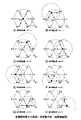
そして既存局同期区間では、中央制御局である識別ID♯0の通信局10では、図5のAに示すように、第0スロットの区間で、局同期信号の送信処理Txが行われ、その他のスロット(第1スロット以降の区間)では、受信処理が行われる。ここで、第6スロットまでの区間での受信では、それらのスロットに割当てられた通信局1〜6が、通信局10と直接的に無線通信できる位置にあるので、その受信信号に含まれるデータを正しくデコードできる。これに対して、第7スロットの区間では、通信局7が通信局10と直接的に無線通信できる位置にないので、このスロット位置ではデータの受信はできない。即ち、通信局10から第0スロットに送信される局同期信号の伝送状態を図6のAに示すと、通信局10から送信される信号の届く範囲内には、識別ID♯1〜♯6の通信局1〜6が位置し、通信局10からの局同期信号は、通信局1〜6で正しく受信されるが、離れた位置にある識別ID♯7の通信局7では、通信局10からの局同期信号は受信できない。
【0036】
識別ID♯1〜♯7の通信局1〜7では、図5のB〜Hに示すように、各通信局に割当てられたスロット位置で局同期信号を送信し、その他のスロット位置では受信処理を行う。即ち識別ID♯1の通信局1では、図5のBに示すように、第1スロットでノード同期信号の送信処理Txを行い、他のスロットで受信処理を行う。このとき、識別ID♯1の通信局1に隣接する位置の通信局は、識別ID♯0,♯2,♯4の通信局10,2,4であり、通信局1では、図5のBに示すように、これらのノードから第0スロット,第2スロット,第4スロットに送信されるノード同期信号だけを正しく受信処理できる。また、通信局1から第1スロットに送信される局同期信号の伝送状態を図6のBに示すと、通信局1から送信される信号の届く範囲内には、識別ID♯0,♯2,♯4の通信局10,2,4が位置し、通信局1からの局同期信号は、通信局2,4,10で正しく受信される。
【0037】
識別ID♯2の通信局2では、図5のCに示すように、第2スロットで局同期信号の送信処理Txを行い、他のスロットで受信処理を行う。このとき、通信局2に隣接する位置の通信局は、識別ID♯0,♯1,♯3の通信局10,1,3であり、通信局2では、図5のCに示すように、これらの通信局から第0スロット,第1スロット,第3スロットに送信される局同期信号だけを正しく受信処理できる。また、通信局2から第2スロットに送信される局同期信号の伝送状態を図6のCに示すと、通信局2から送信される信号の届く範囲内には、識別ID♯0,♯1,♯3の通信局10,1,3が位置し、通信局2からの局同期信号は、識別ID♯0,♯1,♯3の通信局10,1,3で正しく受信される。
【0038】
識別ID♯3の通信局3では、図5のDに示すように、第3スロットで局同期信号の送信処理Txを行い、他のスロットで受信処理を行う。このとき、通信局3に隣接する位置の通信局は、識別ID♯0,♯2,♯6,♯7の通信局10,2,6,7であり、通信局3では、図5のDに示すように、これらの通信局から第0スロット,第2スロット,第6スロット,第7スロットに送信される局同期信号だけを正しく受信処理できる。また、通信局3から第3スロットに送信される局同期信号の伝送状態を図6のDに示すと、通信局3から送信される信号の届く範囲内には、識別ID♯0,♯2,♯6,♯7の通信局10,2,6,7が位置し、通信局3からの局同期信号は、識別ID♯0,♯2,♯6,♯7の通信局10,2,6,7で正しく受信される。
【0039】
識別ID♯4の通信局4では、図5のEに示すように、第4スロットで局同期信号の送信処理Txを行い、他のスロットで受信処理を行う。このとき、通信局4に隣接する位置の通信局は、識別ID♯0,♯1,♯5の通信局10,1,5であり、通信局4では、図5のEに示すように、これらの通信局から第0スロット,第1スロット,第5スロットに送信される局同期信号だけを正しく受信処理できる。また、通信局4から第4スロットに送信される局同期信号の伝送状態を図6のEに示すと、通信局4から送信される信号の届く範囲内には、識別ID♯0,♯1,♯5の通信局10,1,5が位置し、通信局4からの局同期信号は、識別ID♯0,♯1,♯5の通信局10,1,5で正しく受信される。
【0040】
識別ID♯5の通信局5では、図5のFに示すように、第5スロットで局同期信号の送信処理Txを行い、他のスロットで受信処理を行う。このとき、通信局5に隣接する位置の通信局は、識別ID♯0,♯4,♯6の通信局10,4,6であり、通信局5では、図5のFに示すように、これらの通信局から第0スロット,第4スロット,第6スロットに送信される局同期信号だけを正しく受信処理できる。また、通信局5から第5スロットに送信される局同期信号の伝送状態を図6のFに示すと、通信局5から送信される信号の届く範囲内には、識別ID♯0,♯4,♯6の通信局10,4,6が位置し、通信局5からの局同期信号は、識別ID♯0,♯4,♯6の通信局10,4,6で正しく受信される。
【0041】
識別ID♯6の通信局6では、図5のGに示すように、第6スロットで局同期信号の送信処理Txを行い、他のスロットで受信処理を行う。このとき、通信局6に隣接する位置の通信局は、識別ID♯0,♯3,♯5,♯7の通信局10,3,5,7であり、通信局6では、図5のGに示すように、これらの通信局から第0スロット,第3スロット,第5スロット,第7スロットに送信される局同期信号だけを正しく受信処理できる。また、通信局6から第6スロットに送信される局同期信号の伝送状態を図6のGに示すと、通信局6から送信される信号の届く範囲内には、識別ID♯0,♯3,♯5,♯7の通信局10,3,5,7が位置し、通信局6からの局同期信号は、識別ID♯0,♯3,♯5,♯7の通信局10,3,5,7で正しく受信される。
【0042】
識別ID♯7の通信局7では、図5のHに示すように、第7スロットで局同期信号の送信処理Txを行い、他のスロットで受信処理を行う。このとき、通信局7に隣接する位置の通信局は、識別ID♯3,♯6の通信局3,6であり、通信局7では、図5のHに示すように、これらの通信局から第3スロット,第6スロットに送信される局同期信号だけを正しく受信処理できる。また、通信局7から第7スロットに送信される局同期信号の伝送状態を図6のHに示すと、通信局7から送信される信号の届く範囲内には、識別ID♯3,♯6の通信局3,6が位置し、通信局7からの局同期信号は、識別ID♯3,♯6の通信局3,6で正しく受信される。
【0043】
従って、中央制御局である通信局10では、識別ID♯7の通信局7からの局同期信号は受信できなく、直接的には通信局7の存在を認識することはできないが、識別ID♯3の通信局3からの局同期信号と、識別ID♯6の通信局6からの局同期信号に含まれる情報で、それぞれの局で受信できる局の情報から、中央制御局である通信局10が、通信局7の存在を認識する。ここでは、このように中央制御局と直接通信ができないネットワーク内の通信局を隠れ端末局と称する。
【0044】
また、中央制御局である通信局10からの信号を直接受信することができる通信局1〜6では、この通信局10からの局同期信号の受信タイミングを基準として、自局に割当てられた送信スロットの位置を判断する。そして、通信局10からの信号を直接受信できない通信局7では、その通信局7で受信できる局同期信号の受信タイミングを基準として、自局に割当てられた送信スロットの位置を判断する。即ち、第3スロットの位置と、第6スロットの位置から、自局に割当てられた第7スロットの位置を判断する処理を行う。
【0045】
次に、1フレーム内の局同期送受区間の新規参入区間のスロットを使用して、任意の通信局がこの通信ネットワークに新規参入する場合の処理を説明する。まず、ここまで説明した図1,図2に示すネットワーク構成の無線ネットワークに、1台の通信局を新規に参入させる要求があるとする。その新規に参入を希望する通信局は、ここでは無線ネットワーク内の他の通信局と基本的に同一の構成(即ち図3に示した構成)としてある。
【0046】
新規にネットワークに参入させる要求がある通信局では、まずその局が使用する周波数帯域の受信を行って、周辺に存在する通信局からの信号の受信を試みる。ここで、例えば中央制御局からの管理情報が受信できるとき、その管理情報により設定されるフレーム周期に同期させて、そのフレーム周期の局同期送受区間内の新規参入スロットに、新規参入を要求するデータを送信する。
【0047】
即ち、図7に示すように、局同期送受区間内の先頭部分に用意された1スロット期間の新規参入スロットで、新規参入を要求するデータの送信Txを行う。この図7の例は、図9のAに示すように、識別ID♯0の中央制御局と直接的に通信ができる範囲内に設置された通信局(ここでは識別IDが未定のため識別ID♯Xとしてある)から、新規参入スロットで新規参入を要求するデータを送信した例としてある。ここでの識別ID♯Xの通信局の周囲には、識別ID♯0,♯5,♯6の通信局が存在するため、識別ID♯Xの通信局では、新規参入スロットに続いた局同期送受区間内の対応したスロットで、それぞれの局からの局同期信号を受信する。この新規参入スロットで新規参入を要求するデータの送信は、例えば1フレーム期間だけ送信したり、或いは複数フレーム期間連続して送信するようにしても良い。
【0048】
このような新規参入スロットで伝送されるデータを、中央制御局が認識すると、管理情報同報区間に中央制御局から送信するデータ(又はメディア情報伝送領域で送信するデータ)で、中央制御局から新規参入の要求がある通信局に対して、この無線ネットワークに固有の情報(ここでは無線ネットワークのシステムID)を送信すると共に、その信号の送信元の通信局に対して固有の識別データ(ここでは通信局の識別ID)を付与して内部メモリ26に記憶させ、さらにその付与した識別データについても管理情報同報区間などで送信する。図9のBは、この中央制御局からの認証情報の送信状態を示したものである。新規参入の要求がある通信局では、これらのデータを受信すると、その受信したデータで示されるネットワークIDや局に固有の識別IDを、内部メモリ26に記憶させ、その記憶されたIDを自局のIDとして使用する。また、中央制御局では、以後は付与した識別IDでその通信局の認識を行う。
【0049】
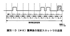
ここでは、新規参入要求があった通信局に対して識別ID♯8が付与されたものとする。この識別ID♯8を付与するデータが通信局で受信されて設定されることで、以後は図8に示すように、局同期送受区間内の識別ID♯8用のスロット位置で、その通信局から局同期信号の送信Txが行われ、無線ネットワーク内の端末局として機能する。この局同期送受区間内の識別ID♯8用のスロットは、局同期送受区間内に予め用意しておいても良いが、そのときの端末局の台数により中央制御局が可変設定し、1フレーム内の局同期送受区間以降の区間をメディア情報伝送領域とする構成としても良い。このように可変設定することで、そのときの端末局の台数に応じた適切な期間の局同期送受区間とメディア情報伝送領域とが設定され、1フレーム内でメディア情報伝送領域を最大限に有効利用できるようになる。
【0050】
なお、新規参入要求があった通信局が、中央制御局と直接通信ができるエリア内に存在する場合には、このように直接中央制御局に参入を要求することができるが、中央制御局と直接通信ができるエリア外の通信局が、その通信ネットワークの隠れ端末局(図1,図2のネットワークでの通信局7のような端末局)になることも可能である。以下、この隠れ端末局の場合の処理も含めた、新規参入要求を行う場合と、その新規参入要求を受信した側での処理を、フローチャートを参照して説明する。
【0051】
図10のフローチャートは、新規参入要求を行う端末局での処理を示したものである。まず、新規参入を行う場合には、自局に既に識別IDが付与されているか否か判断する(ステップS11)。ここで、まだ識別IDが付与されてない場合には、新規参入用のスロットを利用すると判断する(ステップS12)。また、以前に識別IDが付与されている場合には、その付与されたIDに割当てられた局同期送受区間内のスロットを使用すると判断する(ステップS13)。
【0052】
ステップS12,S13の処理が行われた後は、自局が隠れ端末局になるのか否か判断する(ステップS14)。この判断は、例えば中央制御局からの管理情報を直接的に受信できるか否かの判断に基づいて行う。中央制御局からの管理情報を直接的に受信できる場合には、隠れ端末局ではないと判断し、中央制御局からの管理情報を直接的に受信できない場合には、隠れ端末局であると判断する。
【0053】
ステップS14の判断で、自局が隠れ端末局になると判断したときには、中央制御局からの情報を中継できる親局を指定する(ステップS15)。このときには、そのときの受信状態や、受信した情報などに基づいて、最も確実に中継できる状態にある通信局を判断する。この判断としては、例えば最も受信レベルが高い通信局を判断したり、或いは局同期信号をある程度のレベル以上に良好に受信できる通信局の中から、移動できない状態に設定されているか等の判断を行って、中継できない状況になる可能性が少ない通信局を選択する。各通信局の移動可能性などの情報は、例えば各通信局からの局同期信号に含ませることで対処できる。
【0054】
ステップS14で自局が隠れ端末局でないと判断したとき、及びステップS15で親局を指定したとき、ここまでの判断で設定した状態で参入信号を送信する(ステップS16)。この参入を要求する信号は、識別IDがまだない局の場合(即ちステップS12の処理を行った場合)には、新規参入用スロットが送信に使用され、以前に識別IDが付与されている場合(即ちステップS13の処理を行った場合)には、その識別IDに対応したスロット位置が使用される。このように処理することで、新規参入する通信局では、そのときの状態に応じて適切な新規参入処理が行われる。
【0055】
次に、隠れ端末局が存在する可能性がある通信ネットワーク内での、各局での局同期送受区間での処理を図11のフローチャートに示す。まず局同期送受区間では、自局に割当てられたスロットで送信するタイミングであるか否か判断する(ステップS21)。ここで、自局に割当てられたスロット位置でないと判断した場合には、他局から送信される局同期情報を受信処理する(ステップS22)。そして、自局が隠れ端末局であるか否か判断し(ステップS23)、隠れ端末局である場合には、接続が確実な親局を指定する(ステップS24)。そして、他局からの局同期情報の受信状態に基づいて、自局の局同期情報を作成して記憶させておく(ステップS25)。自局が隠れ端末局である場合には、例えばこの局同期情報に親局を指定する情報を付加しておく。また、自局が隠れ端末局から親局と指定された局である場合には、自局が親局として指定されたことに関する情報と、その要求があった隠れ端末局に関する情報を、局同期情報に付加しておく。
【0056】
そして、ステップS21で自局が送信するタイミングであると判断したとき、ステップS25で作成して記憶された自局の局同期情報を読出し、その自局の局同期情報をネットワーク内に無線送信する(ステップS27)。
【0057】
次に、隠れ端末局が存在する可能性がある通信ネットワーク内での、各局での管理情報同報区間での処理を図12のフローチャートに示す。まず自局が中央制御局か否か判断する(ステップS31)。中央制御局であると判断したときには、管理情報同報区間内で制御局通知を送信する(ステップS32)。
【0058】
ステップS31で自局が中央制御局でないと判断したときには、制御局通知の受信処理を行い、各フレーム期間の管理情報同報区間内で制御局通知が受信できたか否か判断する(ステップS33)。管理情報同報区間内で制御局通知が全く受信できない場合には、処理を終了する。管理情報同報区間内で制御局通知が受信できた場合には、該当する制御局通知を保存させる(ステップS34)。そして、周辺局の局同期情報を獲得して(ステップS35)、周辺局から自局を親局として指定する情報があるか否か判断し(ステップS36)、親局として指定する情報がある場合には、制御局通知を中継送信する(ステップS37)。この制御局通知を中継送信するタイミングは、例えば予め管理情報同報区間内などに中継送信するためのタイミングが設定されている場合には、そのタイミングで送信する。或いは、メディア情報伝送領域内を使用して制御局通知を中継送信するようにしても良い。
【0059】
例えば、図1,図2に示したネットワーク構成で存在する隠れ端末局7に対する中継親局として、通信局3が指定されたときには、図13に示すように制御局通知の送受信処理が行われる。即ち、図13のA〜Hは、ネットワーク内の識別ID♯0〜♯7の8台の通信局での中央制御局からの制御局通知の送受信状態と、中継伝送用に用意された区間での送受信状態を示したものである。中央制御局からの制御局通知は、図13のAに示すように、識別ID♯0の中央制御局から送信Txが行われ、図13のB〜Gに示すように、隠れ端末局を除く各端末局で受信される。図14のAは、この制御局通知の伝送状態を示したものである。そして、中継親局として指定された識別ID♯3の端末局3では、図13のDに示すように、中継通知用に設定した区間で、直前に受信した制御局通知の送信Txが行われる。図14のBは、この中継通知される制御局通知の伝送状態を示したものであり、隠れ端末局7でも制御局通知が受信される。
【0060】
このように中継伝送を行う際の中継を行う局である親局の指定ができることで、ネットワーク内のどの端末局と通信ができる位置に存在する通信局であっても、隠れ端末局となってネットワークに参入することができる。このように中央制御局からの情報を直接受信できない隠れ端末局の存在を認めることにより、無線ネットワークの接続範囲を、中央制御局からの信号を受信できる範囲に限定することなく、より広範囲にすることができる。
【0061】
また、ネットワークを構成する局の存在を把握するために、各局毎に割当てられた局同期区間を設けて、中央制御局からの信号を直接受信することができない隠れ端末局も、ここでの情報送信を認めることによって、良好に無線ネットワークを広げることができる。
【0062】
ここで、ネットワークに新規参入する端末局のために、専用の新規参入用の伝送スロットを設ける構成としたことで、ネットワークに認証されていない端末局の参入を容易にすることができる。
【0063】
また、管理情報の伝送領域において、ネットワークを構成する全ての端末局による、局同期信号の送受する区間を、可変設定することで、1フレーム内のそれ以降の区間に用意されているメディア情報伝送領域を最大限に有効利用できるようになる。
【0064】
さらに、中央制御局からの信号を受信できない隠れ端末局が、隠れ端末局と確実に接続できる周辺局を親局として指定することによって、その中央制御局と通信を行う場合に、確実な中継伝送を行うことが可能になる。つまり、中央制御局からの情報を直接受信できない隠れ端末局においても、直接通信が可能である端末局(ブランチ局)を中継することで、このネットワークに新規参入して、中央制御局から送られてくるネットワーク共有の情報を確実に受信することができる。
【0065】
なお、上述した実施の形態で説明したフレーム構成や伝送データなどの例については、一例を示したものであり、上述した構成に限定されるものではない。また、無線伝送装置の構成についても、上述した例に限定されるものではなく、種々の無線伝送方式に適合した無線伝送装置で構成される通信ネットワークに、上述した通信制御処理を適用することが可能である。
【0066】
【発明の効果】
本発明の無線伝送方法によると、無線ネットワークに新規に参入したい局は、新規参入用に用意されたスロット位置で所定の信号を送信することで、他の通信局がその信号を認識して新規参入処理が実行され、新規参入用に予め設定された信号の送信を行うだけで簡単に任意の通信局を無線ネットワークに加入させることができる。
【0067】
また本発明の無線伝送方法によると、通信局がスロットで所定の信号の伝送を検出したとき、その信号の送信元の通信局に対して当該無線ネットワークに固有の情報を送信すると共に、その信号の送信元の通信局に対して固有の識別データを付与する処理を行うことで、その送信されたネットワークに固有の情報と付与された識別データを使用した参入処理が良好に行える。
【0068】
また本発明の無線伝送方法によると、識別データが付与された通信局は、信号を受信した通信局からの指示に基づいたフレーム周期内の所定のスロット位置で制御情報を送信することで、新規に参入された通信局での通信状態を中央制御局が正しく認識できるようになり、新規に参入された通信局の中央制御局での制御が良好に行える。
【0069】
また本発明の無線伝送方法によると、信号を受信した通信局以外の無線ネットワーク内の特定の通信局が新規参入用に用意されたスロットで所定の信号の伝送を検出し、信号を受信した通信局がそのスロットでの所定の信号の伝送を検出できないとき、所定の信号の送信元の通信局に対して、特定の通信局が中継局となって、無線ネットワークに参入させる処理を行うことで、直接的に通信ができない位置にある通信局を、無線ネットワークに加入させることが出来るようになる。
【0070】
また本発明の無線伝送方法によると、特定の通信局が複数存在するとき、所定の信号の送信元との通信状態が確実な通信局を中継局として選定することで、中央制御局と直接的に通信ができない位置にある通信局を無線ネットワークに加入させて通信させる際の通信状態が、常時良好な状態に維持される。
【0071】
また本発明の無線伝送方法によると、中継局として設定された通信局は、無線ネットワークで共有される管理情報を所定の信号の送信元の通信局に対して中継することで、中央制御局と直接的に通信ができない位置にある通信局が無線ネットワークに参入された場合に、その参入された局への管理情報の伝送が確実に行える。
【0072】
また本発明の無線伝送装置によると、所定スロット位置で特定の信号の受信を判別したとき、その特定の信号の送信元を無線ネットワークに参入させる処理が行われて、無線端末の新規参入がこの無線伝送装置の制御で実行され、新規参入用に予め設定された信号の所定スロット位置での判別を行うだけで、簡単にこの無線伝送装置の制御による新規参入処理の実行ができる。
【0073】
また本発明の無線伝送装置によると、制御手段は所定スロット位置の信号を判別したとき、その信号の送信元に対して固有の識別データを付与し、通信処理手段から識別データを送信させる制御を行うことで、新規に参入された無線端末に対する制御が、付与された識別データを使用して良好に行える。
【0074】
また本発明の無線伝送装置によると、制御手段は、送信元が制御情報を送信するスロット位置を指定する情報を、通信処理手段から送信させる制御を行うことで、新規に参入された無線端末で制御情報を送信するスロット位置の判断が行え、新規に参入された無線端末を含む無線ネットワークとして良好に構成される。
【0075】
また本発明の無線伝送装置によると、スロット位置での所定の信号を検出できない状態で通信処理手段が受信した制御情報の制御手段での判別で、無線ネットワークへの参入を希望する端末があることを認識したとき、制御手段は、通信処理手段から制御情報の送信元に対して無線ネットワークへの参入を指示する情報と、端末宛の情報の中継に関する情報とを送信させることで、新規に参入された無線端末の制御と、その参入された無線端末との中継を行う無線端末の設定とが行え、いわゆる隠れ端末をネットワーク内に新規参入させる処理が良好に行える。
【図面の簡単な説明】
【図1】本発明の一実施の形態によるネットワーク設定例を示す説明図である。
【図2】本発明の一実施の形態によるトポロジーマップの例を示す説明図である。
【図3】本発明の一実施の形態による無線伝送装置の構成を示すブロック図である。
【図4】本発明の一実施の形態によるフレーム構成例を示す説明図である。
【図5】本発明の一実施の形態による各ノードでの管理エリアでの伝送状態を示す説明図である。
【図6】本発明の一実施の形態による局間同期送受区間での送信/受信動作例を示す説明図である。
【図7】本発明の一実施の形態による新規参入スロットでの送信状態の例を示す説明図である。
【図8】本発明の一実施の形態による識別ID獲得後の送信状態の例を示す説明図である。
【図9】本発明の一実施の形態による新規参入局での送信/受信動作例を示す説明図である。
【図10】本発明の一実施の形態による新規参入局での処理例を示すフローチャートである。
【図11】本発明の一実施の形態による各局間同期送受区間での処理例を示すフローチャートである。
【図12】本発明の一実施の形態による管理情報同報区間での処理例を示すフローチャートである。
【図13】本発明の一実施の形態による管理情報の再送動作の処理例を示すタイミング図である。
【図14】本発明の一実施の形態による管理情報の再送状態の例を示す説明図である。
【符号の説明】
1〜8,10…無線伝送装置(ノード)、22…無線処理部、23…データ変換部、24…インターフェース部、25…制御部、26…内部メモリ[0001]
BACKGROUND OF THE INVENTION
The present invention relates to a radio transmission method suitable for application in a case where a local area network (LAN) is configured between a plurality of devices by transmitting various information by radio signals, for example, and radio transmission using the radio transmission method Relates to the device.
[0002]
[Prior art]
Conventionally, a local area network has been established so that data handled by various devices such as various video devices and personal computer devices and their peripheral devices can be transmitted within a relatively narrow range such as in a home or office. In the case of assembling, instead of directly connecting each device with a certain signal line, a wireless signal transmitting / receiving device (wireless transmission device) may be connected to each device to enable data transmission by wireless transmission.
[0003]
By configuring a local area network by wireless transmission, it is not necessary to connect each device directly with a signal line or the like, and the system configuration can be simplified.
[0004]
By the way, when a plurality of wireless transmission devices are prepared to form a local area network, a transmission error may occur if signals are simultaneously transmitted from the plurality of transmission devices. For this reason, it is necessary to control access between the transmission apparatuses in the network by some method.
[0005]
As a conventionally known access control method, for example, in a small-scale wireless network, each transmission device (terminal station: node) in a network is connected by a transmission device (central control station: root node) in a central part using star connection. ) There is a method for centrally managing communication. For example, there is a method for managing communication in a network by polling control. In this method, a central control station in the network transmits a control signal for polling in order to other nodes in the network, and transmission from each node is performed in order by polling. It is. By performing transmission processing by this polling, transmission efficiency can be improved.
[0006]
In the case of such a star-type network configuration, all communication stations in the network must be able to directly communicate with the central control station. A communication station that is relayed by a specific terminal station and cannot directly communicate with the central control station can function as a terminal station (so-called hidden terminal station) of this network.
[0007]
[Problems to be solved by the invention]
By the way, when such a wireless network is formed, for example, when the number of communication stations constituting the network is a predetermined number and all the communication stations used in the network are prepared in advance, this wireless network A unique identification ID, a unique terminal ID for each communication station, and the like can be set in advance at the time of manufacture of a transmission device constituting each communication station, at the time of network configuration, and the like. Can be done relatively easily.
[0008]
On the other hand, when a communication station is newly entered into an existing wireless network, it is necessary to set a communication network identification ID or terminal ID for the newly added communication station, which is troublesome. As a result, communication stations cannot be easily added. In addition to the settings such as IDs for these newly entered communication stations, the central control station managing the network also needs to recognize that there is a station that will be newly entered. Had a problem that the communication station could not be expanded.
[0009]
An object of the present invention is to make it easy to newly enter an existing wireless network.
[0010]
[Means for Solving the Problems]
The wireless transmission method of the present invention is a wireless transmission method in a wireless network composed of a plurality of communication stations. Based on reception of management information from surrounding communication stations While defining the frame period of the radio transmission signal, the predetermined position within the defined frame period, It is defined as a management information transmission area, and a plurality of slots are defined in the management information transmission area. Each communication station transmits management information in one of the slots, and a part of the slot is preliminarily set. Set as a slot for new entry into the wireless network, For new entrants slot Timing When there is a transmission of a predetermined signal, a process for causing the transmission source of the signal to enter the wireless network is performed.
[0011]
According to this wireless transmission method, a station that wishes to enter the wireless network so By synchronizing with the frame period and transmitting a predetermined signal at the slot position for new entry within the frame period, Other communication stations The new entry process is executed by recognizing the signal.
[0012]
According to another aspect of the present invention, there is provided a wireless transmission device that performs wireless communication with other communication stations in a wireless network, a communication processing unit that transmits and receives a wireless signal, and a signal that defines a frame period by the communication processing unit. And a control means for performing a process of causing the transmission source of the specific signal to enter the wireless network when it is determined to receive the specific signal at a predetermined slot position within the frame period.
[0013]
According to this wireless transmission device, when it is determined that a specific signal is received at a predetermined slot position, a process for causing the transmission source of the specific signal to enter the wireless network is performed, and a new entry of a wireless terminal is performed. It is executed under the control of
[0014]
DETAILED DESCRIPTION OF THE INVENTION
Hereinafter, an embodiment of the present invention will be described with reference to the accompanying drawings.
[0015]
In this example, the present invention is applied to a network system configured as a system for transmitting and receiving video data, audio data, computer data, etc. in a home or a relatively small office, for example. First, see FIG. The system configuration of this example will be described. In the network system of this example, the maximum number of wireless transmission devices constituting the network is determined in advance. For example, the network is formed by a maximum of 16 wireless transmission devices, and FIG. The state which has arrange | positioned the transmission apparatuses 1-7, 10 is shown. Each of the
[0016]
The eight
[0017]
In this case, a system configuration in which any one wireless transmission device in the network system is set as a root node functioning as a central control station, and wireless communication between the nodes is executed by polling control from the control station. It is as. Ideally, this control station basically uses a radio transmission apparatus arranged at a position where radio communication can be performed directly with all other communication stations in the system. Here, the
[0018]
Here, in this example, the
[0019]
FIG. 2 is a diagram showing a physical topology map showing a communication state between stations in the arrangement state of each communication station and control station in this example, and is directly connected between communication stations connected by arrows. Is ready to communicate. An area a indicated by a broken line in FIG. 2 is a range in which wireless communication can be performed directly with the
[0020]
FIG. 3 shows a configuration example of the
[0021]
Then, a
[0022]
Each unit in the wireless transmission device is configured to execute processing based on the control of the
[0023]
FIG. 4 shows the configuration of signals transmitted between the communication stations (
[0024]
In the management information broadcast section, management information common to the system is transmitted from the
[0025]
In the existing station synchronization section of the station synchronization transmission / reception section in one frame, a predetermined number (16 in this case) of slots is set at equal intervals, and 16 slots in this one frame are 16 communications in this network system. Assigned to each station. As the slot allocation, for example, a communication station slot with
[0026]
The station synchronization signal transmitted in each slot of the station synchronization transmission / reception section is received and processed by each communication station in the network system. The station synchronization signal transmission processing and reception processing will be described later.
[0027]
In the media information transmission area, data transfer (transmission) processing is performed between the communication stations based on access control of the central control station. The access control by the central control station is executed by polling control from the central control station, for example. In this polling control process, each communication station is sequentially called by a polling response request signal from the central control station, and transmission is sequentially executed for each communication station.
[0028]
Then, when there is data to be transmitted, the communication station having the identification ID specified by the polling response request signal immediately performs data transmission processing when receiving the polling response request signal.
[0029]
Note that data transmission in the media information transmission area is not transmission by such polling, but the media information transmission area of one frame is divided into a plurality of slots in advance, and the divided slots are assigned to the central control station. Wireless transmission may be performed by assigning to a communication station having a transmission request under control.
[0030]
As the transmission processing at this time, for example, data transfer in the asynchronous transfer mode and data transfer in the isochronous transfer mode may be used depending on the type of data to be transmitted. Asynchronous transfer mode and isochronous transfer mode are used for transmission of relatively short data such as control data, for example, and isochronous transfer mode is used for transmission of data requiring real-time transfer such as video data and audio data. used. As a transmission control method in which such a transmission mode is prepared, for example, a method defined as the IEEE 1394 standard can be applied.
[0031]
As the asynchronous transfer mode, for example, it is preferable to use a transmission method by polling control, and as the isochronous transfer mode, for example, to perform assignment transmission by slot division.
[0032]
Next, transmission processing and reception processing of the station synchronization signal will be described with reference to FIG. As described above, 16 slots are prepared in the existing station synchronization section of the station synchronization transmission / reception section in one frame, but here, in order to simplify the description, eight slots from the 0th slot to the seventh slot are prepared. Are prepared, and each slot is individually assigned to each of the
[0033]
5A to 5H show the communication state in the station synchronous transmission / reception section of the eight communication stations, and FIG. 5A shows the state in the
[0034]
First, since eight communication stations are already set as communication stations for a wireless network that performs communication under the control of the
[0035]
Then, in the existing station synchronization section, the
[0036]
In
[0037]
In the
[0038]
In the
[0039]
In the
[0040]
In the
[0041]
In the
[0042]
In the
[0043]
Accordingly, the
[0044]
Further, in the
[0045]
Next, processing when an arbitrary communication station newly enters the communication network using the slot of the new entry section of the station synchronous transmission / reception section within one frame will be described. First, it is assumed that there is a request to newly enter one communication station in the wireless network having the network configuration shown in FIGS. Here, the communication station that wishes to newly enter has basically the same configuration as the other communication stations in the wireless network (that is, the configuration shown in FIG. 3).
[0046]
A communication station that is newly requested to enter the network first receives the frequency band used by the station and tries to receive signals from communication stations existing in the vicinity. Here, for example, when management information from the central control station can be received, a new entry is requested to a new entry slot in the station synchronization transmission / reception section of the frame period in synchronization with the frame period set by the management information. Send data.
[0047]
That is, as shown in FIG. 7, transmission Tx of data requesting new entry is performed in a new entry slot of one slot period prepared at the head part in the station synchronous transmission / reception section. In the example of FIG. 7, as shown in FIG. 9A, a communication station installed within a range where it can communicate directly with the central control station of the identification ID # 0 (here, the identification ID is undecided because the identification ID is not yet determined). This is an example in which data for requesting a new entry is transmitted from a new entry slot. Since communication stations with
[0048]
When the central control station recognizes data transmitted in such a new entry slot, the data transmitted from the central control station in the management information broadcast section (or data transmitted in the media information transmission area), from the central control station Information specific to this wireless network (here, the system ID of the wireless network) is transmitted to a communication station that has a request for new entry, and identification data unique to the communication station that transmitted the signal (here) Then, the identification ID of the communication station is assigned and stored in the
[0049]
Here, it is assumed that
[0050]
In addition, when the communication station that has requested new entry exists in an area that can communicate directly with the central control station, it is possible to request entry directly to the central control station in this way. A communication station outside the area capable of direct communication can be a hidden terminal station of the communication network (a terminal station such as the
[0051]
The flowchart of FIG. 10 shows processing at a terminal station that makes a new entry request. First, when a new entry is made, it is determined whether an identification ID has already been assigned to the own station (step S11). Here, when the identification ID has not been given yet, it is determined to use the slot for new entry (step S12). If an identification ID has been previously assigned, it is determined that the slot in the station synchronization transmission / reception section assigned to the assigned ID is to be used (step S13).
[0052]
After the processes of steps S12 and S13 are performed, it is determined whether or not the own station becomes a hidden terminal station (step S14). This determination is made based on, for example, determination whether or not management information from the central control station can be received directly. If the management information from the central control station can be received directly, it is determined not to be a hidden terminal station, and if the management information from the central control station cannot be received directly, it is determined to be a hidden terminal station. To do.
[0053]
If it is determined in step S14 that the local station is a hidden terminal station, a master station capable of relaying information from the central control station is designated (step S15). At this time, based on the reception state at that time, the received information, etc., the communication station that is in a state that can be relayed most reliably is determined. As this determination, for example, a communication station having the highest reception level is determined, or a determination is made as to whether or not the mobile station is set in a state in which it cannot move from among communication stations that can successfully receive a station synchronization signal at a certain level or higher. Go to select a communication station that is unlikely to relay. Information such as the mobility of each communication station can be dealt with by including it in a station synchronization signal from each communication station, for example.
[0054]
When it is determined in step S14 that the local station is not a hidden terminal station, or when a master station is designated in step S15, an entry signal is transmitted in the state set by the determination so far (step S16). In the case of a station that does not yet have an identification ID (that is, when the process of step S12 is performed), a signal for requesting entry is used for transmission and a slot for new entry has been assigned before. In other words, when the process of step S13 is performed, the slot position corresponding to the identification ID is used. By processing in this way, in the newly entering communication station, appropriate new entry processing is performed according to the state at that time.
[0055]
Next, the process in the station synchronous transmission / reception section in each station in the communication network where there is a possibility that the hidden terminal station exists is shown in the flowchart of FIG. First, in the station synchronous transmission / reception section, it is determined whether or not it is time to transmit in the slot allocated to the own station (step S21). If it is determined that the slot position is not allocated to the own station, the station synchronization information transmitted from the other station is received (step S22). Then, it is determined whether or not the own station is a hidden terminal station (step S23). If the own station is a hidden terminal station, a parent station that is surely connected is designated (step S24). Based on the reception state of the station synchronization information from the other station, the station synchronization information of the own station is created and stored (step S25). If the own station is a hidden terminal station, for example, information specifying the parent station is added to the station synchronization information. In addition, if the local station is a station designated as a master station by a hidden terminal station, information on the fact that the local station has been designated as the master station and information on the hidden terminal station that requested that station are synchronized. It is added to the information.
[0056]
When it is determined in step S21 that it is the transmission timing of the own station, the station synchronization information of the own station created and stored in step S25 is read, and the station synchronization information of the own station is wirelessly transmitted in the network. (Step S27).
[0057]
Next, the processing in the management information broadcast section in each station in the communication network where there is a possibility that the hidden terminal station exists is shown in the flowchart of FIG. First, it is determined whether or not the own station is a central control station (step S31). If it is determined that it is a central control station, a control station notification is transmitted within the management information broadcast section (step S32).
[0058]
When it is determined in step S31 that the own station is not a central control station, a control station notification reception process is performed to determine whether or not a control station notification has been received within the management information broadcast section of each frame period (step S33). . If no control station notification can be received within the management information broadcast section, the process ends. If the control station notification can be received within the management information broadcast section, the corresponding control station notification is stored (step S34). Then, the station synchronization information of the peripheral station is acquired (step S35), and it is determined whether there is information specifying the own station as the parent station from the peripheral station (step S36). The control station notification is relayed and transmitted (step S37). For example, when the timing for relay transmission of the control station notification is set in advance in, for example, the management information broadcast section, it is transmitted at that timing. Alternatively, the control station notification may be relayed and transmitted using the media information transmission area.
[0059]
For example, when the
[0060]
In this way, by specifying a master station that is a station that performs relay transmission, even a communication station that exists in a position where communication with any terminal station in the network can be performed is a hidden terminal station. Can enter the network. By recognizing the existence of hidden terminal stations that cannot directly receive information from the central control station in this way, the wireless network connection range is made wider without limiting to the range in which signals from the central control station can be received. be able to.
[0061]
In addition, in order to grasp the existence of the stations that make up the network, hidden terminal stations that are not able to directly receive signals from the central control station by providing station synchronization sections assigned to each station are also included here. By allowing transmission, the wireless network can be expanded well.
[0062]
Here, for a terminal station that newly enters the network, a dedicated new entry transmission slot is provided, thereby facilitating entry of terminal stations that are not authenticated to the network.
[0063]
In addition, in the management information transmission area, media information transmission prepared for the subsequent sections in one frame can be set by variably setting the section for transmitting and receiving the station synchronization signal by all terminal stations constituting the network. The area can be used to the maximum extent possible.
[0064]
In addition, when a hidden terminal station that cannot receive a signal from the central control station designates a peripheral station that can be reliably connected to the hidden terminal station as a master station, reliable relay transmission is possible when communicating with the central control station. It becomes possible to do. In other words, even in a hidden terminal station that cannot directly receive information from the central control station, the terminal station (branch station) capable of direct communication can be relayed to newly enter this network and sent from the central control station. It is possible to reliably receive incoming network sharing information.
[0065]
Note that examples of the frame configuration, transmission data, and the like described in the above-described embodiment are merely examples, and are not limited to the above-described configuration. In addition, the configuration of the wireless transmission device is not limited to the above-described example, and the above-described communication control processing may be applied to a communication network including wireless transmission devices that are compatible with various wireless transmission schemes. Is possible.
[0066]
【The invention's effect】
Of the present invention According to the wireless transmission method, a station that wants to newly enter the wireless network transmits a predetermined signal at the slot position prepared for new entry, Other communication stations A new entry process is executed by recognizing the signal, and an arbitrary communication station can be easily joined to the wireless network simply by transmitting a signal preset for new entry.
[0067]
The present invention According to the wireless transmission method ,communication When a station detects transmission of a predetermined signal in a slot, it transmits information specific to the wireless network to the communication station that transmitted the signal, and is specific to the communication station that transmitted the signal. By performing the process of giving the identification data, the entry process using the information unique to the transmitted network and the given identification data can be performed satisfactorily.
[0068]
The present invention According to the wireless transmission method , The communication station with the identification data is The communication station that received the signal By transmitting control information at a predetermined slot position within the frame period based on the instruction from the central control station, the central control station can correctly recognize the communication status at the newly entered communication station, and newly entered The central control station of the communication station can be controlled well.
[0069]
The present invention According to the wireless transmission method The communication station that received the signal A specific communication station in a wireless network other than the Detects transmission of a predetermined signal in a slot prepared for new entry, The communication station that received the signal Is unable to detect the transmission of a given signal in that slot, But By becoming a relay station and processing to enter the wireless network ,straight A communication station in a position where it cannot communicate directly can be joined to the wireless network.
[0070]
The present invention According to the wireless transmission method , When there are multiple specific communication stations, select a communication station that has a reliable communication status with the transmission source of a predetermined signal as a relay station, so that a communication station that cannot communicate directly with the central control station is selected. The communication state at the time of making it join and communicate with a wireless network is always maintained in a favorable state.
[0071]
The present invention According to the wireless transmission method , A communication station set as a relay station relays management information shared by a wireless network to a communication station that is a transmission source of a predetermined signal, so that communication at a position where it cannot communicate directly with the central control station. When a station enters a wireless network, management information can be reliably transmitted to the station that has joined the station.
[0072]
The present invention According to the wireless transmission device, when the reception of a specific signal is determined at a predetermined slot position, a process of causing the transmission source of the specific signal to enter the wireless network is performed, and a new entry of a wireless terminal is performed by the wireless transmission device. The new entry process can be easily executed by the control of the wireless transmission device only by determining at a predetermined slot position of a signal that is executed under control and preset for new entry.
[0073]
The present invention According to the wireless transmission device , When the control means discriminates the signal at the predetermined slot position, the control means assigns unique identification data to the transmission source of the signal, and performs control to transmit the identification data from the communication processing means, thereby newly entering the wireless Control over the terminal can be satisfactorily performed using the assigned identification data.
[0074]
The present invention According to the wireless transmission device , The control means performs control for transmitting from the communication processing means information specifying the slot position at which the transmission source transmits the control information, so that the newly determined wireless terminal can determine the slot position at which the control information is transmitted. It can be performed and is well configured as a wireless network including newly entered wireless terminals.
[0075]
The present invention According to the wireless transmission device , When the control means recognizes that there is a terminal that wishes to join the wireless network in the determination of the control information received by the communication processing means when the predetermined signal at the slot position cannot be detected, the control means Control of the newly entered wireless terminal and its entry by causing the processing means to send information instructing the transmission source of the control information to enter the wireless network and information related to relaying information addressed to the terminal. It is possible to set a wireless terminal that relays to the wireless terminal, and to perform a process of newly entering a so-called hidden terminal in the network.
[Brief description of the drawings]
FIG. 1 is an explanatory diagram showing a network setting example according to an embodiment of the present invention.
FIG. 2 is an explanatory diagram showing an example of a topology map according to an embodiment of the present invention.
FIG. 3 is a block diagram showing a configuration of a wireless transmission device according to an embodiment of the present invention.
FIG. 4 is an explanatory diagram showing an example of a frame configuration according to an embodiment of the present invention.
FIG. 5 is an explanatory diagram showing a transmission state in a management area in each node according to an embodiment of the present invention.
FIG. 6 is an explanatory diagram showing an example of transmission / reception operation in the inter-station synchronous transmission / reception section according to the embodiment of the present invention.
FIG. 7 is an explanatory diagram showing an example of a transmission state in a new entry slot according to an embodiment of the present invention.
FIG. 8 is an explanatory diagram showing an example of a transmission state after obtaining an identification ID according to an embodiment of the present invention.
FIG. 9 is an explanatory diagram showing an example of transmission / reception operation in a new entry station according to an embodiment of the present invention.
FIG. 10 is a flowchart showing an example of processing in a new entry station according to an embodiment of the present invention.
FIG. 11 is a flowchart showing an example of processing in the inter-station synchronous transmission / reception section according to the embodiment of the present invention.
FIG. 12 is a flowchart showing a processing example in a management information broadcast section according to the embodiment of the present invention.
FIG. 13 is a timing diagram showing a processing example of a management information retransmission operation according to an embodiment of the present invention;
FIG. 14 is an explanatory diagram showing an example of a retransmission state of management information according to an embodiment of the present invention.
[Explanation of symbols]
DESCRIPTION OF SYMBOLS 1-8,10 ... Wireless transmission apparatus (node), 22 ... Wireless processing part, 23 ... Data conversion part, 24 ... Interface part, 25 ... Control part, 26 ... Internal memory
Claims (10)
上記通信局が周囲の通信局からの管理情報の受信に基づいて無線伝送信号のフレーム周期を規定すると共に、その規定したフレーム周期内の所定の位置を、管理情報伝送領域として規定し、
さらに上記管理情報伝送領域に複数のスロットを規定し、各通信局がそのスロットの1つで管理情報を送信すると共に、予めそのスロットの一部を上記無線ネットワークへの新規参入用のスロットとして設定し、
上記新規参入用のスロットのタイミングで所定の信号の伝送があるとき、その信号の送信元を無線ネットワークに参入させる処理を行う無線伝送方法。In a wireless transmission method in a wireless network composed of a plurality of communication stations,
The communication station defines the frame period of the radio transmission signal based on reception of management information from surrounding communication stations, and defines a predetermined position within the defined frame period as a management information transmission area,
Furthermore, a plurality of slots are defined in the management information transmission area, and each communication station transmits management information in one of the slots, and a part of the slots is set in advance as a slot for new entry into the wireless network. And
A wireless transmission method for performing a process of causing a transmission source of a signal to enter a wireless network when a predetermined signal is transmitted at the timing of the new entry slot.
上記通信局の内、ネットワークを管理する特定の通信局が上記新規参入用のスロットで所定の信号の伝送を検出したとき、
その信号の送信元の通信局に対して当該無線ネットワークに固有の情報を送信すると共に、
管理情報伝送領域のスロットの1つで管理情報を送信するためにその信号の送信元の通信局に対して固有の識別データを付与する処理を行う無線伝送方法。The wireless transmission method according to claim 1,
Among the communication stations , when a specific communication station that manages the network detects transmission of a predetermined signal in the new entry slot,
While transmitting information specific to the wireless network to the communication station that sent the signal,
A wireless transmission method for performing a process of giving unique identification data to a communication station that is a transmission source of a signal in order to transmit management information in one of the slots of the management information transmission area .
上記識別データが付与された通信局は、上記信号を受信した通信局からの指示に基づいた上記フレーム周期内の管理情報伝送領域における所定のスロット位置で上記管理情報伝送領域における周囲の通信局からの管理情報の受信状況を示す管理情報を送信する無線伝送方法。The wireless transmission method according to claim 2,
The communication station to which the identification data is given is transmitted from surrounding communication stations in the management information transmission region at a predetermined slot position in the management information transmission region within the frame period based on an instruction from the communication station that has received the signal. Wireless transmission method for transmitting management information indicating a reception status of management information.
上記管理情報伝送領域における周囲の通信局からの管理情報の受信に基づいて、ネットワークを管理する特定の通信局からの管理情報を受信できないものの、上記特定の通信局の管理情報を検出している周囲の通信局が存在する場合に、上記周囲の通信局を中継局として指定することで、無線ネットワークに参入させる処理を行う無線伝送方法。The wireless transmission method according to claim 1,
Based on reception of management information from surrounding communication stations in the management information transmission area, management information of the specific communication station is detected although management information from the specific communication station managing the network cannot be received. A wireless transmission method for performing a process of entering a wireless network by designating the surrounding communication station as a relay station when surrounding communication stations exist .
上記特定の通信局を検出している周囲の通信局が複数存在するとき、上記周囲の通信局のうち、新規に無線ネットワークに参入する送信元との通信状態が確実な通信局を上記中継局として選定する無線伝送方法。The wireless transmission method according to claim 4, wherein
When there are a plurality of surrounding communication stations that detect the specific communication station, among the surrounding communication stations, a communication station that is surely in communication with a transmission source that newly enters the wireless network is selected as the relay station. Wireless transmission method to select as.
上記中継局として設定された通信局は、無線ネットワークで共有される管理情報を上記所定の信号の送信元の通信局に対して中継する無線伝送方法。The wireless transmission method according to claim 4, wherein
A wireless transmission method in which a communication station set as the relay station relays management information shared in a wireless network to a communication station that is a transmission source of the predetermined signal.
無線信号の送信及び受信を行う無線処理手段と、
周囲の通信局からの管理情報に基づいて、上記無線処理手段で受信した所定のフレーム周期を設定すると共に、その規定したフレーム周期内の所定の位置を管理情報伝送領域とし、上記管理情報伝送領域に複数のスロットを規定し、各通信局がそのスロットの1つで管理情報を送信させると共に、予めそのスロットの一部を新規参入スロットと規定し、
所定の新規参入スロット位置での特定の信号を判別したとき、上記特定の信号の送信元を無線ネットワークに参入させる処理を行う制御手段とを備えた
無線伝送装置。In a wireless transmission device that performs wireless communication with other communication stations in a wireless network,
Wireless processing means for transmitting and receiving wireless signals;
Based on the management information from the surrounding communication stations, the predetermined frame period received by the wireless processing means is set , the predetermined position within the defined frame period is set as the management information transmission area, and the management information transmission area A plurality of slots, and each communication station transmits management information in one of the slots, and a part of the slot is defined as a new entry slot in advance,
A wireless transmission device comprising: control means for performing processing for causing a transmission source of the specific signal to enter a wireless network when a specific signal at a predetermined new entry slot position is determined.
上記制御手段は、上記新規参入スロット位置の信号を判別したとき、その信号の送信元に対して管理情報伝送領域のスロットの1つで管理情報を送信するために固有の識別データを付与し、上記通信処理手段から上記識別データを送信させる制御を行う
無線伝送装置。Among the wireless transmission devices according to claim 7 , in the case of a specific communication station that manages a network ,
When the control means determines the signal of the new entry slot position, it gives unique identification data to transmit the management information in one of the slots of the management information transmission area to the transmission source of the signal, A radio transmission apparatus that performs control to transmit the identification data from the communication processing means.
上記制御手段は、上記送信元が上記管理情報伝送領域における周囲の通信局からの管理情報の受信状況を示す管理情報を送信するスロット位置を指定する情報を、上記通信処理手段から送信させる制御を行う、
無線伝送装置。The wireless transmission device according to claim 8, wherein
The control means controls the transmission processing means to transmit information designating a slot position for transmitting management information indicating the reception status of management information from surrounding communication stations in the management information transmission area. Do,
Wireless transmission device.
上記管理情報伝送領域における周囲の通信局からの管理情報の受信に基づいて、ネットワークを管理する特定の通信局からの管理情報を受信できないものの、上記特定の通信局の管理情報を検出している周囲の通信局が存在する場合に、上記周囲の通信局を中継局として指定する情報とを送信させる
無線伝送装置。The wireless transmission device according to claim 7, wherein
Based on reception of management information from surrounding communication stations in the management information transmission area, management information of the specific communication station is detected although management information from the specific communication station managing the network cannot be received. A wireless transmission device that transmits information specifying a surrounding communication station as a relay station when a surrounding communication station exists .
Priority Applications (5)
| Application Number | Priority Date | Filing Date | Title |
|---|---|---|---|
| JP08010099A JP4192328B2 (en) | 1999-03-24 | 1999-03-24 | Wireless transmission method and wireless transmission device |
| EP00302355A EP1039696B1 (en) | 1999-03-24 | 2000-03-22 | Radio transmission in a local area network |
| DE60011689T DE60011689T2 (en) | 1999-03-24 | 2000-03-22 | Radio communication in a local network |
| US09/533,082 US6728231B1 (en) | 1999-03-24 | 2000-03-22 | Radio transmission method and radio transmission |
| KR1020000014555A KR20000071467A (en) | 1999-03-24 | 2000-03-22 | Radio transmission method and radio transmission apparatus |
Applications Claiming Priority (1)
| Application Number | Priority Date | Filing Date | Title |
|---|---|---|---|
| JP08010099A JP4192328B2 (en) | 1999-03-24 | 1999-03-24 | Wireless transmission method and wireless transmission device |
Publications (3)
| Publication Number | Publication Date |
|---|---|
| JP2000278280A JP2000278280A (en) | 2000-10-06 |
| JP2000278280A5 JP2000278280A5 (en) | 2006-06-08 |
| JP4192328B2 true JP4192328B2 (en) | 2008-12-10 |
Family
ID=13708776
Family Applications (1)
| Application Number | Title | Priority Date | Filing Date |
|---|---|---|---|
| JP08010099A Expired - Lifetime JP4192328B2 (en) | 1999-03-24 | 1999-03-24 | Wireless transmission method and wireless transmission device |
Country Status (5)
| Country | Link |
|---|---|
| US (1) | US6728231B1 (en) |
| EP (1) | EP1039696B1 (en) |
| JP (1) | JP4192328B2 (en) |
| KR (1) | KR20000071467A (en) |
| DE (1) | DE60011689T2 (en) |
Cited By (4)
| Publication number | Priority date | Publication date | Assignee | Title |
|---|---|---|---|---|
| WO2010082388A1 (en) | 2009-01-19 | 2010-07-22 | シャープ株式会社 | Synchronization device and radio transmission system |
| WO2010106705A1 (en) | 2009-03-16 | 2010-09-23 | シャープ株式会社 | Radio transmission system, relay device, radio synchronization device, and radio source device |
| JP2011019262A (en) * | 2010-08-19 | 2011-01-27 | Sharp Corp | Radio transmission system |
| WO2011122456A1 (en) | 2010-03-29 | 2011-10-06 | シャープ株式会社 | Sink device, source device and wireless transmission system |
Families Citing this family (13)
| Publication number | Priority date | Publication date | Assignee | Title |
|---|---|---|---|---|
| JP3796537B2 (en) | 2000-10-24 | 2006-07-12 | 独立行政法人情報通信研究機構 | Wireless communication terminal, wireless communication method, and information recording medium |
| KR100395349B1 (en) * | 2001-07-30 | 2003-08-21 | 안남진 | multi-video data transmission system |
| US20030068975A1 (en) * | 2001-08-06 | 2003-04-10 | The Research Foundation Of Suny | Integrated cellular and ad hoc relaying system |
| JP2003143056A (en) * | 2001-11-05 | 2003-05-16 | Uniden Corp | Radio terminal, radio synchronization system having no reference station, and program therefor |
| JP3876752B2 (en) | 2002-04-15 | 2007-02-07 | ソニー株式会社 | COMMUNICATION SYSTEM, COMMUNICATION CONTROL DEVICE, COMMUNICATION CONTROL METHOD, AND COMPUTER PROGRAM |
| JP2003318917A (en) * | 2002-04-26 | 2003-11-07 | Sony Corp | Wireless communication system, wireless communication terminal, and method for participating in wireless communication system |
| US7444152B2 (en) * | 2002-06-28 | 2008-10-28 | Nokia Corporation | Signaling and routing protocols for an integrated cellular and relaying system |
| US7720471B2 (en) * | 2005-07-27 | 2010-05-18 | Sharp Laboratories Of America | Method for managing hidden stations in a centrally controlled network |
| JP4678859B2 (en) * | 2006-01-12 | 2011-04-27 | キヤノン株式会社 | COMMUNICATION DEVICE AND ITS CONTROL METHOD |
| US8571473B2 (en) | 2006-06-02 | 2013-10-29 | Qualcomm Incorporated | Wireless subscriber station for short range ad-hoc data communication |
| JP2008219498A (en) * | 2007-03-05 | 2008-09-18 | Oki Electric Ind Co Ltd | Relay communicating system |
| EP3264685B1 (en) | 2008-12-12 | 2019-03-06 | Mitsubishi Electric Corporation | Data transmitting and receiving method, data transmitting and receiving system, master device, and slave device |
| JP5676911B2 (en) * | 2010-04-30 | 2015-02-25 | キヤノン株式会社 | COMMUNICATION SYSTEM, CONTROL NODE DEVICE, ITS CONTROL METHOD, CONTROLLED NODE DEVICE, ITS CONTROL METHOD, PROGRAM |
Family Cites Families (15)
| Publication number | Priority date | Publication date | Assignee | Title |
|---|---|---|---|---|
| US4549293A (en) * | 1983-12-29 | 1985-10-22 | The United States Of America As Represented By The Secretary Of The Army | Time division multiple access communications system |
| DE3527330A1 (en) * | 1985-07-31 | 1987-02-05 | Philips Patentverwaltung | DIGITAL RADIO TRANSMISSION SYSTEM WITH CONNECTING ORGANIZATION CHANNEL IN THE TIME MULTIPLEX FRAME |
| JPH0748742B2 (en) * | 1987-07-15 | 1995-05-24 | 株式会社日立製作所 | Multi-slot access method |
| CA2001339C (en) | 1988-12-02 | 1993-12-21 | Jaime Andres Borras | Repeater for a controlled radio system |
| JP3212169B2 (en) * | 1993-01-06 | 2001-09-25 | 株式会社東芝 | Wireless communication system and base station |
| US5553076A (en) * | 1994-05-02 | 1996-09-03 | Tcsi Corporation | Method and apparatus for a wireless local area network |
| GB2291564B (en) * | 1994-07-13 | 1999-02-10 | Nec Corp | Mobile communication for a mobile station near the boundary of or outside a service area of a base station |
| US5612948A (en) | 1994-11-18 | 1997-03-18 | Motorola, Inc. | High bandwidth communication network and method |
| JP3052828B2 (en) * | 1996-02-26 | 2000-06-19 | 日本電気株式会社 | Multi-way time division multiplex wireless data communication method |
| JP4048588B2 (en) * | 1998-02-27 | 2008-02-20 | ソニー株式会社 | Polling control method and transmission control device |
| JP2000092077A (en) * | 1998-09-11 | 2000-03-31 | Sony Corp | Communication control method and transmitter |
| JP2000092076A (en) * | 1998-09-11 | 2000-03-31 | Sony Corp | Communication control method and transmitter |
| JP2000101495A (en) * | 1998-09-18 | 2000-04-07 | Sony Corp | Communication control method and transmission device |
| JP2000165364A (en) * | 1998-11-30 | 2000-06-16 | Sony Corp | Radio network and method for time synchronization establishment among a plurality of buses |
| WO2000042737A1 (en) | 1999-01-13 | 2000-07-20 | Koninklijke Philips Electronics N.V. | A wireless local area network(lan) and a method of operating the lan |
-
1999
- 1999-03-24 JP JP08010099A patent/JP4192328B2/en not_active Expired - Lifetime
-
2000
- 2000-03-22 EP EP00302355A patent/EP1039696B1/en not_active Expired - Lifetime
- 2000-03-22 DE DE60011689T patent/DE60011689T2/en not_active Expired - Lifetime
- 2000-03-22 KR KR1020000014555A patent/KR20000071467A/en not_active Application Discontinuation
- 2000-03-22 US US09/533,082 patent/US6728231B1/en not_active Expired - Lifetime
Cited By (10)
| Publication number | Priority date | Publication date | Assignee | Title |
|---|---|---|---|---|
| WO2010082388A1 (en) | 2009-01-19 | 2010-07-22 | シャープ株式会社 | Synchronization device and radio transmission system |
| US8982760B2 (en) | 2009-01-19 | 2015-03-17 | Sharp Kabushiki Kaisha | Sink device and wireless transmission system |
| WO2010106705A1 (en) | 2009-03-16 | 2010-09-23 | シャープ株式会社 | Radio transmission system, relay device, radio synchronization device, and radio source device |
| US8613029B2 (en) | 2009-03-16 | 2013-12-17 | Sharp Kabushiki Kaisha | Wireless transmission system, relay device, wireless sink device, and wireless source device |
| US8898710B2 (en) | 2009-03-16 | 2014-11-25 | Sharp Kabushiki Kaisha | Wireless transmission system, relay device, wireless sink device, and wireless source device |
| US9161097B2 (en) | 2009-03-16 | 2015-10-13 | Sharp Kabushiki Kaisha | Wireless transmission system, relay device, wireless sink device, and wireless source device |
| US9161096B2 (en) | 2009-03-16 | 2015-10-13 | Sharp Kabushiki Kaisha | Wireless transmission system, relay device, wireless sink device, and wireless source device |
| WO2011122456A1 (en) | 2010-03-29 | 2011-10-06 | シャープ株式会社 | Sink device, source device and wireless transmission system |
| US8745285B2 (en) | 2010-03-29 | 2014-06-03 | Sharp Kabushiki Kaisha | Sink device, source device and wireless transmission system |
| JP2011019262A (en) * | 2010-08-19 | 2011-01-27 | Sharp Corp | Radio transmission system |
Also Published As
| Publication number | Publication date |
|---|---|
| EP1039696A3 (en) | 2002-09-11 |
| JP2000278280A (en) | 2000-10-06 |
| EP1039696B1 (en) | 2004-06-23 |
| DE60011689D1 (en) | 2004-07-29 |
| KR20000071467A (en) | 2000-11-25 |
| DE60011689T2 (en) | 2005-07-28 |
| EP1039696A2 (en) | 2000-09-27 |
| US6728231B1 (en) | 2004-04-27 |
Similar Documents
| Publication | Publication Date | Title |
|---|---|---|
| JP4192328B2 (en) | Wireless transmission method and wireless transmission device | |
| JP4103208B2 (en) | Wireless transmission control method and wireless transmission device | |
| US7865184B2 (en) | Method for managing hidden stations in a centrally controlled network | |
| US20200044885A1 (en) | Frequency scanning to form a communication network | |
| JP2002158667A (en) | Radio equipment and radio network | |
| JP3414244B2 (en) | Communication control method and transmission device | |
| JP2000092076A (en) | Communication control method and transmitter | |
| KR100655947B1 (en) | Transmission control method and transmission apparatus | |
| JP3705034B2 (en) | Wireless transmission control method and wireless transmission device | |
| US6490459B1 (en) | Communication control method and transmission apparatus | |
| JP4304813B2 (en) | Transmission control method and transmission control apparatus | |
| CN101888681B (en) | Method, device and system for creating route | |
| JP2003333054A (en) | Wireless local area network system | |
| US20230050614A1 (en) | A method of and a coordinator device for selectively commissioning a node device in network | |
| JPH0965414A (en) | Method and equipment for radio communication | |
| JP3399451B2 (en) | Transmission device and communication method | |
| JP2001217841A (en) | Method for controlling transmission and transmitting device | |
| JP2000151642A (en) | Radio transmission method and radio transmitter | |
| JP2004032174A (en) | Trransmodulation system for catv | |
| JP2000299670A (en) | Network system, device and method for communication control | |
| JP2001257691A (en) | Radio transmission method and radio transmitter |
Legal Events
| Date | Code | Title | Description |
|---|---|---|---|
| A521 | Written amendment |
Free format text: JAPANESE INTERMEDIATE CODE: A523 Effective date: 20060307 |
|
| A621 | Written request for application examination |
Free format text: JAPANESE INTERMEDIATE CODE: A621 Effective date: 20060307 |
|
| A977 | Report on retrieval |
Free format text: JAPANESE INTERMEDIATE CODE: A971007 Effective date: 20080207 |
|
| A131 | Notification of reasons for refusal |
Free format text: JAPANESE INTERMEDIATE CODE: A131 Effective date: 20080226 |
|
| A521 | Written amendment |
Free format text: JAPANESE INTERMEDIATE CODE: A523 Effective date: 20080422 |
|
| TRDD | Decision of grant or rejection written | ||
| A01 | Written decision to grant a patent or to grant a registration (utility model) |
Free format text: JAPANESE INTERMEDIATE CODE: A01 Effective date: 20080826 |
|
| A01 | Written decision to grant a patent or to grant a registration (utility model) |
Free format text: JAPANESE INTERMEDIATE CODE: A01 |
|
| A61 | First payment of annual fees (during grant procedure) |
Free format text: JAPANESE INTERMEDIATE CODE: A61 Effective date: 20080908 |
|
| FPAY | Renewal fee payment (event date is renewal date of database) |
Free format text: PAYMENT UNTIL: 20111003 Year of fee payment: 3 |
|
| FPAY | Renewal fee payment (event date is renewal date of database) |
Free format text: PAYMENT UNTIL: 20121003 Year of fee payment: 4 |
|
| FPAY | Renewal fee payment (event date is renewal date of database) |
Free format text: PAYMENT UNTIL: 20131003 Year of fee payment: 5 |
|
| R250 | Receipt of annual fees |
Free format text: JAPANESE INTERMEDIATE CODE: R250 |
|
| R250 | Receipt of annual fees |
Free format text: JAPANESE INTERMEDIATE CODE: R250 |
|
| R250 | Receipt of annual fees |
Free format text: JAPANESE INTERMEDIATE CODE: R250 |
|
| R250 | Receipt of annual fees |
Free format text: JAPANESE INTERMEDIATE CODE: R250 |
|
| R250 | Receipt of annual fees |
Free format text: JAPANESE INTERMEDIATE CODE: R250 |
|
| R250 | Receipt of annual fees |
Free format text: JAPANESE INTERMEDIATE CODE: R250 |
|
| EXPY | Cancellation because of completion of term |