EP0985933A2 - Méthode et appareil pour la mesure de la télédiaphonie pour déterminer le rapport entre la télédiaphonie et l'atténuation - Google Patents
Méthode et appareil pour la mesure de la télédiaphonie pour déterminer le rapport entre la télédiaphonie et l'atténuation Download PDFInfo
- Publication number
- EP0985933A2 EP0985933A2 EP99307067A EP99307067A EP0985933A2 EP 0985933 A2 EP0985933 A2 EP 0985933A2 EP 99307067 A EP99307067 A EP 99307067A EP 99307067 A EP99307067 A EP 99307067A EP 0985933 A2 EP0985933 A2 EP 0985933A2
- Authority
- EP
- European Patent Office
- Prior art keywords
- far end
- end crosstalk
- signal path
- indicates
- determining
- Prior art date
- Legal status (The legal status is an assumption and is not a legal conclusion. Google has not performed a legal analysis and makes no representation as to the accuracy of the status listed.)
- Granted
Links
Images

Classifications
-
- G—PHYSICS
- G01—MEASURING; TESTING
- G01R—MEASURING ELECTRIC VARIABLES; MEASURING MAGNETIC VARIABLES
- G01R31/00—Arrangements for testing electric properties; Arrangements for locating electric faults; Arrangements for electrical testing characterised by what is being tested not provided for elsewhere
- G01R31/08—Locating faults in cables, transmission lines, or networks
-
- H—ELECTRICITY
- H04—ELECTRIC COMMUNICATION TECHNIQUE
- H04B—TRANSMISSION
- H04B3/00—Line transmission systems
- H04B3/02—Details
- H04B3/46—Monitoring; Testing
- H04B3/487—Testing crosstalk effects
Definitions
- This invention relates to the measurement of Far End Crosstalk (FEXT) and determination of Equal Level Crosstalk (ELFEXT).
- ELFEXT Equal Level Crosstalk
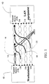
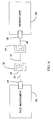
- FIG. 1 a diagrammatic representation of a typical 1 Gbps Ethernet Link between a workstation and LAN equipment
- the 1 Gbps Ethernet link between a workstation 10 and LAN equipment 12 uses 4 wire-pairs 14, 16, 18 and 20, with bi-directional transmission on each wire pair (transmit and receive).
- One of the signal transmission modes of 1 Gbps Ethernet on twisted pair cabling involves signals applied to one end of the link at the same time and traveling in parallel to the other end of the link.
- One major source of noise in this transmission mode results from coupling of one wire pair to another wire pair, as illustrated in FIG. 1.
- the impact of crosstalk on the wire pair 14 is shown at the top of FIG. 1 for a transmission from workstation 10 to LAN equipment 12.
- this signal disturbs the desired signal, which is the attenuated signal from the workstation end.
- the signal-to-noise ratio from this contribution is therefore the (linear) ratio of crosstalk amplitude and amplitude of the attenuated signal.
- the crosstalk signal in this case is called "Far End Crosstalk" (FEXT). If both the FEXT and attenuation are expressed in dB, the signal-to-noise ratio expressed in dB is obtained by calculating the difference between the FEXT and attenuation. This ratio is called Equal Level Far End Crosstalk ("ELFEXT").
- All wire pairs are noise sources for FEXT, and therefore add up. Since the signals on the wire pairs are generally uncorrelated, most often the combined effects of crosstalk from all wire pairs is summarized by taking the square root of the sum of the power of all crosstalk components (Power Sum FEXT, or Power Sum ELFEXT) to obtain an estimate for the total noise and signal-to-noise ratio at a receive input.
- Power Sum FEXT or Power Sum ELFEXT
- NEXT Near End Crosstalk
- Return Loss Other sources of noise in the 1 Gbps LAN system include Near End Crosstalk (NEXT) and Return Loss.
- NEXT performance is critical since signals arriving from the remote end of the link are disturbed by the output signals applied to the near end of the link. The bi-directional nature of signal on each wire pair results in reflected signals finding their way in the local receiver. Therefore, means are also designed in the 1 Gbps Ethernet system to compensate for this effect (“echo cancellation").
- the 1 Gbps Ethernet system includes means for "learning" crosstalk performance and providing compensation for some of the disturbing effects.
- NEXT, ELFEXT and return loss are important link parameters and therefore must be measured accurately.
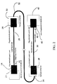
- a local equipment jack 22 receives a patch cord plug 24 therein.
- the local equipment may comprise a workstation, for example, or in the case of a testing situation, may be a test instrument for measuring and testing network performance.
- Patch cord plug 24 defines one end of patch cord 26, the other end thereof suitably comprising another patch cord plug 28.
- Plug 28 connects to link jack 30, which may comprise a wall jack in a typical installation.
- Link jack 30 defines the connection to link cable 32 which extends to jack 34 of the link. There may be several connectors in link cable segment 32.
- a remote patch cord 36 includes plugs 38 and 40 and connects between jack 34 and the jack 42 at the remote equipment.
- the formal definition of the link excludes the connection to the equipment at the local and remote ends, and therefore is defined as being between point 44, which is just to the patch cord side of local patch cord plug 24, and point 46, which is just to the patch cord side of remote plug 40.
- the performance of a LAN system is measured at the link side of a mating connector, and therefore the performance measurement of the link should not include the impact from that connection.
- Telecommunications Industry Association standard TSB-67 the standard cabling test configurations ("basic link” and "channel") specifically exclude this connection from the definition of the link.
- the international ISO/IEC 11801 cabling standard defines the channel configuration in the same manner.
- the user patch cord (e.g., cord 26 or cord 36) is employed during the measurements. Since the standard plug on a user patch cord for a generic cabling system as defined in TIA/EIA-568-A or ISO/IEC 11801 and 1 Gbps Ethernet system is a modular 8-pin RJ-45 connector, the mating jack on the instrument has to be a modular 8-pin RJ-45 type. Unfortunately, the crosstalk performance of a modular 8-pin connector is relatively poor and has a material influence on the measured performance of a link with those connectors included in the result. The FEXT resulting from the connection to the measurement instrument system at the local and remote end must be compensated for in order to report accurate measurement values. The computed ELFEXT is subject to the same compensation.
- a network technician may use a special patch cord, with the type of connector employed being one having low crosstalk characteristics.
- the transmission performance of the link using the special test cords is measured.
- the test configuration is not the actual configuration which ultimately carries the data during times other than in the test condition, since the user patch cord is removed during the test. Therefore, the measurements may not accurately represent the characteristics of the system once the special patch cord has been removed. Consequently, a method to accurately measure the channel configuration in addition to the basic link and permanent link test configuration is very desirable.
- the effects of crosstalk resulting from the connections local to and at the far end from a test instrument are subtracted from measurement results, providing FEXT and computed ELFEXT results that accurately describe those transmission parameters for the link.
- the system comprises a network test instrument having microprocessor controlled operations, for example.
- the system is configured to take various measurements and use those measurements to accurately determine all transmission parameters and in particular far end crosstalk.
- the crosstalk which results from capacitive and inductive imbalance, causes a crosstalk current in the disturbed wire pair with a fixed (90° or 270°) phase angle at the location where the crosstalk occurs.
- This is clear from circuit models of crosstalk in twisted pair wiring (Transmission Systems for Communication, Fourth Edition, February 1970, Members of Technical Staff Bell Laboratories: Chapter 11, Crosstalk, Section 11.3 Coupling Crosstalk).
- the distance to the point of measurement causes phase angle changes, which are proportional to the frequency of the test signal.
- the FEXT coupling is mainly determined by the properties of the jack and is relatively independent of the properties of the plug that mates with it.
- Test methods for jacks defined in the TIA/EIA-568A and ISO/IEC 11801 standards define the properties of plugs to be used to verify NEXT performance.
- a test using plugs with properties over a wider range than specified for NEXT performance results in relatively constant FEXT measurements between cable pairs.
- the 3,6 and 4,5 pair combinations are generally considered worst case. It was found that the variation of mated FEXT was only 2 dB for this pair combination.
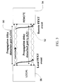
- FIG. 3 a diagram showing impact from FEXT in local and remote connections for a disturbing pair and a disturbed pair of a link
- FEXT/ELFEXT from pair 3,6 (disturber pair 50) to pair 4,5 (disturbed pair 52).
- the FEXT is measured ( FEXT 3,6-4,5 ) as is the attenuation of the 4,5 pair ( att 4,5 ).
- the ELFEXT for the 3,6-4,5 pair combination is then given by equation 1.
- ELFEXT 3,6-4,5 FEXT 3,6-4,5 att 4,5
- the FEXT as measured on the 4,5 pair at the remote end contains two additional, undesirable contributions, the FEXT from the local connector, FEXT loc , which is attenuated in the disturbed pair 4,5 in the amount of att 4,5 , and the FEXT from the remote connector, FEXT rem , which is attenuated in the disturber pair 3,6 before it arrives at the remote connector in the amount of att 3,6 .
- the total FEXT measured on the 4,5 pair at the remote end is given by equation 2.
- FEXT 3,6-4,5, total FEXT 3,6-4,5, link + att 4,5 * FEXT loc + att 3,6 * FEXT rem
- ELFEXT 3,6-4,5, total ELFEXT 3,6-4,5, link + FEXT loc + att 3,6 att 4,5 * FEXT rem
- ELFEXT 3,6-4,5 link ELFEXT 3,6-4,5, total - FEXT loc - att 3,6 att 4,5 * FEXT rem
- Each of these quantities is a vector type quantity, having relevant amplitude and phase information.
- the method of determining the ELFEXT of a link configuration as defined in TIA TSB-67 from the totally measured ELFEXT and previously measured connector FEXT can be implemented by measuring both amplitude and phase or real and imaginary parts of all quantities in equation (4).
- Equation (2a) can be re-written in terms of amplitude and phase to clarify the method of implementation as in equation (5).
- phase of the totally measured FEXT signal at the remote end, relative to the stimulus signal is unknown because the coupling may occur throughout the length of the link and therefore the total electrical distance traveled may depend on where the coupling occurs. In many practical situations some assumptions may be used, which considerably simplify the computations.
- Equation (5) can be re-written as:
- equation (7) Since the test limit for the absolute value of ELFEXT is specified, equation (7) becomes:
- Real world cables have different twist rates for multi-pair twisted pair cabling in order to average out crosstalk and therefore to reduce the observed crosstalk. This is the reason that the attenuation of different wire pairs can be different. However, most often, differences are small, and attenuation of different wire pairs may often be considered equal.
- equation (8) simplifies to:
- the main impact from twist rate differences is that the propagation delay in wire pairs differs. Accordingly, substantial differences in phase delay may occur.
- the allowed delay skew difference in propagation delay
- Compliant links per TIA/EIA-568-A and ISO/IEC 11801 have a maximum length of 100 m.
- the highest frequency for category 5 cabling is 100 Mhz. For higher performance cabling standards, significantly higher highest frequencies are being considered.
- the simplification used to compute the ELFEXT loss of the defined link is determined by the additional measurement error that may result from the simplification. Practically, it is a fraction of the total measurement error. Typically, allowable error will be any order of a fraction of decibel, and any decision to use this simplification is suitably based on keeping any error amount in the fractional decibel range.
- equation (10) simplifies further to: Note that all quantities in equation (11) are magnitude only quantities.
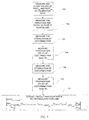
- the frequency response of the assembly will show nulls as shown in FIG. 4, a graph showing calculated total FEXT from equal local and remote connector FEXT contributions. If there were no difference in propagation delay in disturber and disturbed pair, these nulls would not exist.
- the remote connector term in equation (4) contains a factor equal to the ratio of attenuation in both wire pairs. When assuming that the ratio is exactly equal to 1, only a minor change occurs in the predicted FEXT/ELFEXT.
- simplifications may be applied to obtain the best possible accuracy of ELFEXT results with a minimum measurement time.
- Such simplifications are suitably selected in accordance with a software control program operating a test instrument embodying the invention.
- the above noted conditions regarding link size, frequency/wavelength, crosstalk, etc. are employed to select which particular simplification (if any) is employed to determine the far end crosstalk.
- step 100 the process is to measure and store as calibration data the values of FEXT loc and FEXT rem (step 100). Then, in step 102, the amplitude and phase of the FEXT is taken, measured at the remote end. Practically, the phase of the total FEXT is measured relative to the phase of the attenuated signal at the remote end of the disturbing wire pair.
- step 104 the attenuation of the disturbed pair is measured att 4,5 , followed by measuring the propagation delay of the disturbed pair t prop,45 (step 106). The attenuation of the disturbing pair is measured next (step 108).
- Equation (8) the propagation delay of the disturbing pair is measured t prop,36 (step 110), whereupon the measured values are employed in equation (8).
- equation 9, 10 or 11 step 112 to obtain the ELFEXT for the defined link.
- pair 3,6 is considered to be the disturber pair
- pair 4,5 is the disturbed pair.
- the actual pairs employed in a given measurement will depend on the configuration being measured. Reference herein to pair 3,6 and 4,5 may therefore be substituted to mean reference to any disturber and disturbed pair, respectively. In test and measurement of an actual link, all pair combinations would be tested and measurements made for each pair in relation to all other pairs, to provide an overall view of the ELFEXT characteristics of the link.
- a test instrument 56 receives patch cord plug 24 (see FIG. 2) therein (a jack corresponding to jack 22 of FIG. 2 is provided in instrument 56).
- Local patch cord 26 connects the instrument to the link, via plug 28 and jack 30.
- Link cable 32 which will typically have plural other jacks connected thereto, extends to the last jack 34 of the link.
- a remote patch cord 36 includes plugs 38 and 40 and connects between jack 34 and the jack 42 at the remote unit 58. Either of the remote unit or the test instrument provides stimulus at one end of the link and the other records the measurements at the other end.
- the particular stimulus and measurement used to measure crosstalk are know to those of skill in the art, and are not detailed herein.
Landscapes
- Engineering & Computer Science (AREA)
- Computer Networks & Wireless Communication (AREA)
- Signal Processing (AREA)
- Physics & Mathematics (AREA)
- General Physics & Mathematics (AREA)
- Cable Transmission Systems, Equalization Of Radio And Reduction Of Echo (AREA)
- Testing Of Short-Circuits, Discontinuities, Leakage, Or Incorrect Line Connections (AREA)
- Measurement Of Resistance Or Impedance (AREA)
- Monitoring And Testing Of Transmission In General (AREA)
Priority Applications (1)
| Application Number | Priority Date | Filing Date | Title |
|---|---|---|---|
| EP06075857A EP1681777B1 (fr) | 1998-09-11 | 1999-09-06 | Procédé et appareil de mesure de télédiaphonie |
Applications Claiming Priority (2)
| Application Number | Priority Date | Filing Date | Title |
|---|---|---|---|
| US152153 | 1998-09-11 | ||
| US09/152,153 US6285653B1 (en) | 1998-09-11 | 1998-09-11 | Method and apparatus to measure far end crosstalk for the determination of equal level far end crosstalk |
Related Child Applications (1)
| Application Number | Title | Priority Date | Filing Date |
|---|---|---|---|
| EP06075857A Division EP1681777B1 (fr) | 1998-09-11 | 1999-09-06 | Procédé et appareil de mesure de télédiaphonie |
Publications (3)
| Publication Number | Publication Date |
|---|---|
| EP0985933A2 true EP0985933A2 (fr) | 2000-03-15 |
| EP0985933A3 EP0985933A3 (fr) | 2003-07-30 |
| EP0985933B1 EP0985933B1 (fr) | 2006-06-07 |
Family
ID=22541712
Family Applications (2)
| Application Number | Title | Priority Date | Filing Date |
|---|---|---|---|
| EP99307067A Expired - Lifetime EP0985933B1 (fr) | 1998-09-11 | 1999-09-06 | Méthode et appareil pour la mesure de la télédiaphonie pour déterminer le rapport entre la télédiaphonie et l'atténuation |
| EP06075857A Expired - Lifetime EP1681777B1 (fr) | 1998-09-11 | 1999-09-06 | Procédé et appareil de mesure de télédiaphonie |
Family Applications After (1)
| Application Number | Title | Priority Date | Filing Date |
|---|---|---|---|
| EP06075857A Expired - Lifetime EP1681777B1 (fr) | 1998-09-11 | 1999-09-06 | Procédé et appareil de mesure de télédiaphonie |
Country Status (7)
| Country | Link |
|---|---|
| US (1) | US6285653B1 (fr) |
| EP (2) | EP0985933B1 (fr) |
| JP (1) | JP3484377B2 (fr) |
| KR (1) | KR100676519B1 (fr) |
| CN (1) | CN100409591C (fr) |
| DE (2) | DE69931713T2 (fr) |
| TW (1) | TW444124B (fr) |
Cited By (6)
| Publication number | Priority date | Publication date | Assignee | Title |
|---|---|---|---|---|
| EP1246398A2 (fr) | 2001-03-02 | 2002-10-02 | Broadcom Corporation | Méthode et dispositif pour exécuter le test de diagnostic en utilisant un émetteur récepteur assistant |
| EP1300964A1 (fr) * | 2001-10-03 | 2003-04-09 | Alcatel | Système e méthode pour la mesure de la diaphonie dans un resau XDSL |
| EP1429493A2 (fr) | 2002-12-12 | 2004-06-16 | Ideal Industries Inc. | Appareil de test tenu dans la main et méthode de test pour le câblage local de réseau |
| GB2413640A (en) * | 2004-04-30 | 2005-11-02 | Fluke Corp | Cable Testing Using Main And Remote Units |
| WO2005104782A2 (fr) | 2004-04-27 | 2005-11-10 | Fluke Corporation | Annulation de telediaphonie d'une interconnexion rj45 accouplee |
| US7342400B2 (en) | 2004-05-03 | 2008-03-11 | Fluke Corporation | Method and apparatus for measuring employing main and remote units |
Families Citing this family (43)
| Publication number | Priority date | Publication date | Assignee | Title |
|---|---|---|---|---|
| JP3097677B2 (ja) * | 1998-10-08 | 2000-10-10 | 三菱電機株式会社 | 通信装置および通信方法 |
| US7085230B2 (en) * | 1998-12-24 | 2006-08-01 | Mci, Llc | Method and system for evaluating the quality of packet-switched voice signals |
| US7653002B2 (en) * | 1998-12-24 | 2010-01-26 | Verizon Business Global Llc | Real time monitoring of perceived quality of packet voice transmission |
| US6985559B2 (en) * | 1998-12-24 | 2006-01-10 | Mci, Inc. | Method and apparatus for estimating quality in a telephonic voice connection |
| US7099282B1 (en) * | 1998-12-24 | 2006-08-29 | Mci, Inc. | Determining the effects of new types of impairments on perceived quality of a voice service |
| SE514948C2 (sv) * | 1999-03-29 | 2001-05-21 | Ericsson Telefon Ab L M | Förfarande och anordning för att reducera överhörning |
| US6895081B1 (en) * | 1999-04-20 | 2005-05-17 | Teradyne, Inc. | Predicting performance of telephone lines for data services |
| GB2355361B (en) * | 1999-06-23 | 2004-04-14 | Teradyne Inc | Qualifying telephone lines for data transmission |
| US6487276B1 (en) * | 1999-09-30 | 2002-11-26 | Teradyne, Inc. | Detecting faults in subscriber telephone lines |
| US6704277B1 (en) * | 1999-12-29 | 2004-03-09 | Intel Corporation | Testing for digital signaling |
| GB0005227D0 (en) * | 2000-03-03 | 2000-04-26 | Teradyne Inc | Technique for estimatio of insertion loss |
| US7016822B2 (en) * | 2000-06-30 | 2006-03-21 | Qwest Communications International, Inc. | Method and system for modeling near end crosstalk in a binder group |
| GB2365253B (en) * | 2000-07-19 | 2004-06-16 | Teradyne Inc | Method of performing insertion loss estimation |
| WO2002058369A2 (fr) * | 2000-10-19 | 2002-07-25 | Teradyne, Inc. | Procede et systeme pour analyser l'impact d'un branchement en derivation |
| US6553061B1 (en) | 2001-02-08 | 2003-04-22 | Worldcom, Inc. | Method and apparatus for detecting a waveform |
| DE60219622T2 (de) * | 2001-05-30 | 2007-12-27 | Worldcom, Inc., Clinton | Bestimmung der effekte neuer arten von beeinträchtigungen auf die wahrgenommene qualität eines sprachdienstes |
| US6961373B2 (en) * | 2002-07-01 | 2005-11-01 | Solarflare Communications, Inc. | Method and apparatus for channel equalization |
| US7133425B2 (en) * | 2002-07-10 | 2006-11-07 | Solarflare Communications, Inc. | Communication system |
| US7809021B2 (en) * | 2002-07-10 | 2010-10-05 | Solarflare Communications, Inc. | Communication system and encoding method having low overhead |
| US7164764B2 (en) * | 2002-11-07 | 2007-01-16 | Solarflare Communications, Inc. | Method and apparatus for precode crosstalk mitigation |
| CN100520418C (zh) * | 2002-12-12 | 2009-07-29 | 理想工业公司 | 局域网电缆线路测试系统及局域网测试器的接插线长度测量 |
| WO2004055527A1 (fr) * | 2002-12-12 | 2004-07-01 | Ideal Industries, Inc. | Mesure de la longueur d'un cordon de brassage pour testeurs de reseau local |
| US8363535B2 (en) * | 2003-04-28 | 2013-01-29 | Marvell International Ltd. | Frequency domain echo and next cancellation |
| US20040213354A1 (en) * | 2003-04-28 | 2004-10-28 | Jones William W. | Mixed domain cancellation |
| US7002897B2 (en) * | 2003-04-28 | 2006-02-21 | Solarflare Communications, Inc. | Multiple channel interference cancellation |
| JP4881736B2 (ja) | 2003-05-16 | 2012-02-22 | マーベル インターナショナル リミテッド | イコライゼーションおよびクロストーク緩和の方法および器具 |
| JP5006036B2 (ja) | 2003-07-11 | 2012-08-22 | パンドウィット・コーポレーション | 強化パッチコードによるエイリアン・クロストーク抑制 |
| US8140980B2 (en) | 2003-08-05 | 2012-03-20 | Verizon Business Global Llc | Method and system for providing conferencing services |
| US7386039B2 (en) * | 2003-09-26 | 2008-06-10 | Tollgrade Communications, Inc. | Method and apparatus for identifying faults in a broadband network |
| US7593315B2 (en) * | 2004-02-09 | 2009-09-22 | Cisco Technology, Inc. | Cable diagnostics for 10GBASE-T transceivers |
| CN100336311C (zh) * | 2004-02-12 | 2007-09-05 | 中兴通讯股份有限公司 | 一种解决数字用户线路远端串扰的方法 |
| CN1965498B (zh) * | 2004-05-18 | 2013-03-06 | 适应性频谱和信号校正股份有限公司 | 估计多线路、矢量化dsl系统的运行特性的方法和设备 |
| US7081763B1 (en) * | 2005-08-03 | 2006-07-25 | Agilent Technologies, Inc. | Test system and method for field measurement of alien cross-talk |
| EP1760904B1 (fr) * | 2005-08-29 | 2011-10-19 | Alcatel Lucent | Procédé et appareil à mesurer la diaphonie |
| US8761387B2 (en) | 2006-05-04 | 2014-06-24 | Mindspeed Technologies, Inc. | Analog transmit crosstalk canceller |
| US7720068B2 (en) | 2006-08-23 | 2010-05-18 | Solarflare Communications, Inc. | Method and system for a multi-rate gigabit media independent interface |
| US7808407B2 (en) * | 2007-06-15 | 2010-10-05 | Solarflare Communications, Inc. | Sub-channel distortion mitigation in parallel digital systems |
| US7948862B2 (en) | 2007-09-26 | 2011-05-24 | Solarflare Communications, Inc. | Crosstalk cancellation using sliding filters |
| US8984304B2 (en) * | 2007-11-12 | 2015-03-17 | Marvell International Ltd. | Active idle communication system |
| US8320555B2 (en) * | 2008-09-12 | 2012-11-27 | Centurylink Intellectual Property Llc | Method and apparatus for determining a change in network-generated crosstalk levels caused by a multi-line phone |
| US8357013B2 (en) * | 2009-01-22 | 2013-01-22 | Hirose Electric Co., Ltd. | Reducing far-end crosstalk in electrical connectors |
| CN105956309B (zh) * | 2016-05-13 | 2019-05-14 | 南京航空航天大学 | 一种消除传输线远端稳态串扰的“编码器”设计方法 |
| CN112865836B (zh) * | 2020-12-22 | 2023-03-31 | 中天通信技术有限公司 | 电缆测量方法以及室内分布式天线系统 |
Citations (1)
| Publication number | Priority date | Publication date | Assignee | Title |
|---|---|---|---|---|
| US5731706A (en) * | 1997-02-18 | 1998-03-24 | Koeman; Henriecus | Method for efficient calculation of power sum cross-talk loss |
Family Cites Families (7)
| Publication number | Priority date | Publication date | Assignee | Title |
|---|---|---|---|---|
| US557029A (en) * | 1896-03-24 | Drying apparatus for cans | ||
| US5502391A (en) * | 1992-09-11 | 1996-03-26 | Microtest, Inc. | Apparatus for measuring the crosstalk in a cable |
| US5570029A (en) * | 1994-03-30 | 1996-10-29 | Fluke Corporation | Cable crosstalk measurement system |
| US5548222A (en) * | 1994-09-29 | 1996-08-20 | Forte Networks | Method and apparatus for measuring attenuation and crosstalk in data and communication channels |
| US5532603A (en) * | 1995-01-27 | 1996-07-02 | Fluke Corporation | Cross-talk measurement apparatus with near-end compensation |
| EP0789462B1 (fr) * | 1996-02-12 | 2004-09-29 | Fluke Corporation | Procédé et appareil pour traiter des données de diaphonie dans le domaine temporel |
| US5821760A (en) * | 1996-07-31 | 1998-10-13 | Fluke Corporation | Method and apparatus for measuring near-end cross-talk in patch cords |
-
1998
- 1998-09-11 US US09/152,153 patent/US6285653B1/en not_active Expired - Lifetime
-
1999
- 1999-08-27 TW TW088114707A patent/TW444124B/zh not_active IP Right Cessation
- 1999-09-06 EP EP99307067A patent/EP0985933B1/fr not_active Expired - Lifetime
- 1999-09-06 DE DE69931713T patent/DE69931713T2/de not_active Expired - Lifetime
- 1999-09-06 DE DE69940749T patent/DE69940749D1/de not_active Expired - Lifetime
- 1999-09-06 EP EP06075857A patent/EP1681777B1/fr not_active Expired - Lifetime
- 1999-09-09 JP JP25507999A patent/JP3484377B2/ja not_active Expired - Fee Related
- 1999-09-10 KR KR1019990038520A patent/KR100676519B1/ko not_active IP Right Cessation
- 1999-09-13 CN CNB991193741A patent/CN100409591C/zh not_active Expired - Fee Related
Patent Citations (1)
| Publication number | Priority date | Publication date | Assignee | Title |
|---|---|---|---|---|
| US5731706A (en) * | 1997-02-18 | 1998-03-24 | Koeman; Henriecus | Method for efficient calculation of power sum cross-talk loss |
Non-Patent Citations (1)
| Title |
|---|
| KOEMAN H: "Modeling and measuring ELFEXT link performance" , BROADBAND ACCESS AND NETWORK MANAGEMENT NOC '98, PROCEEDINGS OF NOC '98 EUROPEAN CONFERENCE ON NETWORKS AND OPTICAL COMMUNICATIONS, MANCHESTER, UK, 23-25 JUNE 1998 , 1998, AMSTERDAM, NETHERLANDS, IOS PRESS, NETHERLANDS, PAGE(S) 316 - 321 XP009011860 ISBN: 90-5199-400-1 * page 317, chapter 2 * * pages 318-320, chapter 4 * * figures 1,3 * * |
Cited By (13)
| Publication number | Priority date | Publication date | Assignee | Title |
|---|---|---|---|---|
| EP1246398A3 (fr) * | 2001-03-02 | 2002-10-23 | Broadcom Corporation | Méthode et dispositif pour exécuter le test de diagnostic en utilisant un émetteur récepteur assistant |
| US7701867B2 (en) | 2001-03-02 | 2010-04-20 | Broadcom Corporation | Method and apparatus for performing diagnostic tests using an assisting transceiver |
| EP1246398A2 (fr) | 2001-03-02 | 2002-10-02 | Broadcom Corporation | Méthode et dispositif pour exécuter le test de diagnostic en utilisant un émetteur récepteur assistant |
| US7068611B2 (en) | 2001-03-02 | 2006-06-27 | Broadcom Corporation | Method and apparatus for performing diagnostic tests using an assisting transceiver |
| US7664254B2 (en) | 2001-10-03 | 2010-02-16 | Alcatel | System and method for upstream power backoff for xDSL |
| EP1300964A1 (fr) * | 2001-10-03 | 2003-04-09 | Alcatel | Système e méthode pour la mesure de la diaphonie dans un resau XDSL |
| EP1429493A2 (fr) | 2002-12-12 | 2004-06-16 | Ideal Industries Inc. | Appareil de test tenu dans la main et méthode de test pour le câblage local de réseau |
| EP1429493A3 (fr) * | 2002-12-12 | 2011-08-03 | Ideal Industries Inc. | Appareil de test tenu dans la main et méthode de test pour le câblage local de réseau |
| WO2005104782A2 (fr) | 2004-04-27 | 2005-11-10 | Fluke Corporation | Annulation de telediaphonie d'une interconnexion rj45 accouplee |
| GB2413640B (en) * | 2004-04-30 | 2008-02-06 | Fluke Corp | Method and apparatus for measuring employing main and remote units |
| FR2869690A1 (fr) * | 2004-04-30 | 2005-11-04 | Fluke Corp | Procede et dispositif de mesure employant des unites principale et distante |
| GB2413640A (en) * | 2004-04-30 | 2005-11-02 | Fluke Corp | Cable Testing Using Main And Remote Units |
| US7342400B2 (en) | 2004-05-03 | 2008-03-11 | Fluke Corporation | Method and apparatus for measuring employing main and remote units |
Also Published As
| Publication number | Publication date |
|---|---|
| JP3484377B2 (ja) | 2004-01-06 |
| DE69931713D1 (de) | 2006-07-20 |
| EP0985933B1 (fr) | 2006-06-07 |
| EP1681777A1 (fr) | 2006-07-19 |
| CN1248826A (zh) | 2000-03-29 |
| KR20000023049A (ko) | 2000-04-25 |
| DE69940749D1 (de) | 2009-05-28 |
| CN100409591C (zh) | 2008-08-06 |
| KR100676519B1 (ko) | 2007-01-31 |
| DE69931713T2 (de) | 2007-05-16 |
| US6285653B1 (en) | 2001-09-04 |
| EP1681777B1 (fr) | 2009-04-15 |
| EP0985933A3 (fr) | 2003-07-30 |
| JP2000101489A (ja) | 2000-04-07 |
| TW444124B (en) | 2001-07-01 |
Similar Documents
| Publication | Publication Date | Title |
|---|---|---|
| US6285653B1 (en) | Method and apparatus to measure far end crosstalk for the determination of equal level far end crosstalk | |
| JP2745297B2 (ja) | クロストーク応答を測定するための計器 | |
| KR100205676B1 (ko) | 패치코드에서의 전단누화를 측정하는 방법 및 장치 | |
| US5128619A (en) | System and method of determining cable characteristics | |
| US8065100B2 (en) | Method and a system for cable or subscriber loop investigation performing loop topology identification | |
| EP0789462B1 (fr) | Procédé et appareil pour traiter des données de diaphonie dans le domaine temporel | |
| EP0859473B1 (fr) | Procédé de calculation efficace de la perte diaphonique à somme de puissance | |
| US8290122B2 (en) | Method and device for estimating properties of a telecommunication transmission line | |
| US7385932B2 (en) | Wideband frequency domain reflectometry to determine the nature and location of subscriber line faults | |
| EP3433937B1 (fr) | Procédé et système pour estimer la diaphonie entre des lignes de transmission électriques | |
| WO2002033941A1 (fr) | Procede et dispositif permettant de tester des lignes telephoniques et de donnees dans un systeme de telecommunications | |
| RU2406224C2 (ru) | Способ, устройство и программный продукт для оценки свойств линии передачи системы связи | |
| Koeman | Testing local area network cabling for high speed communications |
Legal Events
| Date | Code | Title | Description |
|---|---|---|---|
| PUAI | Public reference made under article 153(3) epc to a published international application that has entered the european phase |
Free format text: ORIGINAL CODE: 0009012 |
|
| AK | Designated contracting states |
Kind code of ref document: A2 Designated state(s): AT BE CH CY DE DK ES FI FR GB GR IE IT LI LU MC NL PT SE |
|
| AX | Request for extension of the european patent |
Free format text: AL;LT;LV;MK;RO;SI |
|
| PUAL | Search report despatched |
Free format text: ORIGINAL CODE: 0009013 |
|
| AK | Designated contracting states |
Designated state(s): AT BE CH CY DE DK ES FI FR GB GR IE IT LI LU MC NL PT SE |
|
| AX | Request for extension of the european patent |
Extension state: AL LT LV MK RO SI |
|
| 17P | Request for examination filed |
Effective date: 20040121 |
|
| AKX | Designation fees paid |
Designated state(s): DE FR GB |
|
| 17Q | First examination report despatched |
Effective date: 20050426 |
|
| GRAP | Despatch of communication of intention to grant a patent |
Free format text: ORIGINAL CODE: EPIDOSNIGR1 |
|
| GRAS | Grant fee paid |
Free format text: ORIGINAL CODE: EPIDOSNIGR3 |
|
| GRAA | (expected) grant |
Free format text: ORIGINAL CODE: 0009210 |
|
| AK | Designated contracting states |
Kind code of ref document: B1 Designated state(s): DE FR GB |
|
| REG | Reference to a national code |
Ref country code: GB Ref legal event code: FG4D |
|
| REF | Corresponds to: |
Ref document number: 69931713 Country of ref document: DE Date of ref document: 20060720 Kind code of ref document: P |
|
| ET | Fr: translation filed | ||
| PLBE | No opposition filed within time limit |
Free format text: ORIGINAL CODE: 0009261 |
|
| STAA | Information on the status of an ep patent application or granted ep patent |
Free format text: STATUS: NO OPPOSITION FILED WITHIN TIME LIMIT |
|
| 26N | No opposition filed |
Effective date: 20070308 |
|
| REG | Reference to a national code |
Ref country code: FR Ref legal event code: PLFP Year of fee payment: 18 |
|
| REG | Reference to a national code |
Ref country code: FR Ref legal event code: PLFP Year of fee payment: 19 |
|
| REG | Reference to a national code |
Ref country code: FR Ref legal event code: PLFP Year of fee payment: 20 |
|
| PGFP | Annual fee paid to national office [announced via postgrant information from national office to epo] |
Ref country code: FR Payment date: 20180925 Year of fee payment: 20 Ref country code: DE Payment date: 20180927 Year of fee payment: 20 |
|
| PGFP | Annual fee paid to national office [announced via postgrant information from national office to epo] |
Ref country code: GB Payment date: 20180927 Year of fee payment: 20 |
|
| REG | Reference to a national code |
Ref country code: DE Ref legal event code: R071 Ref document number: 69931713 Country of ref document: DE |
|
| REG | Reference to a national code |
Ref country code: GB Ref legal event code: PE20 Expiry date: 20190905 |
|
| PG25 | Lapsed in a contracting state [announced via postgrant information from national office to epo] |
Ref country code: GB Free format text: LAPSE BECAUSE OF EXPIRATION OF PROTECTION Effective date: 20190905 |