EP0985883B1 - Heating means - Google Patents
Heating means Download PDFInfo
- Publication number
- EP0985883B1 EP0985883B1 EP99116096A EP99116096A EP0985883B1 EP 0985883 B1 EP0985883 B1 EP 0985883B1 EP 99116096 A EP99116096 A EP 99116096A EP 99116096 A EP99116096 A EP 99116096A EP 0985883 B1 EP0985883 B1 EP 0985883B1
- Authority
- EP
- European Patent Office
- Prior art keywords
- combustion chamber
- fuel
- heating
- conveyor
- heating means
- Prior art date
- Legal status (The legal status is an assumption and is not a legal conclusion. Google has not performed a legal analysis and makes no representation as to the accuracy of the status listed.)
- Expired - Lifetime
Links
- 238000010438 heat treatment Methods 0.000 title claims abstract description 30
- 238000002485 combustion reaction Methods 0.000 claims abstract description 85
- 239000000446 fuel Substances 0.000 claims abstract description 32
- 239000008188 pellet Substances 0.000 claims description 36
- 239000002023 wood Substances 0.000 claims description 18
- 238000001816 cooling Methods 0.000 claims description 4
- 235000007466 Corylus avellana Nutrition 0.000 claims description 2
- 240000009226 Corylus americana Species 0.000 claims 1
- 235000001543 Corylus americana Nutrition 0.000 claims 1
- 239000000463 material Substances 0.000 abstract description 14
- 239000000779 smoke Substances 0.000 abstract description 8
- CURLTUGMZLYLDI-UHFFFAOYSA-N Carbon dioxide Chemical compound O=C=O CURLTUGMZLYLDI-UHFFFAOYSA-N 0.000 description 10
- 229910002092 carbon dioxide Inorganic materials 0.000 description 5
- 239000001569 carbon dioxide Substances 0.000 description 5
- 239000003638 chemical reducing agent Substances 0.000 description 4
- 239000007787 solid Substances 0.000 description 4
- 238000004519 manufacturing process Methods 0.000 description 3
- 238000013021 overheating Methods 0.000 description 3
- UGFAIRIUMAVXCW-UHFFFAOYSA-N Carbon monoxide Chemical compound [O+]#[C-] UGFAIRIUMAVXCW-UHFFFAOYSA-N 0.000 description 2
- 229910002091 carbon monoxide Inorganic materials 0.000 description 2
- 238000004140 cleaning Methods 0.000 description 2
- 230000007547 defect Effects 0.000 description 2
- 230000000694 effects Effects 0.000 description 2
- 230000007613 environmental effect Effects 0.000 description 2
- 230000001902 propagating effect Effects 0.000 description 2
- 239000004449 solid propellant Substances 0.000 description 2
- 241000723382 Corylus Species 0.000 description 1
- 235000002918 Fraxinus excelsior Nutrition 0.000 description 1
- 239000000654 additive Substances 0.000 description 1
- 239000002956 ash Substances 0.000 description 1
- 230000015572 biosynthetic process Effects 0.000 description 1
- 239000002828 fuel tank Substances 0.000 description 1
- 239000003517 fume Substances 0.000 description 1
- 239000011521 glass Substances 0.000 description 1
- 230000005484 gravity Effects 0.000 description 1
- 239000011796 hollow space material Substances 0.000 description 1
- 238000003780 insertion Methods 0.000 description 1
- 230000037431 insertion Effects 0.000 description 1
- 230000000149 penetrating effect Effects 0.000 description 1
- 230000035515 penetration Effects 0.000 description 1
- 230000000630 rising effect Effects 0.000 description 1
- 238000006467 substitution reaction Methods 0.000 description 1
- 238000003786 synthesis reaction Methods 0.000 description 1
- 230000000007 visual effect Effects 0.000 description 1
Images


Classifications
-
- F—MECHANICAL ENGINEERING; LIGHTING; HEATING; WEAPONS; BLASTING
- F24—HEATING; RANGES; VENTILATING
- F24B—DOMESTIC STOVES OR RANGES FOR SOLID FUELS; IMPLEMENTS FOR USE IN CONNECTION WITH STOVES OR RANGES
- F24B1/00—Stoves or ranges
- F24B1/02—Closed stoves
- F24B1/024—Closed stoves for pulverulent fuels
-
- F—MECHANICAL ENGINEERING; LIGHTING; HEATING; WEAPONS; BLASTING
- F24—HEATING; RANGES; VENTILATING
- F24B—DOMESTIC STOVES OR RANGES FOR SOLID FUELS; IMPLEMENTS FOR USE IN CONNECTION WITH STOVES OR RANGES
- F24B13/00—Details solely applicable to stoves or ranges burning solid fuels
- F24B13/04—Arrangements for feeding solid fuel, e.g. hoppers
-
- Y—GENERAL TAGGING OF NEW TECHNOLOGICAL DEVELOPMENTS; GENERAL TAGGING OF CROSS-SECTIONAL TECHNOLOGIES SPANNING OVER SEVERAL SECTIONS OF THE IPC; TECHNICAL SUBJECTS COVERED BY FORMER USPC CROSS-REFERENCE ART COLLECTIONS [XRACs] AND DIGESTS
- Y02—TECHNOLOGIES OR APPLICATIONS FOR MITIGATION OR ADAPTATION AGAINST CLIMATE CHANGE
- Y02A—TECHNOLOGIES FOR ADAPTATION TO CLIMATE CHANGE
- Y02A40/00—Adaptation technologies in agriculture, forestry, livestock or agroalimentary production
- Y02A40/90—Adaptation technologies in agriculture, forestry, livestock or agroalimentary production in food processing or handling, e.g. food conservation
- Y02A40/924—Adaptation technologies in agriculture, forestry, livestock or agroalimentary production in food processing or handling, e.g. food conservation using renewable energies
- Y02A40/928—Cooking stoves using biomass
Definitions
- the invention relates to heating means in order to heat residential rooms.
- the prior art includes wood-burning stoves provided with a combustion chamber which is loaded with firewood through an opening, that can be closed by a shutter, obtained on a side wall delimiting a combustion chamber.
- the smokes produced by the wood combustion are ejected through a smoke pipe communicating the combustion chamber to the exterior.
- a defect of such devices results from the used fuel type, whose combustion causes a relative high production of carbon monoxide which is responsible of environmental problems such as the rising of the average temperature of our planet due to the so-called greenhouse effect.
- a further defect is found in the high amount of solid residual combustion products which force the user to accomplish frequent and tiring cleaning operations.
- Heating devices are furthermore known which use as fuel the so-called "pellets" of wood. These pellets are obtained from residual products of the wood working (sawdust or chips) which are subjected to a high pressure in order to obtain compact products having a substantially cylindrical shape. The pellets are obtained without the use of polluting additives; they are characterized by a very low humidity percentage and therefore they burn easily. The combustion of such products furthermore produces a rather low amount of solid residual products; also the production of carbon monoxide results equally low. Furthermore, the synthesis of carbon dioxide (CO2) during the combustion appears compatible with the environmental requirements.
- Devices which use the pellets as fuel comprise a combustion chamber delimited by a wall on which an opening is obtained that can be closed by a shutter. At the interior of the combustion chamber is accommodated a brazier designed to receive the pellets in order to contain them while burning.
- a suction and smokes unloading chamber provided with a fan suitable to intake the smokes themselves and to produce a vacuum pressure needed to create an air flow inside the combustion chamber essential in order to cause that the pellets can burn. Instead a smoke pipe does not appear as necessary as in the usual wood-burning stoves due to the low production of CO2 generated by the combustion of the pellets.
- a further fan placed in a lower region of the device, draws air from the external environment and conveys it along a suitable path so as air is heated and again admitted into the external environment.
- a fuel tank, near the combustion chamber is suitable to contain a high amount of pellets so as to assure to the device a considerable working duration.
- the fuel loading into the brazier results through a screw conveyor (driven by a motor-reducer) which draws the pellets from a bottom region of the tank in order to convey them inside the combustion chamber in a region above the brazier. From this last region, a slide ramp of suitable length drives the fuel fall into the brazier.
- the apparatus can be furthermore equipped with an electronic board suitable to accomplish different operations such as the ignition, the putting out and the selection of a stated temperature.
- the keeping of the desired temperature and of a suitable pressure inside the combustion chamber is accomplished by devices as pressure and thermo-swithces that interact with the fans and the motor-reducer.
- DE 3226877 discloses a boiler, suitable for alternative or joint combustion of wood chippings and/or sawdust and pieces of wood, provided with a combustion chamber to which a conveying device, a combustion-air supply device, an exhaust fume conduit and a hot-air exchange device are connected.
- the combustion chamber has a combustion grille that occupies from 40% to 80% of the transverse section of the combustion chamber, the conveying device leads into a loading hopper that occupies the section surface of the combustion chamber kept free by the grille.
- the above-mentioned devices can not properly work while accomplishing the combustion of other types of fuel such as the natural wood; in effect the excessive amount of CO2 produced could not be delivered without a smoke pipe.
- Apparatus for the heating of rooms are furthermore known, the so-called fire-places, constituted by a hearth open toward the room to be heated, wherein the fuel to be burnt is placed, generally pieces of wood, and a smoke pipe for the unloading of the smokes produced by the combustion.
- These devices have a very low efficiency, because a large amount of the heat produced by the combustion is wasted through the smoke pipe. Furthermore they do not allow to use fuel in small pieces, such as the wood pellets.
- a heating means according to the preamble of claim 1 is known from DE-U-9218953.
- An object of the present invention is to improve the known means for the heating of residential rooms.
- a further object is to make more versatile the known means for the heating of residential rooms.
- Another object of the present invention is to make more safe the above-mentioned means for the heating of residential rooms.
- Still another object of the present invention is to improve the efficiency of the fire-places.
- the first fuel materials can be pieces of natural wood, while the second fuel materials can be pellets of wood, solid fuels of small size, or granular, for example fuel materials shattered as olive-stones brushed and shattered, walnut-shells, or hazel-nuts, or other else.
- combustion chamber and the container means constitute two distinct units interconnected by the conveyor means.
- the conveyor means advantageously includes in a first section screw conveyor means and possibly in a second section a slide ramp suitable to drive the fall of the pellets into a brazier of the combustion chamber.
- the means for heating of rooms is constituted by a single unit and the combustion chamber and the container means are separated by a dividing wall.
- the container means may be provided suitable to contain solid, granular fuel materials and conveyor means of said solid, granular fuel materials which is suitable to convey said granular, solid fuel materials between said container means and a combustion chamber.
- the set of the heating means and the container means presents such shape and dimensions that it can be inserted into the hearth of a fire-place.
- the means for the heating of rooms is provided including a combustion chamber provided with an inlet arranged to introduce first fuel materials in said combustion chamber, an outlet through which combustion smokes can leave said combustion chamber, and includes furthermore cooling means suitable to cool said further fuel means in said conveyor means.
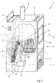
- a domestic stove 1 includes a combustion chamber 2 suitable to be loaded with wood 3 that can be introduced into the combustion chamber 2 through an opening 4.
- the air heated by the combustion of the wood 3 propagates to the environment to be heated through outlet slot 5, obtained at the top of the combustion chamber 2, besides by irradiation.
- the smokes produced by the combustion, containing a high amount of CO2 are ejected through a smoke pipe 6 which connects the combustion chamber 2 to an environment external to the room to be heated.
- Container means 7 suitable to contain pellets 8 shows a loading opening 9 obtained at the top of the container means 7 and suitable to allow the loading of pellets 8 inside the container means 7.
- the pellets 8 are subject to be conveyed from the container means 7 to the combustion chamber 2 through an Archimedean screw conveyor 10 driven by a motor-reducer 11 ( Figure 2).
- the Archimedean screw conveyor 10 is suitable to draw the pellets 8 from a bottom region of the container means 7 through a mouth 10a ( Figure 3) provided in a bottom region of a covering 10b of the Archimedean screw conveyor 10.
- the pellets drawn through the mouth 10a are transferred to the top of a gravity duct, or slide ramp, 12 which is suitable to drive the fall of the pellets 8 toward a brazier 13 placed at the inner side of the combustion chamber 2.
- the slide ramp 12 results partially introduced into the combustion chamber 2 through a hole 14 made on a lateral surface 14a thereof.
- An electrical control device 15 in case including an electronic board, placed on an external covering surface 17a of the container means 7, allows the user to start up the apparatus 1, to turn off it and to select a desired temperature level.
- a shutter 16 placed on a lateral surface of the combustion chamber 2 can include a glass slab in order to allow a better irradiation and the visual control of the interior of the chamber 2 and results suitable to be opened in order to allow the periodical cleaning operations.
- the container means can pour out the second fuel 8 into the combustion chamber 2 by fall through a star-valve that can be driven in automatic, semi-automatic or manual way.
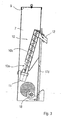
- the slide ramp 12 is connected to a first end of a duct means 17d, for example having the shape of a pipe ending in a downwards "U" shaped section and having a second end connected to fan means 18 suitable to send into the duct means 17d cold air coming from the environment external to the heating means 1.
- a duct means 17d for example having the shape of a pipe ending in a downwards "U" shaped section and having a second end connected to fan means 18 suitable to send into the duct means 17d cold air coming from the environment external to the heating means 1.
- fan means 18 suitable to send into the duct means 17d cold air coming from the environment external to the heating means 1.
- the cold air sent into the slide ramp 12 according to the way shown by the arrows in Figure 3 along the duct means 17d prevents the pellets 8 into it from the possibility of overheating, due to the hot air penetrating into the slide ramp 12 from the combustion chamber 2, up to reach the combustion temperature, propagating the combustion to the pellets contained into the Archimedean screw 10 and those contained into the tank 7.
- the first end of the duct means 17d can also be connected, instead of to the slide ramp 12, to the Archimedean screw 10, so that the cold air coming from the duct means 17d is sent to the Archimedean screw 10 and, from there, to the slide ramp 12.
- the container means 7 is arranged with respect to the stove 1 so as to define between the wall 14a thereof and the corresponding wall 7a of the container means 7 a hollow space 7c into which the duct means 17d can pass and in case also an air flow which draws heat from the wall 14a and brings it in the environment under the action of the fan 18.
- an insert for fire-places includes a body 20 into which a combustion chamber 2a has been obtained subject to be loaded with wood that can be introduced into the combustion chamber 2a through an opening 3, accessible through a shutter 4a.
- the smokes produced by the combustion are ejected through a first opening 22, obtained on the top of body 20, which can be connected to the smoke pipe of the fire-place in order to connect the combustion chamber 2a with an environment external to the room to be heated.
- the shape and the dimensions of the body 20 are such that the same body can be inserted into a fire-place.
- Container means 23 suitable to contain pellets of wood shows a load opening (not represented) suitable to allow the loading of pellets into the container means 23.
- the container means 23 has shape and dimensions such as to be insertable in a fire-place together the above-mentioned body 20.
- the pellets are subject to be transferred from the container means 23 to the combustion chamber 2a through an Archimedean screw 24 driven by a motor-reducer 25.
- the Archimedean screw 24 is suitable to draw the pellets from a bottom region of the container means 23 and to bring them to the top of a slide ramp 26, which is suitable to drive the fall of the pellets, towards a brazier 27 placed inside the combustion chamber 2a.
- the slide ramp 26 results partially introduced into the combustion chamber 2a through a hole 28 made on a lateral surface 29 thereof.
- the slide ramp 26 is connected to a first end of a further duct means 30 whose second end is connected to fan means 31 suitable to send into the further duct means 30 cold air coming from the external environment.
- the cold air sent into the slide ramp 26 prevents the pellets inside it from the overheating, due to the hot air which penetrates into the slide ramp 26 from the combustion chamber 2a, up to reach the combustion temperature, propagating the combustion to the pellets contained into the Archimedean screw 24 and those contained into the tank 23.
- the first end of the further duct means 30 can also be connected, instead of to the slide ramp 26, to the Archimedean screw 24, so as the cold air coming from the fan 31 is sent to the Archimedean screw 24 and, from there, to the slide ramp 26.
- a pipe 33 is obtained into which air drawn from the environment external to the body 20 is sent, through suction means 32, for example fans.
- suction means 32 for example fans.
- This air, passing through the pipe 33 is heated as a consequence of the heat transmitted into the pipe 33 through the walls of the combustion chamber 2a and is reintroduced into the environment from which it was drawn through some openings 34, for examples slots, obtained on the upper portion of the body 20, for example on the upper portion of the shutter 4a.
- a drawer 35 is obtained for the collection of the ashes produced by the combustion of the fuel material.
- An electric control device (not shown), in case including an electronic board, placed on an external surface of the body 20 or the container means 23, allows the user to start the feeding of the pellets, to stop it, or to regulate it and to select a desired temperature level into the room to be heated.
Landscapes
- Engineering & Computer Science (AREA)
- Chemical & Material Sciences (AREA)
- Combustion & Propulsion (AREA)
- Mechanical Engineering (AREA)
- General Engineering & Computer Science (AREA)
- Solid-Fuel Combustion (AREA)
- Resistance Heating (AREA)
- Yarns And Mechanical Finishing Of Yarns Or Ropes (AREA)
- Air-Conditioning For Vehicles (AREA)
Abstract
Description
- The invention relates to heating means in order to heat residential rooms.
- The prior art includes wood-burning stoves provided with a combustion chamber which is loaded with firewood through an opening, that can be closed by a shutter, obtained on a side wall delimiting a combustion chamber. The smokes produced by the wood combustion are ejected through a smoke pipe communicating the combustion chamber to the exterior.
- A defect of such devices results from the used fuel type, whose combustion causes a relative high production of carbon monoxide which is responsible of environmental problems such as the rising of the average temperature of our planet due to the so-called greenhouse effect. A further defect is found in the high amount of solid residual combustion products which force the user to accomplish frequent and tiring cleaning operations.
- Heating devices are furthermore known which use as fuel the so-called "pellets" of wood. These pellets are obtained from residual products of the wood working (sawdust or chips) which are subjected to a high pressure in order to obtain compact products having a substantially cylindrical shape. The pellets are obtained without the use of polluting additives; they are characterized by a very low humidity percentage and therefore they burn easily. The combustion of such products furthermore produces a rather low amount of solid residual products; also the production of carbon monoxide results equally low. Furthermore, the synthesis of carbon dioxide (CO2) during the combustion appears compatible with the environmental requirements. Devices which use the pellets as fuel comprise a combustion chamber delimited by a wall on which an opening is obtained that can be closed by a shutter. At the interior of the combustion chamber is accommodated a brazier designed to receive the pellets in order to contain them while burning.
- These devices work at forced circulation, i.e. they present, upward to the combustion chamber, a suction and smokes unloading chamber provided with a fan suitable to intake the smokes themselves and to produce a vacuum pressure needed to create an air flow inside the combustion chamber essential in order to cause that the pellets can burn. Instead a smoke pipe does not appear as necessary as in the usual wood-burning stoves due to the low production of CO2 generated by the combustion of the pellets. A further fan, placed in a lower region of the device, draws air from the external environment and conveys it along a suitable path so as air is heated and again admitted into the external environment. A fuel tank, near the combustion chamber, is suitable to contain a high amount of pellets so as to assure to the device a considerable working duration. The fuel loading into the brazier results through a screw conveyor (driven by a motor-reducer) which draws the pellets from a bottom region of the tank in order to convey them inside the combustion chamber in a region above the brazier. From this last region, a slide ramp of suitable length drives the fuel fall into the brazier. The apparatus can be furthermore equipped with an electronic board suitable to accomplish different operations such as the ignition, the putting out and the selection of a stated temperature. The keeping of the desired temperature and of a suitable pressure inside the combustion chamber is accomplished by devices as pressure and thermo-swithces that interact with the fans and the motor-reducer.
- DE 3226877 discloses a boiler, suitable for alternative or joint combustion of wood chippings and/or sawdust and pieces of wood, provided with a combustion chamber to which a conveying device, a combustion-air supply device, an exhaust fume conduit and a hot-air exchange device are connected. The combustion chamber has a combustion grille that occupies from 40% to 80% of the transverse section of the combustion chamber, the conveying device leads into a loading hopper that occupies the section surface of the combustion chamber kept free by the grille. In addition to the conveying device, there is provided an opening for manual filling on the side and/or top wall of the combustion chamber.
- The above-mentioned devices can not properly work while accomplishing the combustion of other types of fuel such as the natural wood; in effect the excessive amount of CO2 produced could not be delivered without a smoke pipe.
- In the pellets burning devices there is the risk that the high temperature present in the combustion chamber can produce the combustion of the pellets already on the slide ramp which conveys them onto the brazier, with the eventuality of the combustion propagation to the pellets present into the screw conveyor and from here to the pellets contained in the tank near the combustion chamber, with consequent risk of propagation of fire.
- Apparatus for the heating of rooms are furthermore known, the so-called fire-places, constituted by a hearth open toward the room to be heated, wherein the fuel to be burnt is placed, generally pieces of wood, and a smoke pipe for the unloading of the smokes produced by the combustion. These devices have a very low efficiency, because a large amount of the heat produced by the combustion is wasted through the smoke pipe. Furthermore they do not allow to use fuel in small pieces, such as the wood pellets.
- A heating means according to the preamble of
claim 1 is known from DE-U-9218953. - An object of the present invention is to improve the known means for the heating of residential rooms.
- A further object is to make more versatile the known means for the heating of residential rooms.
- Another object of the present invention is to make more safe the above-mentioned means for the heating of residential rooms.
- Still another object of the present invention is to improve the efficiency of the fire-places.
- These objects are achieved by a heating means according to
claim 1. - The first fuel materials can be pieces of natural wood, while the second fuel materials can be pellets of wood, solid fuels of small size, or granular, for example fuel materials shattered as olive-stones brushed and shattered, walnut-shells, or hazel-nuts, or other else.
- In such manner, it is possible to accomplish, with a same apparatus, either the combustion of wood, either the combustion of pellets or similar.
- In a particularly advantageous version, the combustion chamber and the container means constitute two distinct units interconnected by the conveyor means.
- The conveyor means advantageously includes in a first section screw conveyor means and possibly in a second section a slide ramp suitable to drive the fall of the pellets into a brazier of the combustion chamber.
- Therefore, in case one of the two units is out of work, for example the container means, it is possible to substitute such unit while continuing to use the other one (the combustion chamber). In this way the substitution involves relatively low costs.
- In a further version, the means for heating of rooms is constituted by a single unit and the combustion chamber and the container means are separated by a dividing wall.
- In this manner the apparatus results easy transportable. The container means may be provided suitable to contain solid, granular fuel materials and conveyor means of said solid, granular fuel materials which is suitable to convey said granular, solid fuel materials between said container means and a combustion chamber.
- That allows to accomplish the means for the heating of rooms according to the invention by using a pre-existing normal wood stove to which a hole has been made for the insertion of the conveyor means.
- In a particularly advantageous version, the set of the heating means and the container means presents such shape and dimensions that it can be inserted into the hearth of a fire-place.
- In such a manner the efficiency of the fire-place is particularly improved.
- The means for the heating of rooms is provided including a combustion chamber provided with an inlet arranged to introduce first fuel materials in said combustion chamber, an outlet through which combustion smokes can leave said combustion chamber, and includes furthermore cooling means suitable to cool said further fuel means in said conveyor means.
- In this way it is possible to hold the temperature of the further fuel materials, during their transfer to the combustion chamber, considerably below their combustion temperature, preventing the risk that their combustion starts while still inside the conveyor means and can propagate to the container means.
- That makes the heating means particularly safe.
- The invention could be better understood and put into practice with reference to the enclosed drawings, which show, for nonlimiting example purpose, some embodiment thereof, wherein:
- Figure 1 is a schematic perspective view of a stove according to the invention;
- Figure 2 is schematic view, like that in Figure 1, but in a version provided with cooling means;
- Figure 3 is a vertical section of container means according to the invention;
- Figure 4 is a front view of an insert for fire-place;
- Figure 5 is the V-V section of Figure 4;
- A
domestic stove 1 includes acombustion chamber 2 suitable to be loaded withwood 3 that can be introduced into thecombustion chamber 2 through an opening 4. The air heated by the combustion of thewood 3 propagates to the environment to be heated throughoutlet slot 5, obtained at the top of thecombustion chamber 2, besides by irradiation. The smokes produced by the combustion, containing a high amount of CO2, are ejected through asmoke pipe 6 which connects thecombustion chamber 2 to an environment external to the room to be heated. - Container means 7 suitable to contain pellets 8 shows a
loading opening 9 obtained at the top of the container means 7 and suitable to allow the loading of pellets 8 inside the container means 7. - The pellets 8 are subject to be conveyed from the container means 7 to the
combustion chamber 2 through an Archimedeanscrew conveyor 10 driven by a motor-reducer 11 (Figure 2). The Archimedeanscrew conveyor 10 is suitable to draw the pellets 8 from a bottom region of the container means 7 through amouth 10a (Figure 3) provided in a bottom region of a covering 10b of the Archimedeanscrew conveyor 10. The pellets drawn through themouth 10a are transferred to the top of a gravity duct, or slide ramp, 12 which is suitable to drive the fall of the pellets 8 toward abrazier 13 placed at the inner side of thecombustion chamber 2. Theslide ramp 12 results partially introduced into thecombustion chamber 2 through ahole 14 made on a lateral surface 14a thereof. - An
electrical control device 15, in case including an electronic board, placed on anexternal covering surface 17a of the container means 7, allows the user to start up theapparatus 1, to turn off it and to select a desired temperature level. - Pressure and thermo-switches, if any, not shown, allow the control of the temperature into the heated rooms. A
shutter 16 placed on a lateral surface of thecombustion chamber 2 can include a glass slab in order to allow a better irradiation and the visual control of the interior of thechamber 2 and results suitable to be opened in order to allow the periodical cleaning operations. - In a version not shown, the container means can pour out the second fuel 8 into the
combustion chamber 2 by fall through a star-valve that can be driven in automatic, semi-automatic or manual way. - As shown in Figure 2, the
slide ramp 12 is connected to a first end of a duct means 17d, for example having the shape of a pipe ending in a downwards "U" shaped section and having a second end connected to fan means 18 suitable to send into the duct means 17d cold air coming from the environment external to the heating means 1. It is to be understood that the adoption of the fan means 18 is preferential, but not essential, because, during the working, thecombustion chamber 2 lies in light depression due to the draft of the smokes and therefore cold air is anyhow sucked through the duct means 17d and cools theslide ramp 12 and the material contained therein, if any. - The cold air sent into the
slide ramp 12 according to the way shown by the arrows in Figure 3 along the duct means 17d prevents the pellets 8 into it from the possibility of overheating, due to the hot air penetrating into theslide ramp 12 from thecombustion chamber 2, up to reach the combustion temperature, propagating the combustion to the pellets contained into theArchimedean screw 10 and those contained into thetank 7. - It is furthermore noted that, in case of forced draft, the risk that the pellets 8 into the
slide ramp 12 and theArchimedean screw 10 can overheat is very reduced, because the forced draft opposes the penetration of the hot air into theslide ramp 12. In this case the duct means 17d and thefan 18, if any, have the function of safety elements, in order to prevent the overheating of the pellets 8 in the case that the forced draft stops. It is noticed, with reference to this, that anyhow the forced draft is not necessary for the correct working of the stove according to the invention. - The first end of the duct means 17d can also be connected, instead of to the
slide ramp 12, to theArchimedean screw 10, so that the cold air coming from the duct means 17d is sent to theArchimedean screw 10 and, from there, to theslide ramp 12. - The container means 7 is arranged with respect to the
stove 1 so as to define between the wall 14a thereof and the corresponding wall 7a of the container means 7 ahollow space 7c into which the duct means 17d can pass and in case also an air flow which draws heat from the wall 14a and brings it in the environment under the action of thefan 18. - As shown in Figures 4 and 5, an insert for fire-places includes a
body 20 into which acombustion chamber 2a has been obtained subject to be loaded with wood that can be introduced into thecombustion chamber 2a through anopening 3, accessible through ashutter 4a. The smokes produced by the combustion are ejected through afirst opening 22, obtained on the top ofbody 20, which can be connected to the smoke pipe of the fire-place in order to connect thecombustion chamber 2a with an environment external to the room to be heated. The shape and the dimensions of thebody 20 are such that the same body can be inserted into a fire-place. - Container means 23 suitable to contain pellets of wood shows a load opening (not represented) suitable to allow the loading of pellets into the container means 23. The container means 23 has shape and dimensions such as to be insertable in a fire-place together the above-mentioned
body 20. - The pellets are subject to be transferred from the container means 23 to the
combustion chamber 2a through anArchimedean screw 24 driven by a motor-reducer 25. TheArchimedean screw 24 is suitable to draw the pellets from a bottom region of the container means 23 and to bring them to the top of aslide ramp 26, which is suitable to drive the fall of the pellets, towards abrazier 27 placed inside thecombustion chamber 2a. - The
slide ramp 26 results partially introduced into thecombustion chamber 2a through ahole 28 made on alateral surface 29 thereof. - The
slide ramp 26 is connected to a first end of a further duct means 30 whose second end is connected to fan means 31 suitable to send into the further duct means 30 cold air coming from the external environment. - The cold air sent into the
slide ramp 26 prevents the pellets inside it from the overheating, due to the hot air which penetrates into theslide ramp 26 from thecombustion chamber 2a, up to reach the combustion temperature, propagating the combustion to the pellets contained into theArchimedean screw 24 and those contained into thetank 23. - The first end of the further duct means 30 can also be connected, instead of to the
slide ramp 26, to theArchimedean screw 24, so as the cold air coming from thefan 31 is sent to theArchimedean screw 24 and, from there, to theslide ramp 26. Inside thebody 20, outside thecombustion chamber 2a, apipe 33 is obtained into which air drawn from the environment external to thebody 20 is sent, through suction means 32, for example fans. This air, passing through thepipe 33 is heated as a consequence of the heat transmitted into thepipe 33 through the walls of thecombustion chamber 2a and is reintroduced into the environment from which it was drawn through someopenings 34, for examples slots, obtained on the upper portion of thebody 20, for example on the upper portion of theshutter 4a. Downwards thecombustion chamber 2a adrawer 35 is obtained for the collection of the ashes produced by the combustion of the fuel material. - An electric control device (not shown), in case including an electronic board, placed on an external surface of the
body 20 or the container means 23, allows the user to start the feeding of the pellets, to stop it, or to regulate it and to select a desired temperature level into the room to be heated. - Possible pressure and thermo-switches not represented allow the temperature control into the heated rooms.
Claims (12)
- Heating means for heating domestic environments, including a combustion chamber (2, 2a) provided with inlet means (14, 28) arranged to introduce therein fuel means (8), said combustion chamber (2, 2a) being suitable to receive, through further inlet means (4, 4a) further fuel means (3), non necessarily of the same type, dimension, or shape of said fuel means (8), conveyor means (10, 12; 24, 26) arranged for transferring said fuel means (8) in said combustion chamber (2,2a), characterized in that said conveyor means (10, 12; 26, 24) is provided with cooling means (17d ; 30) leading into said conveyor means (10,12,26,24) so as to bring fresh air in contact with said fuel means (8) therein.
- Heating means according to claim 1, wherein said combustion chamber (2, 2a) is suitable to receive said further fuel means in shape of pieces of natural wood (3).
- Heating means according to claim 1, or 2, and further comprising container means (7, 23) for said fuel means (8) provided with said conveyor means (10, 24) arranged in order to transfer said fuel means (8) in said combustion chamber (2, 2a).
- Heating means according to claim 3, wherein said container means (7, 23) forms with said combustion chamber (2, 2a) a single heating unit.
- Heating means according to any preceding claim, wherein said combustion chamber (2, 2a) is suitable to receive said fuel means selected in a group including: wood pellets (8), olive-stones brushed and shattered, walnut-shells, or hazelnut shells.
- Heating means according to any preceding claim wherein said conveyor means comprises screw conveyor means (10, 24).
- Heating means according to any preceding claim, wherein said conveyor means includes a star-valve.
- Heating means according to any preceding claim, wherein said conveyor means further comprises slide ramp means (12, 26) suitable to drive the fall of said fuel means (8) in a brazier (13, 27) contained in said combustion chamber (2).
- Heating means according to any preceding claim, and having dimensions and shape such that it can be inserted into a hearth of a fire-place.
- Heating means according to any preceding claim, wherein said cooling means includes pipe means (17d, 30) leading at one end into an outlet region of said conveyor means (10, 24).
- Heating means according to claim 10, wherein, near said end, said pipe means (17d, 30) is "U" shaped downwards.
- Heating means according to claim 10, or 11, wherein said pipe means (17d, 30) has another end associated to fan means (18, 31) suitable to blow room air toward said end.
Applications Claiming Priority (6)
| Application Number | Priority Date | Filing Date | Title |
|---|---|---|---|
| IT1998MO000181 IT1306347B1 (en) | 1998-08-19 | 1998-08-19 | Heater for use in residential rooms comprises combustion chamber loaded with wood to be burnt and outlet exhaust and shutter at the lateral surface of the chamber |
| ITMO980181 | 1998-08-19 | ||
| ITMO980220 IT1304915B1 (en) | 1998-10-26 | 1998-10-26 | Heater for use in residential rooms comprises combustion chamber loaded with wood to be burnt and outlet exhaust and shutter at the lateral surface of the chamber |
| ITMO980221 IT1304916B1 (en) | 1998-10-26 | 1998-10-26 | Heater for use in residential rooms comprises combustion chamber loaded with wood to be burnt and outlet exhaust and shutter at the lateral surface of the chamber |
| ITMO980221 | 1998-10-26 | ||
| ITMO980220 | 1998-10-26 |
Publications (3)
| Publication Number | Publication Date |
|---|---|
| EP0985883A2 EP0985883A2 (en) | 2000-03-15 |
| EP0985883A3 EP0985883A3 (en) | 2004-01-07 |
| EP0985883B1 true EP0985883B1 (en) | 2006-05-24 |
Family
ID=27274127
Family Applications (1)
| Application Number | Title | Priority Date | Filing Date |
|---|---|---|---|
| EP99116096A Expired - Lifetime EP0985883B1 (en) | 1998-08-19 | 1999-08-17 | Heating means |
Country Status (4)
| Country | Link |
|---|---|
| EP (1) | EP0985883B1 (en) |
| AT (1) | ATE327479T1 (en) |
| DE (1) | DE69931440T2 (en) |
| ES (1) | ES2263242T3 (en) |
Families Citing this family (13)
| Publication number | Priority date | Publication date | Assignee | Title |
|---|---|---|---|---|
| SE9903777L (en) * | 1999-10-20 | 2001-01-29 | Energifraagan Ab | Vertical screw feeder feeder for a particle and stove burner with such feeder |
| ITUD20020064A1 (en) * | 2002-03-18 | 2003-09-18 | Palazzetti Lelio Spa | HEATING DEVICE WITH DOUBLE FUEL SUPPLY |
| DE10254565B4 (en) * | 2002-11-21 | 2005-02-03 | Hark Gmbh & Co. Kg Kamin- Und Kachelofenbau | Stove and its use |
| ITVI20040252A1 (en) * | 2004-10-22 | 2005-01-22 | Lorenzo Verlato | FIREPLACE INSERT STOVE WITH FUEL LOADING THROUGH A FRONT SLIDE |
| DE102006009811B4 (en) * | 2006-03-01 | 2008-05-29 | Isabell Koppe | heater |
| DE102007010919A1 (en) * | 2007-03-05 | 2008-10-30 | Viessmann Werke Gmbh & Co Kg | Fuel tank has housing with base side, where chamber is provided with base having deepest point inclined towards base side in housing for receiving solid fuel |
| ITVI20080013A1 (en) * | 2008-01-23 | 2009-07-24 | Thermorossi Spa | HEATING APPLIANCES AS STOVES, PELLET THERMOSTATS. |
| EP2103872A1 (en) * | 2008-03-17 | 2009-09-23 | Jørn Pøhl Christensen | Wood burning stove with wood pellet burner |
| AT511145B1 (en) | 2011-03-14 | 2014-03-15 | Riener Karl Stefan | METHOD FOR REGULATING A HEATING DEVICE |
| FR3038034B1 (en) * | 2015-06-24 | 2019-04-26 | Invicta Group | SOLID FUEL STOVE AND POWER SUPPLY MODULE OF SUCH STOVE |
| IT201800007325A1 (en) * | 2018-07-19 | 2020-01-19 | PELLET OR BIOMASS BOILER | |
| WO2022236098A1 (en) * | 2021-05-06 | 2022-11-10 | Halo Products Group, Llc | Pellet heater |
| FR3163998A1 (en) * | 2024-06-27 | 2026-01-02 | Woodmood | Wood-burning stove including storage means for storing fuel in the form of logs |
Family Cites Families (2)
| Publication number | Priority date | Publication date | Assignee | Title |
|---|---|---|---|---|
| DE3226877A1 (en) * | 1982-07-17 | 1984-01-19 | Albert 6200 Wiesbaden Wagner | Heating boiler |
| DE9218953U1 (en) * | 1991-02-19 | 1996-05-23 | Riener, Karl Stefan, Micheldorf | Solid fuel furnace, especially pellets |
-
1999
- 1999-08-17 EP EP99116096A patent/EP0985883B1/en not_active Expired - Lifetime
- 1999-08-17 ES ES99116096T patent/ES2263242T3/en not_active Expired - Lifetime
- 1999-08-17 AT AT99116096T patent/ATE327479T1/en not_active IP Right Cessation
- 1999-08-17 DE DE69931440T patent/DE69931440T2/en not_active Expired - Fee Related
Also Published As
| Publication number | Publication date |
|---|---|
| ATE327479T1 (en) | 2006-06-15 |
| DE69931440D1 (en) | 2006-06-29 |
| EP0985883A2 (en) | 2000-03-15 |
| ES2263242T3 (en) | 2006-12-01 |
| EP0985883A3 (en) | 2004-01-07 |
| DE69931440T2 (en) | 2006-11-30 |
Similar Documents
| Publication | Publication Date | Title |
|---|---|---|
| EP0985883B1 (en) | Heating means | |
| US5429110A (en) | Mobile pellet stove with thermal barrier and ventilated firepot | |
| US5137012A (en) | Pellet burning stove | |
| US5347977A (en) | Combination of a baking oven and a stove | |
| JP5568394B2 (en) | Incinerator | |
| WO1984002385A1 (en) | A solid fuel stoker | |
| US4470358A (en) | Continuous solid fuel-bed degasification burner apparatus | |
| KR101134044B1 (en) | Firewood and pellet combination stove | |
| CN203404807U (en) | Energy-saving environment-friendly biomass automatic deslagging water heating cooking stove | |
| US3930491A (en) | Combination fireplace and space heater | |
| US20230371744A1 (en) | Pellet oven with negative pressure combustion | |
| JP2005121337A (en) | Wooden solid fuel supply system | |
| KR100825822B1 (en) | Grate of solid fuel heater | |
| US4506653A (en) | Combustion method and apparatus | |
| JP3155768U (en) | Hot air heater | |
| CA2280478A1 (en) | Heating means | |
| JP4044431B2 (en) | Pellet fuel combustion equipment | |
| CN219229654U (en) | Temperature Controlled Charcoal Furnace | |
| KR101823535B1 (en) | Burning system for air circulation type using pellet fuel and the method therefor | |
| JP2005121336A (en) | Heating system | |
| CN105485661A (en) | Lower feeding biomass smokeless multi-purpose furnace capable of directly combusting crushed straw | |
| JP2009041788A (en) | Woody pellet combustion device | |
| CN207268446U (en) | Energy-saving combustion apparatus | |
| KR102742890B1 (en) | Pellet stove capable of complete combustion of pellets by eddy current formation in a narrow combustor | |
| GB2530668A (en) | Stove |
Legal Events
| Date | Code | Title | Description |
|---|---|---|---|
| PUAI | Public reference made under article 153(3) epc to a published international application that has entered the european phase |
Free format text: ORIGINAL CODE: 0009012 |
|
| AK | Designated contracting states |
Kind code of ref document: A2 Designated state(s): AT BE CH CY DE DK ES FI FR GB GR IE IT LI LU MC NL PT SE |
|
| AX | Request for extension of the european patent |
Free format text: AL;LT;LV;MK;RO;SI |
|
| EL | Fr: translation of claims filed | ||
| PUAL | Search report despatched |
Free format text: ORIGINAL CODE: 0009013 |
|
| AK | Designated contracting states |
Kind code of ref document: A3 Designated state(s): AT BE CH CY DE DK ES FI FR GB GR IE IT LI LU MC NL PT SE |
|
| AX | Request for extension of the european patent |
Extension state: AL LT LV MK RO SI |
|
| RIC1 | Information provided on ipc code assigned before grant |
Ipc: 7F 24B 1/02 B Ipc: 7F 24B 13/04 A |
|
| 17P | Request for examination filed |
Effective date: 20040707 |
|
| 17Q | First examination report despatched |
Effective date: 20040817 |
|
| AKX | Designation fees paid |
Designated state(s): AT BE CH CY DE DK ES FI FR GB GR IE IT LI LU MC NL PT SE |
|
| AXX | Extension fees paid |
Extension state: RO Payment date: 20040707 Extension state: AL Payment date: 20040707 |
|
| GRAP | Despatch of communication of intention to grant a patent |
Free format text: ORIGINAL CODE: EPIDOSNIGR1 |
|
| GRAS | Grant fee paid |
Free format text: ORIGINAL CODE: EPIDOSNIGR3 |
|
| GRAA | (expected) grant |
Free format text: ORIGINAL CODE: 0009210 |
|
| AK | Designated contracting states |
Kind code of ref document: B1 Designated state(s): AT BE CH CY DE DK ES FI FR GB GR IE IT LI LU MC NL PT SE |
|
| AX | Request for extension of the european patent |
Extension state: AL RO |
|
| PG25 | Lapsed in a contracting state [announced via postgrant information from national office to epo] |
Ref country code: FI Free format text: LAPSE BECAUSE OF FAILURE TO SUBMIT A TRANSLATION OF THE DESCRIPTION OR TO PAY THE FEE WITHIN THE PRESCRIBED TIME-LIMIT Effective date: 20060524 |
|
| REG | Reference to a national code |
Ref country code: GB Ref legal event code: FG4D |
|
| REG | Reference to a national code |
Ref country code: CH Ref legal event code: EP |
|
| REG | Reference to a national code |
Ref country code: IE Ref legal event code: FG4D |
|
| REF | Corresponds to: |
Ref document number: 69931440 Country of ref document: DE Date of ref document: 20060629 Kind code of ref document: P |
|
| PG25 | Lapsed in a contracting state [announced via postgrant information from national office to epo] |
Ref country code: IE Free format text: LAPSE BECAUSE OF NON-PAYMENT OF DUE FEES Effective date: 20060817 |
|
| PG25 | Lapsed in a contracting state [announced via postgrant information from national office to epo] |
Ref country code: SE Free format text: LAPSE BECAUSE OF FAILURE TO SUBMIT A TRANSLATION OF THE DESCRIPTION OR TO PAY THE FEE WITHIN THE PRESCRIBED TIME-LIMIT Effective date: 20060824 Ref country code: DK Free format text: LAPSE BECAUSE OF FAILURE TO SUBMIT A TRANSLATION OF THE DESCRIPTION OR TO PAY THE FEE WITHIN THE PRESCRIBED TIME-LIMIT Effective date: 20060824 |
|
| PG25 | Lapsed in a contracting state [announced via postgrant information from national office to epo] |
Ref country code: MC Free format text: LAPSE BECAUSE OF NON-PAYMENT OF DUE FEES Effective date: 20060831 |
|
| REG | Reference to a national code |
Ref country code: CH Ref legal event code: PFA Owner name: EUROFIAMMA S.R.L. Free format text: EUROFIAMMA S.R.L.#VIA CHIESA, 15#43024 NEVIANO DEGLI ARDUINI PARMA (IT) -TRANSFER TO- EUROFIAMMA S.R.L.#VIA RAFFAELLO SANZIO 136#27036 MORTARA (PAVIA) (IT) Ref country code: CH Ref legal event code: NV Representative=s name: FIAMMENGHI-FIAMMENGHI |
|
| PG25 | Lapsed in a contracting state [announced via postgrant information from national office to epo] |
Ref country code: PT Free format text: LAPSE BECAUSE OF FAILURE TO SUBMIT A TRANSLATION OF THE DESCRIPTION OR TO PAY THE FEE WITHIN THE PRESCRIBED TIME-LIMIT Effective date: 20061024 |
|
| ET | Fr: translation filed | ||
| REG | Reference to a national code |
Ref country code: ES Ref legal event code: FG2A Ref document number: 2263242 Country of ref document: ES Kind code of ref document: T3 |
|
| REG | Reference to a national code |
Ref country code: FR Ref legal event code: CA |
|
| PLBE | No opposition filed within time limit |
Free format text: ORIGINAL CODE: 0009261 |
|
| STAA | Information on the status of an ep patent application or granted ep patent |
Free format text: STATUS: NO OPPOSITION FILED WITHIN TIME LIMIT |
|
| GBPC | Gb: european patent ceased through non-payment of renewal fee |
Effective date: 20060824 |
|
| 26N | No opposition filed |
Effective date: 20070227 |
|
| PG25 | Lapsed in a contracting state [announced via postgrant information from national office to epo] |
Ref country code: GB Free format text: LAPSE BECAUSE OF NON-PAYMENT OF DUE FEES Effective date: 20060824 |
|
| BECA | Be: change of holder's address |
Owner name: *EUROFIAMMA S.R.L.VIA RAFFAELLO SANZIO 136, I-2703 Effective date: 20060524 |
|
| PG25 | Lapsed in a contracting state [announced via postgrant information from national office to epo] |
Ref country code: GR Free format text: LAPSE BECAUSE OF FAILURE TO SUBMIT A TRANSLATION OF THE DESCRIPTION OR TO PAY THE FEE WITHIN THE PRESCRIBED TIME-LIMIT Effective date: 20060825 |
|
| PG25 | Lapsed in a contracting state [announced via postgrant information from national office to epo] |
Ref country code: LU Free format text: LAPSE BECAUSE OF NON-PAYMENT OF DUE FEES Effective date: 20060817 |
|
| PGFP | Annual fee paid to national office [announced via postgrant information from national office to epo] |
Ref country code: NL Payment date: 20080728 Year of fee payment: 10 Ref country code: ES Payment date: 20080818 Year of fee payment: 10 Ref country code: DE Payment date: 20080901 Year of fee payment: 10 Ref country code: CH Payment date: 20080728 Year of fee payment: 10 |
|
| PG25 | Lapsed in a contracting state [announced via postgrant information from national office to epo] |
Ref country code: CY Free format text: LAPSE BECAUSE OF FAILURE TO SUBMIT A TRANSLATION OF THE DESCRIPTION OR TO PAY THE FEE WITHIN THE PRESCRIBED TIME-LIMIT Effective date: 20060524 |
|
| PGFP | Annual fee paid to national office [announced via postgrant information from national office to epo] |
Ref country code: AT Payment date: 20080725 Year of fee payment: 10 |
|
| PG25 | Lapsed in a contracting state [announced via postgrant information from national office to epo] |
Ref country code: IT Free format text: LAPSE BECAUSE OF NON-PAYMENT OF DUE FEES Effective date: 20070817 |
|
| REG | Reference to a national code |
Ref country code: NL Ref legal event code: V1 Effective date: 20100301 Ref country code: CH Ref legal event code: PL |
|
| PG25 | Lapsed in a contracting state [announced via postgrant information from national office to epo] |
Ref country code: LI Free format text: LAPSE BECAUSE OF NON-PAYMENT OF DUE FEES Effective date: 20090831 Ref country code: CH Free format text: LAPSE BECAUSE OF NON-PAYMENT OF DUE FEES Effective date: 20090831 |
|
| PG25 | Lapsed in a contracting state [announced via postgrant information from national office to epo] |
Ref country code: AT Free format text: LAPSE BECAUSE OF NON-PAYMENT OF DUE FEES Effective date: 20090817 |
|
| PG25 | Lapsed in a contracting state [announced via postgrant information from national office to epo] |
Ref country code: NL Free format text: LAPSE BECAUSE OF NON-PAYMENT OF DUE FEES Effective date: 20100301 Ref country code: DE Free format text: LAPSE BECAUSE OF NON-PAYMENT OF DUE FEES Effective date: 20100302 |
|
| REG | Reference to a national code |
Ref country code: ES Ref legal event code: FD2A Effective date: 20090818 |
|
| PGFP | Annual fee paid to national office [announced via postgrant information from national office to epo] |
Ref country code: FR Payment date: 20100910 Year of fee payment: 12 |
|
| PGFP | Annual fee paid to national office [announced via postgrant information from national office to epo] |
Ref country code: BE Payment date: 20100825 Year of fee payment: 12 |
|
| PGFP | Annual fee paid to national office [announced via postgrant information from national office to epo] |
Ref country code: IT Payment date: 20100823 Year of fee payment: 12 |
|
| PGRI | Patent reinstated in contracting state [announced from national office to epo] |
Ref country code: IT Effective date: 20110616 |
|
| PG25 | Lapsed in a contracting state [announced via postgrant information from national office to epo] |
Ref country code: ES Free format text: LAPSE BECAUSE OF NON-PAYMENT OF DUE FEES Effective date: 20090818 |
|
| BERE | Be: lapsed |
Owner name: *EUROFIAMMA S.R.L. Effective date: 20110831 |
|
| REG | Reference to a national code |
Ref country code: FR Ref legal event code: ST Effective date: 20120430 |
|
| PG25 | Lapsed in a contracting state [announced via postgrant information from national office to epo] |
Ref country code: IT Free format text: LAPSE BECAUSE OF NON-PAYMENT OF DUE FEES Effective date: 20110817 Ref country code: BE Free format text: LAPSE BECAUSE OF NON-PAYMENT OF DUE FEES Effective date: 20110831 |
|
| PG25 | Lapsed in a contracting state [announced via postgrant information from national office to epo] |
Ref country code: FR Free format text: LAPSE BECAUSE OF NON-PAYMENT OF DUE FEES Effective date: 20110831 |