EP0985878B1 - Gas burner for cooking stove - Google Patents
Gas burner for cooking stove Download PDFInfo
- Publication number
- EP0985878B1 EP0985878B1 EP98900408A EP98900408A EP0985878B1 EP 0985878 B1 EP0985878 B1 EP 0985878B1 EP 98900408 A EP98900408 A EP 98900408A EP 98900408 A EP98900408 A EP 98900408A EP 0985878 B1 EP0985878 B1 EP 0985878B1
- Authority
- EP
- European Patent Office
- Prior art keywords
- gas
- burner
- inlet
- stove
- chamber
- Prior art date
- Legal status (The legal status is an assumption and is not a legal conclusion. Google has not performed a legal analysis and makes no representation as to the accuracy of the status listed.)
- Expired - Lifetime
Links
- 238000010411 cooking Methods 0.000 title 1
- 230000004907 flux Effects 0.000 claims description 3
- 238000004512 die casting Methods 0.000 claims description 2
- 238000010276 construction Methods 0.000 description 17
- 238000002485 combustion reaction Methods 0.000 description 11
- 230000009467 reduction Effects 0.000 description 10
- 238000005192 partition Methods 0.000 description 8
- 230000008901 benefit Effects 0.000 description 5
- 230000009471 action Effects 0.000 description 2
- 230000008859 change Effects 0.000 description 2
- 230000008602 contraction Effects 0.000 description 2
- 230000000087 stabilizing effect Effects 0.000 description 2
- 230000003292 diminished effect Effects 0.000 description 1
- 230000000694 effects Effects 0.000 description 1
- 239000011521 glass Substances 0.000 description 1
- 238000010438 heat treatment Methods 0.000 description 1
- 230000002093 peripheral effect Effects 0.000 description 1
- 230000004044 response Effects 0.000 description 1
Images


Classifications
-
- F—MECHANICAL ENGINEERING; LIGHTING; HEATING; WEAPONS; BLASTING
- F24—HEATING; RANGES; VENTILATING
- F24C—DOMESTIC STOVES OR RANGES ; DETAILS OF DOMESTIC STOVES OR RANGES, OF GENERAL APPLICATION
- F24C3/00—Stoves or ranges for gaseous fuels
- F24C3/08—Arrangement or mounting of burners
- F24C3/085—Arrangement or mounting of burners on ranges
-
- F—MECHANICAL ENGINEERING; LIGHTING; HEATING; WEAPONS; BLASTING
- F23—COMBUSTION APPARATUS; COMBUSTION PROCESSES
- F23D—BURNERS
- F23D14/00—Burners for combustion of a gas, e.g. of a gas stored under pressure as a liquid
- F23D14/02—Premix gas burners, i.e. in which gaseous fuel is mixed with combustion air upstream of the combustion zone
- F23D14/04—Premix gas burners, i.e. in which gaseous fuel is mixed with combustion air upstream of the combustion zone induction type, e.g. Bunsen burner
- F23D14/06—Premix gas burners, i.e. in which gaseous fuel is mixed with combustion air upstream of the combustion zone induction type, e.g. Bunsen burner with radial outlets at the burner head
- F23D14/065—Premix gas burners, i.e. in which gaseous fuel is mixed with combustion air upstream of the combustion zone induction type, e.g. Bunsen burner with radial outlets at the burner head with injector axis inclined to the burner head axis
-
- F—MECHANICAL ENGINEERING; LIGHTING; HEATING; WEAPONS; BLASTING
- F23—COMBUSTION APPARATUS; COMBUSTION PROCESSES
- F23D—BURNERS
- F23D2212/00—Burner material specifications
- F23D2212/20—Burner material specifications metallic
-
- F—MECHANICAL ENGINEERING; LIGHTING; HEATING; WEAPONS; BLASTING
- F23—COMBUSTION APPARATUS; COMBUSTION PROCESSES
- F23D—BURNERS
- F23D2213/00—Burner manufacture specifications
-
- Y—GENERAL TAGGING OF NEW TECHNOLOGICAL DEVELOPMENTS; GENERAL TAGGING OF CROSS-SECTIONAL TECHNOLOGIES SPANNING OVER SEVERAL SECTIONS OF THE IPC; TECHNICAL SUBJECTS COVERED BY FORMER USPC CROSS-REFERENCE ART COLLECTIONS [XRACs] AND DIGESTS
- Y02—TECHNOLOGIES OR APPLICATIONS FOR MITIGATION OR ADAPTATION AGAINST CLIMATE CHANGE
- Y02E—REDUCTION OF GREENHOUSE GAS [GHG] EMISSIONS, RELATED TO ENERGY GENERATION, TRANSMISSION OR DISTRIBUTION
- Y02E20/00—Combustion technologies with mitigation potential
- Y02E20/34—Indirect CO2mitigation, i.e. by acting on non CO2directly related matters of the process, e.g. pre-heating or heat recovery
Definitions
- This invention relates to a gas burner for a stove, and more particularly to a design for avoiding, by means of a simple construction, an extinguishment occurring when the quantity of gas is reduced rapidly from large fire to small fire.
- an ordinary gas burner for a stove can adjust the quantity of gas from a large fire of about 2,700-4,000kcal/h to a small fire of about 300-450kcal/h.
- air corresponding to the quantity of gas spouting from a nozzle is drawn by an ejector pump action caused by a flow velocity of the gas spouting from the nozzle.
- Primary air (about 50% of theoretical air) necessary for combustion is drawn.
- a large quantity of primary air is drawn according to the quantity of gas.
- Such conventional burners are known from JP 5-61614 U and from JP 5-52519 U.
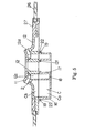
- a diaphragm 8 is provided at a forward end of a branch passage 7 branched from a gas passage 13 extending to a nozzle 6 for jetting gas into a mixing tube 55, to form an expansion/contraction chamber 9 which expands and contracts under gas pressures transmitted.
- the expansion/contraction chamber 9 expands as a result of a pressure drop, to push the gas stored through the branch passage 7 out to the gas passage 13, thereby to compensate for a lack in the gas flow rate due to the rapid throttle-down.
- Numeral 30 in the drawing denotes a valve for adjusting the quantity of gas.
- a damper for adjusting primary air for a burner is turned in response to a movement of a control lever for adjusting the quantity of gas.
- the quantity of primary air In time of throttling to a state of small fire, the quantity of primary air also is throttled down.
- the damper to be pivotable, and a complicated structure for its interlocking with the control lever, which lowers assembling facility.
- the prior art has the problems of requiring movable parts, and of complicated construction and assembly, high cost and low productivity.
- This invention intends to solve such problems, and its object is to provide a gas burner for a stove which has a simple construction for avoiding extinguishment when the quantity of gas is reduced rapidly from large fire to small fire, and which dispenses with movable parts, simplifies the construction, stabilizes its function, improves productivity, and achieves a cost reduction.
- a gas burner for a stove according to this invention is defined in claim 1.
- said inlet and said outlet are arranged such that a direction of introduction of said mixed gas introduced from said inlet into said sub-chamber is different from a direction extending from said inlet to said outlet.
- a cross-sectional area of the inlet is made larger than a cross-sectional area of the outlet.
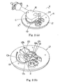
- Fig. 1 (a) shows an overall perspective view of a gas burner A for a stove according to this invention, and Fig. 1 (b) shows a perspective view with a burner cap 11 removed.
- Fig. 2 (a) shows a perspective view of the back of gas burner A for a stove, and Fig. 2 (b) shows a perspective view of the back of a main burner body 12 with a mixing tube 5 removed.
- Fig. 3 (a) shows a sectional view of mixing tube 5, and Fig. 3 (b) a plan view of mixing tube 5.
- this gas burner A for a stove is incorporated into a built-in stove or the like incorporated into a system kitchen.
- the gas burner A for a stove includes a gas burner 1 and a mixing tube 5.
- the gas burner 1 has a main burner body 12 and a burner cap 11.
- the mixing tube 5 is coupled to the main burner body 12 in a sealed manner.
- the various components such as the gas burner 1, mixing tube 5 and burner cap 11 are formed by aluminum-pressure die-casting.
- the burner cap 11 which is approximately umbrella-shaped, has a bore 11a formed centrally thereof for guiding secondary air, and an engaging cylinder 11b extending downward when the burner cap 11 is mounted on the main burner body 12.
- the burner cap 11 has, on the back thereof, inner circumferential partitions 11c and outer circumferential partitions 11d formed at intervals in the circumferential direction. Lower surfaces of inner circumferential partitions 11c and lower surfaces of outer circumferential partitions 11d are inclined to turn outward as they extend from the center toward the peripheries.
- the main burner body 12 is approximately disc-shaped, and has an inner cylindrical element 12a formed centrally thereof and supported by a connector 12b.
- the inner cylindrical element 12a allows passage of secondary air through an interior space thereof.
- a first gas passage 12c is formed circumferentially of the inner cylindrical element 12a.
- a mixed gas is supplied from the mixing tube 5 to the first gas passage 12c.
- a top surface of the main burner body 12 is inclined downward toward the center.
- the lower surfaces of inner circumferential partitions 11c and the lower surfaces of outer circumferential partitions 11d of the burner cap 11 are placed on the inclined surface 12d.
- the mixed gas from the first gas passage 12c passes between the inner circumferential partitions 11c and outer circumferential partitions 11d to be pushed out of flame holes 4 formed in peripheral positions between the main burner body 12 and burner cap 11.
- the mixed gas is ignited in an ignition chamber 14 formed in a part in the circumferential direction between the burner cap 11 and main burner body 12, to burn at the flame holes 4 distributed in the circumferential direction.
- the ignition chamber 14 includes an ignition device 23 having a spark plug 24 and a spark target 25.
- the inner cylindrical element 12a of the main burner body 12 has a projection 12e formed on an upper surface thereof.
- the bore 11a of the burner cap 11 includes a small-diameter bore portion 11e formed therein. This small-diameter bore portion lie is engaged with the projection 12e to position the burner cap 11 circumferentially relative to the main burner body 12.
- the mixing tube 5 has, disposed at one end thereof, a nozzle 6, and a damper for adjusting the intake quantity of primary air.
- the other end of mixing tube 5 has a case 16 with an open top formed integral therewith.
- the case 16 includes a cylindrical element 17 extending vertically therethrough. An approximately C-shaped second gas passage 18 is formed around the cylindrical element 17.
- the second gas passage 18 is vertically opposed to the first gas passage 12c of the main burner body 12.
- the first gas passage 12c and second gas passage 18 are collectively called a gas passage.
- a lower sub-chamber Ca is formed radially outwardly of the first gas passage 12c of main burner body 12 through an inlet 3 in the form of a slit.
- the main burner body 12 has a caulking edge 19 projecting in the form of a ridge from a lower surface thereof and fitting with an outer circumferential shape of case 16.
- An engaging projection 20 is formed also on the lower surface of main burner body 12 for positioning the case 16.
- the case 16 is rigidly connected to the main burner body 12 in a sealed manner by fitting an engaging recess 21 of the case 16 with the engaging projection 20, engaging the outer periphery of case 16 inside the caulking edge 19 in the form of a ridge to envelop a projection 22 (flange) formed on an outer surface at the opening side of case 16, and deforming the caulking edge 19.
- the inner cylindrical element 12a of main burner body 12 also has a caulking edge 12f formed on an inner, lower surface thereof. The caulking edge 12f is deformable to establish a sealed connection with the cylindrical element 17 of the case 16.
- the nozzle 6 is provided for said mixing tube 5.
- Gas is introduced in jet from the nozzle 6.
- primary air is drawn into the mixing tube 5 by way of the damper (not shown) for varying the area of a primary air intake port to change the quantity of primary air drawn in.
- the gas and primary air are mixed in the mixing tube 5.
- This mixed gas passes from the mixing tube 5 through the case 16, and through the first gas passage 12c in the main burner body 12, to the lower surface of burner cap 11 to be spouted from the flame holes 4 while being ignited by said ignition device 23 in the ignition chamber 14 to burn.
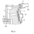
- the main burner body 12 has a recessed upper sub-chamber Cb opposed to the lower sub-chamber Ca of the case 16.
- the vertically opposed upper and lower sub-chambers Ca, Cb constitute a sub-chamber C.
- An outlet 2 in the form of two slits is opened, in an inward position of the upper sub-chamber Cb, in the inclined surface 12d of the main burner body 12 opposed to the burner cap.
- the sub-chamber C having the inlet 3 for introducing the mixed gas of gas and primary air from the mixing tube 5, and the outlet 2 for letting out the mixed gas, is formed integral with the gas burner 1, and the outlet 2 is formed adjacent the flame holes 4 of the gas burner 1.
- the sub-chamber C is formed as a hollow chamber disposed arcuately and radially outwardly of the first gas passage 12c and second gas passage 18 with respect to the center of the gas burner 1 which is approximately circular.
- the sub-chamber C communicates with the first gas passage 12c only through one inlet 3.
- the mixed gas supplied from the mixing tube 5 collides with the cylindrical element 17 of the case 16, to have the strength of flow diminished.
- the gas is introduced through the inlet 3 in slit form, the inlet 3 having a direction of introduction set such that the mixed gas introduced does not flow directly toward the outlet 2. That is, said inlet 3 and said outlet 2 are arranged such that the direction of introduction of said mixed gas introduced from said inlet 3 into said sub-chamber C is different from a direction extending from said inlet 3 to said outlet.
- the air-rich mixed gas in time of the reduction to a small fire takes a roundabout way to the outlet 2, without being supplied to the inlet 3 to short-circuit to the flame holes 4, to back up effectively the preceding mixed gas having the mixing ratio for the state of large fire.
- the mixed gas having the mixing ratio for the state of large fire is delivered through the outlet 2.
- the inlet 3 has a cross-sectional area larger than the cross-sectional area of outlet 2, so that the mixed gas flow out of the outlet 2 steadily.
- a top board 26 formed of glass is supported between an outer edge of main burner body 12 and an annular presser ring 27. The top board 26 is fixed in place by attaching the presser ring 27 to the main burner body 12 with screws 28.
- the gas burner for a stove according to the invention in this application includes a sub-chamber having an inlet for introducing said mixed gas from at least one of said mixing tube and said gas passage, and an outlet disposed adjacent said flame holes, and storing said mixed gas in a state of flux.
- the mixing tube receives an air-rich mixed gas having a small quantity of gas and primary air introduced in a large quantity by inertia.
- Such an air-rich mixed gas is introduced into the sub-chamber to push a mixed gas stored in the sub-chamber and having a mixing ratio for a large fire, out of the outlet of the sub-chamber to the flame holes.
- the sub-chamber is formed integral with the gas burner, to dispense with the movable parts used conventionally, simplify the construction, improve assembly and productivity, and achieve a cost reduction. Having no movable parts provides an advantage of stabilizing combustion.
- said inlet and said outlet are arranged such that the direction of introduction of a mixed gas introduced from the inlet into the sub-chamber is different from the direction extending from the inlet to the outlet. Then, an air-rich mixed gas in time of a reduction to a small fire takes a roundabout way in the sub-chamber to the outlet, without being supplied to the inlet to short-circuit to the flame holes. This provides an advantage of fulfilling the object of this invention with increased effect.
- the sub-chamber is never decompressed rapidly, which provides an advantage of stabilizing the flow to the outlet.
- the inlet 3 of sub-chamber C communicates only with the gas passage C.
Landscapes
- Engineering & Computer Science (AREA)
- Chemical & Material Sciences (AREA)
- Combustion & Propulsion (AREA)
- Mechanical Engineering (AREA)
- General Engineering & Computer Science (AREA)
- Gas Burners (AREA)
Applications Claiming Priority (3)
| Application Number | Priority Date | Filing Date | Title |
|---|---|---|---|
| JP00729897A JP3711182B2 (ja) | 1997-01-20 | 1997-01-20 | コンロ用ガスバーナ |
| JP729897 | 1997-01-20 | ||
| PCT/JP1998/000161 WO1998031967A1 (en) | 1997-01-20 | 1998-01-16 | Gas burner for cooking stove |
Publications (3)
| Publication Number | Publication Date |
|---|---|
| EP0985878A1 EP0985878A1 (en) | 2000-03-15 |
| EP0985878A4 EP0985878A4 (en) | 2000-08-09 |
| EP0985878B1 true EP0985878B1 (en) | 2003-04-16 |
Family
ID=11662128
Family Applications (1)
| Application Number | Title | Priority Date | Filing Date |
|---|---|---|---|
| EP98900408A Expired - Lifetime EP0985878B1 (en) | 1997-01-20 | 1998-01-16 | Gas burner for cooking stove |
Country Status (5)
| Country | Link |
|---|---|
| US (1) | US6089219A (enExample) |
| EP (1) | EP0985878B1 (enExample) |
| JP (1) | JP3711182B2 (enExample) |
| AU (1) | AU6990398A (enExample) |
| WO (1) | WO1998031967A1 (enExample) |
Families Citing this family (35)
| Publication number | Priority date | Publication date | Assignee | Title |
|---|---|---|---|---|
| USD439801S1 (en) | 2000-02-14 | 2001-04-03 | Dutro Company | Burner with wind ring |
| AU2001241569A1 (en) | 2000-02-15 | 2001-08-27 | Travis Industries, Inc. | Burner assembly for a gas-burning fireplace |
| USD468963S1 (en) | 2002-02-11 | 2003-01-21 | Lucas Pai | Stove ring |
| ITMI20020315A1 (it) * | 2002-02-18 | 2003-08-18 | Sabaf Spa | Piano di cottura in vetro temprato o altro materiale termicamente degradabile |
| US6854139B2 (en) * | 2002-07-26 | 2005-02-15 | Sheila Lamy | Bed covering fastening system |
| FR2848642B1 (fr) * | 2002-12-17 | 2005-08-05 | Service Nat Dit Gaz De France | Bruleur a gaz a flamme interne, de compacite elevee |
| US6935328B2 (en) * | 2003-06-13 | 2005-08-30 | General Electric Company | Method and apparatuses for gas ranges |
| MY147945A (en) * | 2004-02-02 | 2013-02-15 | Electrolux Ab | Gas burner |
| KR100715615B1 (ko) | 2005-09-14 | 2007-05-07 | 린나이코리아 주식회사 | 렌지용 버너 |
| US8302593B2 (en) * | 2005-12-30 | 2012-11-06 | General Electric Company | Gas burner assembly including inner and outer burners and methods for implementing same |
| KR100776446B1 (ko) * | 2006-12-20 | 2007-11-16 | 엘지전자 주식회사 | 가열조리기기 및 그 가열조리기기의 버너 시스템 |
| USD604097S1 (en) * | 2007-11-15 | 2009-11-17 | Glem Gas S.P.A. | Kitchen cooktop |
| US7614877B2 (en) * | 2007-12-20 | 2009-11-10 | General Electric Company | Device and method for a gas burner |
| US9022780B2 (en) * | 2008-10-27 | 2015-05-05 | Electrolux Home Products, Inc. | Oval burner alignment method |
| EP2743589B1 (de) * | 2012-12-12 | 2016-10-26 | BSH Hausgeräte GmbH | Kochgerät mit Brenner |
| JP6072563B2 (ja) * | 2013-02-21 | 2017-02-01 | 株式会社ハーマン | ガスバーナー |
| JP6178670B2 (ja) * | 2013-08-23 | 2017-08-09 | 株式会社ハーマン | ガスバーナー |
| US9951959B2 (en) * | 2013-12-20 | 2018-04-24 | Bsh Home Appliances Corporation | Home appliance with improved burner |
| USD787041S1 (en) | 2015-09-17 | 2017-05-16 | Whirlpool Corporation | Gas burner |
| US10837651B2 (en) | 2015-09-24 | 2020-11-17 | Whirlpool Corporation | Oven cavity connector for operating power accessory trays for cooking appliance |
| US11777190B2 (en) | 2015-12-29 | 2023-10-03 | Whirlpool Corporation | Appliance including an antenna using a portion of appliance as a ground plane |
| US10145568B2 (en) | 2016-06-27 | 2018-12-04 | Whirlpool Corporation | High efficiency high power inner flame burner |
| CN107514635A (zh) * | 2016-12-28 | 2017-12-26 | 中山古奇诺智能厨房有限公司 | 一种上进风燃气灶燃烧器 |
| US10551056B2 (en) | 2017-02-23 | 2020-02-04 | Whirlpool Corporation | Burner base |
| US10451290B2 (en) | 2017-03-07 | 2019-10-22 | Whirlpool Corporation | Forced convection steam assembly |
| US10660162B2 (en) | 2017-03-16 | 2020-05-19 | Whirlpool Corporation | Power delivery system for an induction cooktop with multi-output inverters |
| CN107477615A (zh) * | 2017-10-06 | 2017-12-15 | 洪余衡 | 上浮卡槽式全上进风灶具炉煲及灶具 |
| EP3775693A4 (en) | 2018-03-27 | 2021-12-22 | SCP Holdings, an Assumed Business Name of Nitride Igniters, LLC. | HOT SURFACE IGNITION DEVICES FOR COOKING PLATES |
| US10627116B2 (en) | 2018-06-26 | 2020-04-21 | Whirlpool Corporation | Ventilation system for cooking appliance |
| US10619862B2 (en) | 2018-06-28 | 2020-04-14 | Whirlpool Corporation | Frontal cooling towers for a ventilation system of a cooking appliance |
| US10837652B2 (en) | 2018-07-18 | 2020-11-17 | Whirlpool Corporation | Appliance secondary door |
| CN110925760B (zh) * | 2019-12-27 | 2025-03-07 | 贾钰 | 一种虹吸式自增压喷火炉芯及使用方法 |
| CN111140889A (zh) * | 2020-01-19 | 2020-05-12 | 浙江博立灶具科技有限公司 | 涡轮炉壳 |
| JP7359737B2 (ja) * | 2020-04-16 | 2023-10-11 | リンナイ株式会社 | コンロ用バーナ並びにガスコンロ |
| USD1063523S1 (en) * | 2023-02-25 | 2025-02-25 | Dongsheng Zhou | Gas burner assembly |
Family Cites Families (7)
| Publication number | Priority date | Publication date | Assignee | Title |
|---|---|---|---|---|
| JPH0336418A (ja) * | 1989-06-29 | 1991-02-18 | Harman Co Ltd | ガス流量制御装置 |
| US5002038A (en) * | 1989-12-12 | 1991-03-26 | Robert Shaw Controls Company | Burner construction and method of making the same |
| FR2659724B1 (fr) * | 1990-03-15 | 1992-07-17 | Sourdillon Sa | Bruleur a gaz, notamment pour appareil menager, agence pour etre premuni contre les effets de fluctuations importantes de la pression de l'air primaire. |
| JP2502851B2 (ja) * | 1991-08-29 | 1996-05-29 | 浜松ホトニクス株式会社 | 物体の形状および位置の測定装置 |
| JPH0561614A (ja) * | 1991-08-30 | 1993-03-12 | Fuji Facom Corp | デイスクシステムの制御方法 |
| JPH0552519U (ja) * | 1991-12-20 | 1993-07-13 | 株式会社日立ホームテック | ガスバーナ |
| JPH0561614U (ja) * | 1992-01-24 | 1993-08-13 | 株式会社日立ホームテック | ガスバーナ |
-
1997
- 1997-01-20 JP JP00729897A patent/JP3711182B2/ja not_active Expired - Lifetime
-
1998
- 1998-01-16 WO PCT/JP1998/000161 patent/WO1998031967A1/ja not_active Ceased
- 1998-01-16 US US09/341,380 patent/US6089219A/en not_active Expired - Fee Related
- 1998-01-16 AU AU69903/98A patent/AU6990398A/en not_active Abandoned
- 1998-01-16 EP EP98900408A patent/EP0985878B1/en not_active Expired - Lifetime
Also Published As
| Publication number | Publication date |
|---|---|
| JPH10205716A (ja) | 1998-08-04 |
| EP0985878A1 (en) | 2000-03-15 |
| AU6990398A (en) | 1998-08-07 |
| US6089219A (en) | 2000-07-18 |
| WO1998031967A1 (en) | 1998-07-23 |
| EP0985878A4 (en) | 2000-08-09 |
| JP3711182B2 (ja) | 2005-10-26 |
Similar Documents
| Publication | Publication Date | Title |
|---|---|---|
| EP0985878B1 (en) | Gas burner for cooking stove | |
| EP1781989B1 (en) | Gas burner with multiple flame rings | |
| US5899681A (en) | Atmospheric gas burner assembly for improved flame retention and stability | |
| EP1838997B1 (en) | Gas burner for cooking appliances | |
| WO2008112933A1 (en) | Fuel selectable heating devices | |
| KR100341252B1 (ko) | 동적안정성을개선하기위한확산파일롯을갖는대기가스버너 | |
| EP3404324A1 (en) | Burner cap of burner used for gas cooktop, burner head, burner, and gas cooktop | |
| US5765542A (en) | Cooktop gas burner | |
| KR100518487B1 (ko) | 가스제어장치 | |
| CN213929538U (zh) | 燃气阀及燃气灶 | |
| US3822982A (en) | Gas burner structure | |
| US5067651A (en) | Fuel control device, fuel control system using the device and method of making the device | |
| US9915427B2 (en) | Dual fuel pilot light burner | |
| US20200271314A1 (en) | Gas burner, gas burner assembly and domestic cooking appliance | |
| CN110848689B (zh) | 一种上进风燃烧器 | |
| CN222416066U (zh) | 用于燃气烹饪器具的燃气阀 | |
| CN217274118U (zh) | 一种用于燃气灶的燃烧器 | |
| JP2000205519A (ja) | 携帯用ガスコンロのバ―ナ―構造 | |
| CN114251488B (zh) | 燃气阀及燃气灶 | |
| KR19990013677A (ko) | 곤로버너 | |
| US4921161A (en) | Fuel control device, fuel control system using the device and method of making the device | |
| US4813596A (en) | Fuel control device, fuel control system using the device and method of making the device | |
| US3850370A (en) | Gaseous fuel burner system | |
| JPH045873Y2 (enExample) | ||
| CN118423685A (zh) | 阀门长明火装置 |
Legal Events
| Date | Code | Title | Description |
|---|---|---|---|
| PUAI | Public reference made under article 153(3) epc to a published international application that has entered the european phase |
Free format text: ORIGINAL CODE: 0009012 |
|
| 17P | Request for examination filed |
Effective date: 19990730 |
|
| AK | Designated contracting states |
Kind code of ref document: A1 Designated state(s): IT |
|
| A4 | Supplementary search report drawn up and despatched |
Effective date: 20000626 |
|
| AK | Designated contracting states |
Kind code of ref document: A4 Designated state(s): IT |
|
| RIC1 | Information provided on ipc code assigned before grant |
Free format text: 7F 23D 14/06 A, 7F 24C 3/08 B |
|
| GRAH | Despatch of communication of intention to grant a patent |
Free format text: ORIGINAL CODE: EPIDOS IGRA |
|
| GRAH | Despatch of communication of intention to grant a patent |
Free format text: ORIGINAL CODE: EPIDOS IGRA |
|
| GRAA | (expected) grant |
Free format text: ORIGINAL CODE: 0009210 |
|
| RAP1 | Party data changed (applicant data changed or rights of an application transferred) |
Owner name: HARMAN PRO CO., LTD. |
|
| AK | Designated contracting states |
Designated state(s): IT |
|
| PLBE | No opposition filed within time limit |
Free format text: ORIGINAL CODE: 0009261 |
|
| STAA | Information on the status of an ep patent application or granted ep patent |
Free format text: STATUS: NO OPPOSITION FILED WITHIN TIME LIMIT |
|
| 26N | No opposition filed |
Effective date: 20040119 |
|
| PG25 | Lapsed in a contracting state [announced via postgrant information from national office to epo] |
Ref country code: IT Free format text: LAPSE BECAUSE OF NON-PAYMENT OF DUE FEES Effective date: 20050116 |
|
| PGRI | Patent reinstated in contracting state [announced from national office to epo] |
Ref country code: IT Effective date: 20091201 |
|
| PGFP | Annual fee paid to national office [announced via postgrant information from national office to epo] |
Ref country code: IT Payment date: 20160125 Year of fee payment: 19 |
|
| PG25 | Lapsed in a contracting state [announced via postgrant information from national office to epo] |
Ref country code: IT Free format text: LAPSE BECAUSE OF NON-PAYMENT OF DUE FEES Effective date: 20170116 |