EP0985866B1 - Fitting für ein Rohr - Google Patents
Fitting für ein Rohr Download PDFInfo
- Publication number
- EP0985866B1 EP0985866B1 EP99116548A EP99116548A EP0985866B1 EP 0985866 B1 EP0985866 B1 EP 0985866B1 EP 99116548 A EP99116548 A EP 99116548A EP 99116548 A EP99116548 A EP 99116548A EP 0985866 B1 EP0985866 B1 EP 0985866B1
- Authority
- EP
- European Patent Office
- Prior art keywords
- fitting
- fitting body
- longitudinal axis
- tool
- pipe
- Prior art date
- Legal status (The legal status is an assumption and is not a legal conclusion. Google has not performed a legal analysis and makes no representation as to the accuracy of the status listed.)
- Expired - Lifetime
Links
- 229920003023 plastic Polymers 0.000 claims abstract description 9
- 239000004033 plastic Substances 0.000 claims abstract description 9
- 239000000463 material Substances 0.000 claims description 5
- 239000002184 metal Substances 0.000 abstract description 4
- 230000003313 weakening effect Effects 0.000 description 3
- 230000007797 corrosion Effects 0.000 description 2
- 238000005260 corrosion Methods 0.000 description 2
- 230000006378 damage Effects 0.000 description 2
- 238000004519 manufacturing process Methods 0.000 description 1
- 239000002905 metal composite material Substances 0.000 description 1
- 238000007789 sealing Methods 0.000 description 1
- 230000007704 transition Effects 0.000 description 1
Images

Classifications
-
- F—MECHANICAL ENGINEERING; LIGHTING; HEATING; WEAPONS; BLASTING
- F16—ENGINEERING ELEMENTS AND UNITS; GENERAL MEASURES FOR PRODUCING AND MAINTAINING EFFECTIVE FUNCTIONING OF MACHINES OR INSTALLATIONS; THERMAL INSULATION IN GENERAL
- F16L—PIPES; JOINTS OR FITTINGS FOR PIPES; SUPPORTS FOR PIPES, CABLES OR PROTECTIVE TUBING; MEANS FOR THERMAL INSULATION IN GENERAL
- F16L15/00—Screw-threaded joints; Forms of screw-threads for such joints
Definitions
- the invention relates to a fitting to which to manufacture a pipe connection a pipe, especially plastic or plastic-metal composite pipe can be connected is.
- the invention relates to such Fitting made of plastic.
- the invention has for its object a fitting create, where the risk of uselessness in Screw on to another unit in the pipe system is reduced.
- the invention provides a fitting proposed with the features of claim 1.
- the subclaims refer to special configurations of the Invention.
- part of the Fittings on the purpose of twisting the fitting for screwing a tool (wrench, Pliers or the like) is attached, and the fitting body over a torque limiting device connected.
- this is a facility whose shear strength is lower than the shear strength of the fitting body. So becomes the fitting body screwed tight, so if one is exceeded by the Defined shear strength of the torque limiting device Torque emanating from the tool engaging part the connection of the tool engagement part to the fitting body canceled.
- fitting body according to the invention is therefore the Non-positive connection between the tool engagement part and selected or adjusted according to the fitting body.
- the fitting body and the tool engagement part are in one piece connected with each other by Introduction of passages, recesses, depressions in the Connection area of both elements of the fitting for one Material weakening is taken care of, like a predetermined breaking point acts and concentric around the longitudinal axis of the fitting extends.
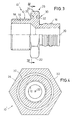
- FIGS. 1 and 2 show illustrations of a fitting 10 with a torque limit.
- the fitting 10 has one Fitting body 12 with a threaded part 14 and a pipe connection part 16 on.
- the threaded part 14 has an external thread 18 on, while the pipe connection part 16 as of the threaded part 14 protruding nozzle is formed.
- the fitting body 12 rotated about its longitudinal axis 20.
- a tool e.g. in the form of a screw connection, that to a hexagon structure 22 one normally radially projecting federal 24 is placed.
- This collar 24 forms with its hexagon structure the tool engagement part 26 of the fitting 10.
- the collar 24 and the Fitting body 12 formed in one piece.
- This predetermined breaking point zone is concentric to the longitudinal axis 20 of the fitting body 12.
- FIGS. 3 and 4 The difference of the embodiment according to FIGS. 3 and 4 compared to the fitting 10 according to FIGS. 1 and 2 exists in that the weakening of the material in the connection area of collar 24 and fitting body 12 by two facing away from each other Ring grooves 32 is achieved in opposite Directions of the longitudinal axis extension of the fitting 10 ' are open. Otherwise, in FIGS. 3 and 4 and FIGS. 1 and 2 identical or equivalent parts with the same Provide reference numerals.
Landscapes
- Engineering & Computer Science (AREA)
- General Engineering & Computer Science (AREA)
- Mechanical Engineering (AREA)
- Mutual Connection Of Rods And Tubes (AREA)
- Supports For Pipes And Cables (AREA)
- Non-Disconnectible Joints And Screw-Threaded Joints (AREA)
Description
- Fig. 1
- einen Halbschnitt durch einen Fitting gemäß einem ersten Ausführungsbeispiel der Erfindung,
- Fig. 2
- einen Schnitt entlang der Linie II-II der Fig. 1,
- Fig. 3
- einen Halbschnitt durch einen Fitting gemäß einem zweiten Ausführungsbeispiel und
- Fig. 4
- einen Schnitt entlang der Linie IV-IV der Fig. 3,
Claims (4)
- Fitting für ein Rohr mitdadurch gekennzeichnet,einem Fittingkörper (12) mit einer Längsachse (20), der einen Rohranschlussteil (16) für den dichten Anschluss eines Rohres und ein Gewinde (18) zum Verschrauben des Fittingkörpers (12) mit einer Anschlusseinheit aufweist, undeinem Werkzeugangreifteil (26) am Fittingkörper (12), an den ein Werkzeug zum Verdrehen des Fittingkörpers (12) um dessen Längsachse (20) zwecks Verschraubung mit der Anschlusseinheit ansetzbar ist,wobei zwischen dem Werkzeugangreifteil (26) und dem Fittingkörper (12) eine das bei Drehung des Werkzeugangreifteils (26) auf den Fittingkörper (12) wirkende Drehmoment begrenzende Einrichtung (30) angeordnet ist,dass die Drehmoment-Begrenzungseinrichtung (30) eine Sollbruchstellenringzone ist, die sich konzentrisch zur Längsachse (20) des Fittingkörpers (12) erstreckt und mehrere parallel zur Längsachse (20) verlaufende Durchgänge (28) oder Aussparungen oder mindestens eine zumindest abschnittsweise konzentrisch verlaufende in Erstreckung der Längsachse (20) offene Aussparung (32) aufweisen.
- Fitting nach Anspruch 1, dadurch gekennzeichnet, dass zwei Gruppen von mit ihren offenen Seiten einander abgewandten Aussparungen vorgesehen sind.
- Fitting nach Anspruch 1 oder 2, dadurch gekennzeichnet, dass die Durchgänge (28) Ringsegmentform aufweisen.
- Fitting nach einem der Ansprüche 1 bis 3, dadurch gekennzeichnet, dass der Fittingkörper (12) und insbesondere auch der Werkzeugangreifteil (26) aus Kunststoff bestehen.
Applications Claiming Priority (2)
| Application Number | Priority Date | Filing Date | Title |
|---|---|---|---|
| DE19841801 | 1998-09-12 | ||
| DE19841801A DE19841801C1 (de) | 1998-09-12 | 1998-09-12 | Fitting für ein Rohr |
Publications (2)
| Publication Number | Publication Date |
|---|---|
| EP0985866A1 EP0985866A1 (de) | 2000-03-15 |
| EP0985866B1 true EP0985866B1 (de) | 2003-02-26 |
Family
ID=7880753
Family Applications (1)
| Application Number | Title | Priority Date | Filing Date |
|---|---|---|---|
| EP99116548A Expired - Lifetime EP0985866B1 (de) | 1998-09-12 | 1999-08-24 | Fitting für ein Rohr |
Country Status (5)
| Country | Link |
|---|---|
| US (1) | US6322108B1 (de) |
| EP (1) | EP0985866B1 (de) |
| AT (1) | ATE233385T1 (de) |
| DE (1) | DE19841801C1 (de) |
| ES (1) | ES2193638T3 (de) |
Families Citing this family (42)
| Publication number | Priority date | Publication date | Assignee | Title |
|---|---|---|---|---|
| DE10034766C2 (de) * | 2000-07-18 | 2003-03-06 | Hydrometer Gmbh | Ventilzähleranschlussstück mit Drehmomentbegrenzung |
| US7833250B2 (en) | 2004-11-10 | 2010-11-16 | Jackson Roger P | Polyaxial bone screw with helically wound capture connection |
| US8377100B2 (en) * | 2000-12-08 | 2013-02-19 | Roger P. Jackson | Closure for open-headed medical implant |
| US6726687B2 (en) * | 2000-12-08 | 2004-04-27 | Jackson Roger P | Closure plug for open-headed medical implant |
| US6726689B2 (en) | 2002-09-06 | 2004-04-27 | Roger P. Jackson | Helical interlocking mating guide and advancement structure |
| US6719009B1 (en) * | 2001-02-23 | 2004-04-13 | Schwing America, Inc. | Composite material piping system |
| DE10119913A1 (de) * | 2001-04-23 | 2002-10-31 | Emhart Llc Newark | Schraubenmutter zur Begrenzung eines einwirkenden Drehmoments und dazu korrespondierendes Verfahren |
| US8876868B2 (en) | 2002-09-06 | 2014-11-04 | Roger P. Jackson | Helical guide and advancement flange with radially loaded lip |
| US8257402B2 (en) | 2002-09-06 | 2012-09-04 | Jackson Roger P | Closure for rod receiving orthopedic implant having left handed thread removal |
| US8282673B2 (en) | 2002-09-06 | 2012-10-09 | Jackson Roger P | Anti-splay medical implant closure with multi-surface removal aperture |
| FI115665B (fi) * | 2002-11-08 | 2005-06-15 | Uponor Innovation Ab | Liitoskappale |
| US7377923B2 (en) | 2003-05-22 | 2008-05-27 | Alphatec Spine, Inc. | Variable angle spinal screw assembly |
| US8137386B2 (en) | 2003-08-28 | 2012-03-20 | Jackson Roger P | Polyaxial bone screw apparatus |
| US7776067B2 (en) | 2005-05-27 | 2010-08-17 | Jackson Roger P | Polyaxial bone screw with shank articulation pressure insert and method |
| US8366753B2 (en) | 2003-06-18 | 2013-02-05 | Jackson Roger P | Polyaxial bone screw assembly with fixed retaining structure |
| US7967850B2 (en) | 2003-06-18 | 2011-06-28 | Jackson Roger P | Polyaxial bone anchor with helical capture connection, insert and dual locking assembly |
| US8398682B2 (en) | 2003-06-18 | 2013-03-19 | Roger P. Jackson | Polyaxial bone screw assembly |
| US7766915B2 (en) | 2004-02-27 | 2010-08-03 | Jackson Roger P | Dynamic fixation assemblies with inner core and outer coil-like member |
| US8936623B2 (en) | 2003-06-18 | 2015-01-20 | Roger P. Jackson | Polyaxial bone screw assembly |
| US6994355B2 (en) * | 2003-10-01 | 2006-02-07 | Infiltrator Systems Inc. | Pipe seal |
| JP2008519656A (ja) | 2004-11-10 | 2008-06-12 | ロジャー・ピー・ジャクソン | 破断伸張部付の螺旋状案内及び前進フランジ |
| US8926672B2 (en) | 2004-11-10 | 2015-01-06 | Roger P. Jackson | Splay control closure for open bone anchor |
| US9168069B2 (en) | 2009-06-15 | 2015-10-27 | Roger P. Jackson | Polyaxial bone anchor with pop-on shank and winged insert with lower skirt for engaging a friction fit retainer |
| US10076361B2 (en) | 2005-02-22 | 2018-09-18 | Roger P. Jackson | Polyaxial bone screw with spherical capture, compression and alignment and retention structures |
| JP4124257B2 (ja) * | 2006-12-12 | 2008-07-23 | ダイキン工業株式会社 | 管継手 |
| US8979904B2 (en) | 2007-05-01 | 2015-03-17 | Roger P Jackson | Connecting member with tensioned cord, low profile rigid sleeve and spacer with torsion control |
| DE102007028267B4 (de) * | 2007-06-15 | 2011-04-28 | Firep Rebar Technology Gmbh | Verbesserte Ankermutter aus faserverstärktem Kunststoff |
| FR2930805B1 (fr) * | 2008-04-30 | 2014-11-28 | Gay Pierre | Procede et organe de serrage d'un element de visserie, dispositif de fixation et de serrage |
| US11229457B2 (en) | 2009-06-15 | 2022-01-25 | Roger P. Jackson | Pivotal bone anchor assembly with insert tool deployment |
| DE102010051386A1 (de) * | 2010-11-16 | 2012-05-16 | André Kraft | Abscherbares Verbindungselement |
| US8911479B2 (en) | 2012-01-10 | 2014-12-16 | Roger P. Jackson | Multi-start closures for open implants |
| JP6071445B2 (ja) * | 2012-11-08 | 2017-02-01 | 株式会社ブリヂストン | 配管継手 |
| US8911478B2 (en) | 2012-11-21 | 2014-12-16 | Roger P. Jackson | Splay control closure for open bone anchor |
| US10058354B2 (en) | 2013-01-28 | 2018-08-28 | Roger P. Jackson | Pivotal bone anchor assembly with frictional shank head seating surfaces |
| US8852239B2 (en) | 2013-02-15 | 2014-10-07 | Roger P Jackson | Sagittal angle screw with integral shank and receiver |
| US9566092B2 (en) | 2013-10-29 | 2017-02-14 | Roger P. Jackson | Cervical bone anchor with collet retainer and outer locking sleeve |
| US9717533B2 (en) | 2013-12-12 | 2017-08-01 | Roger P. Jackson | Bone anchor closure pivot-splay control flange form guide and advancement structure |
| US9451993B2 (en) | 2014-01-09 | 2016-09-27 | Roger P. Jackson | Bi-radial pop-on cervical bone anchor |
| US10064658B2 (en) | 2014-06-04 | 2018-09-04 | Roger P. Jackson | Polyaxial bone anchor with insert guides |
| US9597119B2 (en) | 2014-06-04 | 2017-03-21 | Roger P. Jackson | Polyaxial bone anchor with polymer sleeve |
| US9651078B2 (en) * | 2014-09-23 | 2017-05-16 | Jose Ricardo Santiago-Anadon | Torque limiting fastener |
| US11215216B2 (en) * | 2018-04-27 | 2022-01-04 | Greaves Corporation | Breakaway nut |
Family Cites Families (19)
| Publication number | Priority date | Publication date | Assignee | Title |
|---|---|---|---|---|
| US1380395A (en) * | 1919-08-23 | 1921-06-07 | Louis L Korach | Lock-nut |
| US3425314A (en) * | 1967-08-09 | 1969-02-04 | John F Ohlson | Spring beam load limiting nut |
| US3504591A (en) * | 1969-01-17 | 1970-04-07 | Aeroquip Corp | Torque limiting nut |
| US3667339A (en) * | 1971-03-30 | 1972-06-06 | Richard E Dame | Friction controlled torque fastening |
| US3929054A (en) * | 1972-12-01 | 1975-12-30 | Elco Industries Inc | Fastening element adapted for tightening to predetermined torque |
| US4068555A (en) * | 1976-09-02 | 1978-01-17 | Hi-Shear Corporation | Inherently torque-limited nut |
| US4046052A (en) * | 1976-10-14 | 1977-09-06 | Solitron Devices, Inc. | Torque limiting RF connector |
| US4159667A (en) * | 1977-08-08 | 1979-07-03 | Solitron Devices, Inc. | Torque limiting RF connector |
| US4575274A (en) * | 1983-03-02 | 1986-03-11 | Gilbert Engineering Company Inc. | Controlled torque connector assembly |
| US4687392A (en) * | 1984-04-17 | 1987-08-18 | Bidwell Robert E | Torque limiting fastener |
| US4789759A (en) * | 1986-03-25 | 1988-12-06 | Amp Incorporated | Assembly for an electrical cable providing strain relief and a water-tight seal |
| FR2598855B1 (fr) * | 1986-05-14 | 1988-08-26 | Sicame Sa | Embout de vissage adhesif, cassable et jetable, a couple de vissage predetermine. |
| EP0287381A3 (de) * | 1987-04-16 | 1990-06-13 | Supedo Pty. Limited | Befestigungsvorrichtung |
| US4836727A (en) * | 1987-06-08 | 1989-06-06 | Volkmann Josef F | Torque limited pressed and forged metal nut members |
| DE9310556U1 (de) * | 1993-07-15 | 1993-09-23 | Witte, Michael, 49163 Bohmte | Schraube mit mehrkomponentigem kopf |
| AU3163995A (en) * | 1994-07-22 | 1996-02-22 | Klober, Johannes | Device to prevent excessive load |
| DE4441373C2 (de) * | 1994-11-21 | 1997-12-04 | Kirchner Fraenk Rohr | Rohrverbindung, insbesondere für Rohre mit mindestens einer Kunststoffschicht |
| US5658017A (en) * | 1995-10-03 | 1997-08-19 | Chirehdast; Mehran | Tube nut torque limiting method and apparatus |
| US5927917A (en) * | 1998-06-15 | 1999-07-27 | Gibbons; Rodney | Self-torquing nut |
-
1998
- 1998-09-12 DE DE19841801A patent/DE19841801C1/de not_active Expired - Fee Related
-
1999
- 1999-08-24 AT AT99116548T patent/ATE233385T1/de not_active IP Right Cessation
- 1999-08-24 EP EP99116548A patent/EP0985866B1/de not_active Expired - Lifetime
- 1999-08-24 ES ES99116548T patent/ES2193638T3/es not_active Expired - Lifetime
- 1999-09-10 US US09/393,157 patent/US6322108B1/en not_active Expired - Fee Related
Also Published As
| Publication number | Publication date |
|---|---|
| ES2193638T3 (es) | 2003-11-01 |
| ATE233385T1 (de) | 2003-03-15 |
| US6322108B1 (en) | 2001-11-27 |
| DE19841801C1 (de) | 2000-05-04 |
| EP0985866A1 (de) | 2000-03-15 |
Similar Documents
| Publication | Publication Date | Title |
|---|---|---|
| DE19841801C1 (de) | Fitting für ein Rohr | |
| DE2941438C2 (de) | Drehmomentbegrenzer | |
| EP1172573B1 (de) | Verdreh- und auspresssicher in ein Blech einpressbares Befestigungselement | |
| DE19820054A1 (de) | Radbefestiger | |
| EP1447576A1 (de) | Kunststoffmutter zur Aufnahme an einem einen Durchbruch aufweisenden Bauteil | |
| DE3713489A1 (de) | Gewindeelement zum verstaerken einer gewindebohrung | |
| EP0354446B1 (de) | Innengewinde-Befestigungselement | |
| DE202005017524U1 (de) | Befestigungselement für eine Reibschweißverbindung | |
| DE1400774B2 (de) | Schraubverbindung | |
| DE2818512C3 (de) | Zentralverschluß für Scheibenräder | |
| EP0634811A1 (de) | Abscherschraube | |
| DE2709084A1 (de) | Kugelgelenkverbindung und verfahren zu ihrer herstellung | |
| EP1444446B1 (de) | Befestigungssystem | |
| DE10326005A1 (de) | Abreißmutter | |
| EP0406801B1 (de) | Befestigungselement | |
| DE19948868B4 (de) | Unterlegscheibe | |
| EP0995045B1 (de) | Befestigungssystem mit einer teilweise kunststoffummantelten schraube | |
| DE3138329A1 (de) | "befestigungsanordnung" | |
| AT393542B (de) | Verbindung fuer bauteile aus unterschiedlichen materialien | |
| DE3302239A1 (de) | Verbindungselement | |
| DE102019203051A1 (de) | Befestigungselement zum Reibschweißen sowie Verfahren zum Reibschweißen eines Befestigungselements an ein flächiges Werkstück | |
| AT391002B (de) | Drehsteife, beugeelastische wellenkupplung | |
| AT401805B (de) | Befestigungsmutter, insbesondere für eine verbindungsanordnung | |
| DE4225743C2 (de) | Schutzkappe aus Kunststoff | |
| WO2002098628A2 (de) | Klemmring zum axialen verbinden von zylindrischen bauteilen |
Legal Events
| Date | Code | Title | Description |
|---|---|---|---|
| PUAI | Public reference made under article 153(3) epc to a published international application that has entered the european phase |
Free format text: ORIGINAL CODE: 0009012 |
|
| AK | Designated contracting states |
Kind code of ref document: A1 Designated state(s): AT BE CH CY DE DK ES FI FR GB GR IE IT LI LU MC NL PT SE |
|
| AX | Request for extension of the european patent |
Free format text: AL;LT;LV;MK;RO;SI |
|
| 17P | Request for examination filed |
Effective date: 20000315 |
|
| AKX | Designation fees paid |
Free format text: AT BE CH CY DE DK ES FI FR GB GR IE IT LI LU MC NL PT SE |
|
| RAP1 | Party data changed (applicant data changed or rights of an application transferred) |
Owner name: UPONOR INNOVATION AB |
|
| 17Q | First examination report despatched |
Effective date: 20011126 |
|
| GRAH | Despatch of communication of intention to grant a patent |
Free format text: ORIGINAL CODE: EPIDOS IGRA |
|
| GRAH | Despatch of communication of intention to grant a patent |
Free format text: ORIGINAL CODE: EPIDOS IGRA |
|
| GRAA | (expected) grant |
Free format text: ORIGINAL CODE: 0009210 |
|
| RBV | Designated contracting states (corrected) |
Designated state(s): AT BE CH CY DK ES FI FR GB GR IE IT LI LU MC NL PT SE |
|
| AK | Designated contracting states |
Designated state(s): AT BE CH CY DK ES FI FR GB GR IE IT LI LU MC NL PT SE |
|
| PG25 | Lapsed in a contracting state [announced via postgrant information from national office to epo] |
Ref country code: NL Free format text: LAPSE BECAUSE OF FAILURE TO SUBMIT A TRANSLATION OF THE DESCRIPTION OR TO PAY THE FEE WITHIN THE PRESCRIBED TIME-LIMIT Effective date: 20030226 Ref country code: IE Free format text: LAPSE BECAUSE OF FAILURE TO SUBMIT A TRANSLATION OF THE DESCRIPTION OR TO PAY THE FEE WITHIN THE PRESCRIBED TIME-LIMIT Effective date: 20030226 Ref country code: GR Free format text: LAPSE BECAUSE OF FAILURE TO SUBMIT A TRANSLATION OF THE DESCRIPTION OR TO PAY THE FEE WITHIN THE PRESCRIBED TIME-LIMIT Effective date: 20030226 Ref country code: GB Free format text: LAPSE BECAUSE OF FAILURE TO SUBMIT A TRANSLATION OF THE DESCRIPTION OR TO PAY THE FEE WITHIN THE PRESCRIBED TIME-LIMIT Effective date: 20030226 Ref country code: FR Free format text: LAPSE BECAUSE OF NON-PAYMENT OF DUE FEES Effective date: 20030226 Ref country code: FI Free format text: LAPSE BECAUSE OF FAILURE TO SUBMIT A TRANSLATION OF THE DESCRIPTION OR TO PAY THE FEE WITHIN THE PRESCRIBED TIME-LIMIT Effective date: 20030226 |
|
| REG | Reference to a national code |
Ref country code: GB Ref legal event code: FG4D Free format text: NOT ENGLISH |
|
| REG | Reference to a national code |
Ref country code: CH Ref legal event code: EP |
|
| REG | Reference to a national code |
Ref country code: DE Ref legal event code: 8566 |
|
| REG | Reference to a national code |
Ref country code: IE Ref legal event code: FG4D Free format text: GERMAN |
|
| PG25 | Lapsed in a contracting state [announced via postgrant information from national office to epo] |
Ref country code: SE Free format text: LAPSE BECAUSE OF FAILURE TO SUBMIT A TRANSLATION OF THE DESCRIPTION OR TO PAY THE FEE WITHIN THE PRESCRIBED TIME-LIMIT Effective date: 20030526 Ref country code: PT Free format text: LAPSE BECAUSE OF FAILURE TO SUBMIT A TRANSLATION OF THE DESCRIPTION OR TO PAY THE FEE WITHIN THE PRESCRIBED TIME-LIMIT Effective date: 20030526 Ref country code: DK Free format text: LAPSE BECAUSE OF FAILURE TO SUBMIT A TRANSLATION OF THE DESCRIPTION OR TO PAY THE FEE WITHIN THE PRESCRIBED TIME-LIMIT Effective date: 20030526 |
|
| NLV1 | Nl: lapsed or annulled due to failure to fulfill the requirements of art. 29p and 29m of the patents act | ||
| PG25 | Lapsed in a contracting state [announced via postgrant information from national office to epo] |
Ref country code: LU Free format text: LAPSE BECAUSE OF NON-PAYMENT OF DUE FEES Effective date: 20030824 Ref country code: CY Free format text: LAPSE BECAUSE OF FAILURE TO SUBMIT A TRANSLATION OF THE DESCRIPTION OR TO PAY THE FEE WITHIN THE PRESCRIBED TIME-LIMIT Effective date: 20030824 Ref country code: AT Free format text: LAPSE BECAUSE OF NON-PAYMENT OF DUE FEES Effective date: 20030824 |
|
| GBV | Gb: ep patent (uk) treated as always having been void in accordance with gb section 77(7)/1977 [no translation filed] |
Effective date: 20030226 |
|
| PG25 | Lapsed in a contracting state [announced via postgrant information from national office to epo] |
Ref country code: MC Free format text: LAPSE BECAUSE OF NON-PAYMENT OF DUE FEES Effective date: 20030831 Ref country code: LI Free format text: LAPSE BECAUSE OF NON-PAYMENT OF DUE FEES Effective date: 20030831 Ref country code: CH Free format text: LAPSE BECAUSE OF NON-PAYMENT OF DUE FEES Effective date: 20030831 Ref country code: BE Free format text: LAPSE BECAUSE OF NON-PAYMENT OF DUE FEES Effective date: 20030831 |
|
| REG | Reference to a national code |
Ref country code: IE Ref legal event code: FD4D Ref document number: 0985866E Country of ref document: IE |
|
| REG | Reference to a national code |
Ref country code: ES Ref legal event code: FG2A Ref document number: 2193638 Country of ref document: ES Kind code of ref document: T3 |
|
| PLBE | No opposition filed within time limit |
Free format text: ORIGINAL CODE: 0009261 |
|
| STAA | Information on the status of an ep patent application or granted ep patent |
Free format text: STATUS: NO OPPOSITION FILED WITHIN TIME LIMIT |
|
| EN | Fr: translation not filed | ||
| 26N | No opposition filed |
Effective date: 20031127 |
|
| BERE | Be: lapsed |
Owner name: *UPONOR INNOVATION A.B. Effective date: 20030831 |
|
| REG | Reference to a national code |
Ref country code: CH Ref legal event code: PL |
|
| PGFP | Annual fee paid to national office [announced via postgrant information from national office to epo] |
Ref country code: IT Payment date: 20120824 Year of fee payment: 14 Ref country code: ES Payment date: 20120824 Year of fee payment: 14 |
|
| PG25 | Lapsed in a contracting state [announced via postgrant information from national office to epo] |
Ref country code: IT Free format text: LAPSE BECAUSE OF NON-PAYMENT OF DUE FEES Effective date: 20130824 |
|
| REG | Reference to a national code |
Ref country code: ES Ref legal event code: FD2A Effective date: 20150407 |
|
| PG25 | Lapsed in a contracting state [announced via postgrant information from national office to epo] |
Ref country code: ES Free format text: LAPSE BECAUSE OF NON-PAYMENT OF DUE FEES Effective date: 20130825 |