EP0985487B1 - Werkzeugmaschine - Google Patents
Werkzeugmaschine Download PDFInfo
- Publication number
- EP0985487B1 EP0985487B1 EP99116152A EP99116152A EP0985487B1 EP 0985487 B1 EP0985487 B1 EP 0985487B1 EP 99116152 A EP99116152 A EP 99116152A EP 99116152 A EP99116152 A EP 99116152A EP 0985487 B1 EP0985487 B1 EP 0985487B1
- Authority
- EP
- European Patent Office
- Prior art keywords
- machine tool
- casing
- supporting structure
- elements
- vertical axis
- Prior art date
- Legal status (The legal status is an assumption and is not a legal conclusion. Google has not performed a legal analysis and makes no representation as to the accuracy of the status listed.)
- Expired - Lifetime
Links
- 238000003754 machining Methods 0.000 claims description 14
- 230000002787 reinforcement Effects 0.000 claims 7
- 230000003014 reinforcing effect Effects 0.000 claims 4
- 230000002349 favourable effect Effects 0.000 description 8
- 239000000969 carrier Substances 0.000 description 4
- 230000009286 beneficial effect Effects 0.000 description 3
- 230000015572 biosynthetic process Effects 0.000 description 3
- 238000005253 cladding Methods 0.000 description 3
- 230000000694 effects Effects 0.000 description 3
- 230000001427 coherent effect Effects 0.000 description 2
- 238000010276 construction Methods 0.000 description 2
- 238000004519 manufacturing process Methods 0.000 description 2
- 230000001154 acute effect Effects 0.000 description 1
- 239000011324 bead Substances 0.000 description 1
- 230000005540 biological transmission Effects 0.000 description 1
- 238000003745 diagnosis Methods 0.000 description 1
- 230000003028 elevating effect Effects 0.000 description 1
- 239000000463 material Substances 0.000 description 1
- 230000000149 penetrating effect Effects 0.000 description 1
- 238000000926 separation method Methods 0.000 description 1
Images



Classifications
-
- B—PERFORMING OPERATIONS; TRANSPORTING
- B23—MACHINE TOOLS; METAL-WORKING NOT OTHERWISE PROVIDED FOR
- B23Q—DETAILS, COMPONENTS, OR ACCESSORIES FOR MACHINE TOOLS, e.g. ARRANGEMENTS FOR COPYING OR CONTROLLING; MACHINE TOOLS IN GENERAL CHARACTERISED BY THE CONSTRUCTION OF PARTICULAR DETAILS OR COMPONENTS; COMBINATIONS OR ASSOCIATIONS OF METAL-WORKING MACHINES, NOT DIRECTED TO A PARTICULAR RESULT
- B23Q1/00—Members which are comprised in the general build-up of a form of machine, particularly relatively large fixed members
- B23Q1/01—Frames, beds, pillars or like members; Arrangement of ways
- B23Q1/015—Frames, beds, pillars
-
- B—PERFORMING OPERATIONS; TRANSPORTING
- B23—MACHINE TOOLS; METAL-WORKING NOT OTHERWISE PROVIDED FOR
- B23Q—DETAILS, COMPONENTS, OR ACCESSORIES FOR MACHINE TOOLS, e.g. ARRANGEMENTS FOR COPYING OR CONTROLLING; MACHINE TOOLS IN GENERAL CHARACTERISED BY THE CONSTRUCTION OF PARTICULAR DETAILS OR COMPONENTS; COMBINATIONS OR ASSOCIATIONS OF METAL-WORKING MACHINES, NOT DIRECTED TO A PARTICULAR RESULT
- B23Q39/00—Metal-working machines incorporating a plurality of sub-assemblies, each capable of performing a metal-working operation
- B23Q39/04—Metal-working machines incorporating a plurality of sub-assemblies, each capable of performing a metal-working operation the sub-assemblies being arranged to operate simultaneously at different stations, e.g. with an annular work-table moved in steps
- B23Q39/042—Metal-working machines incorporating a plurality of sub-assemblies, each capable of performing a metal-working operation the sub-assemblies being arranged to operate simultaneously at different stations, e.g. with an annular work-table moved in steps with circular arrangement of the sub-assemblies
- B23Q39/046—Metal-working machines incorporating a plurality of sub-assemblies, each capable of performing a metal-working operation the sub-assemblies being arranged to operate simultaneously at different stations, e.g. with an annular work-table moved in steps with circular arrangement of the sub-assemblies including a loading and/or unloading station
-
- Y—GENERAL TAGGING OF NEW TECHNOLOGICAL DEVELOPMENTS; GENERAL TAGGING OF CROSS-SECTIONAL TECHNOLOGIES SPANNING OVER SEVERAL SECTIONS OF THE IPC; TECHNICAL SUBJECTS COVERED BY FORMER USPC CROSS-REFERENCE ART COLLECTIONS [XRACs] AND DIGESTS
- Y10—TECHNICAL SUBJECTS COVERED BY FORMER USPC
- Y10T—TECHNICAL SUBJECTS COVERED BY FORMER US CLASSIFICATION
- Y10T82/00—Turning
- Y10T82/25—Lathe
- Y10T82/2511—Vertical
-
- Y—GENERAL TAGGING OF NEW TECHNOLOGICAL DEVELOPMENTS; GENERAL TAGGING OF CROSS-SECTIONAL TECHNOLOGIES SPANNING OVER SEVERAL SECTIONS OF THE IPC; TECHNICAL SUBJECTS COVERED BY FORMER USPC CROSS-REFERENCE ART COLLECTIONS [XRACs] AND DIGESTS
- Y10—TECHNICAL SUBJECTS COVERED BY FORMER USPC
- Y10T—TECHNICAL SUBJECTS COVERED BY FORMER US CLASSIFICATION
- Y10T82/00—Turning
- Y10T82/25—Lathe
- Y10T82/2524—Multiple
-
- Y—GENERAL TAGGING OF NEW TECHNOLOGICAL DEVELOPMENTS; GENERAL TAGGING OF CROSS-SECTIONAL TECHNOLOGIES SPANNING OVER SEVERAL SECTIONS OF THE IPC; TECHNICAL SUBJECTS COVERED BY FORMER USPC CROSS-REFERENCE ART COLLECTIONS [XRACs] AND DIGESTS
- Y10—TECHNICAL SUBJECTS COVERED BY FORMER USPC
- Y10T—TECHNICAL SUBJECTS COVERED BY FORMER US CLASSIFICATION
- Y10T82/00—Turning
- Y10T82/25—Lathe
- Y10T82/2552—Headstock
- Y10T82/2562—Spindle and bearings
-
- Y—GENERAL TAGGING OF NEW TECHNOLOGICAL DEVELOPMENTS; GENERAL TAGGING OF CROSS-SECTIONAL TECHNOLOGIES SPANNING OVER SEVERAL SECTIONS OF THE IPC; TECHNICAL SUBJECTS COVERED BY FORMER USPC CROSS-REFERENCE ART COLLECTIONS [XRACs] AND DIGESTS
- Y10—TECHNICAL SUBJECTS COVERED BY FORMER USPC
- Y10T—TECHNICAL SUBJECTS COVERED BY FORMER US CLASSIFICATION
- Y10T82/00—Turning
- Y10T82/25—Lathe
- Y10T82/2566—Bed
Definitions
- the invention relates to a machine tool Machine frame with a base and one on it seated machine stand with a support ring, one rotatable about a substantially vertical axis Support ring mounted carrier, several arranged on the carrier Workpiece holding devices for workpieces to be machined, one running around the vertical axis Work room in which the workpiece holding devices movable around the vertical axis by rotating the carrier are, and a variety of on the machine frame in the Area of the work area arranged stations, in which the workpiece holding devices during a machining cycle are positionable.
- Such machine tools are from the prior art known. Such is a machine tool, for example described in German patent application 195 04 369.3-14.
- the machine stand is provided by ribs running in radial planes to the axis, which carry the support ring.
- Such a solution is with the required rigidity only with great effort realizable.
- the core of the solution according to the invention is therefore closed see, the machine stand a great rigidity against all possible forces occurring on the support ring to lend that this by a shell surface structure trained stiffening jacket are included, which outside the work area and at least partially runs around, so that on the one hand in the azimuthal direction forces acting on the vertical axis in large Distance from the vertical axis to be caught and spread at this large radial distance from the vertical axis simply into the base frame thanks to the lateral surface structure let initiate.
- stiffening jacket When providing one that encloses the work area In principle, stiffening jacket would still be an access to that Working space in the vertical direction both from above and possible from below. However, such access is not satisfactory.
- the work space exclusively through the openings in the stiffening jacket is accessible so that the breakthroughs are sufficient Must be sized to accommodate everything required in the work space To be able to carry out manipulations, in particular in order to sufficient equipment for the individual stations To be able to carry out tools and also in a diagnosis and / or Unload the workpiece from the work area to be able to move out or into it.
- each station has a breakthrough is assigned in the stiffening jacket, so that each of the Stations are individually accessible.
- a particularly advantageous embodiment of a The machine tool according to the invention provides, for example, that the stations include processing stations and that in the tool carrier provided in each processing station is accessible from outside via one of the openings.
- the stations a Beund / or Unload station include and that in the loading and / or Unloading a workpiece transport device through the Breakthrough runs through.
- the breakthrough to be dimensioned so that the entire workpiece transport device during the operation of the machine tool can reach through the breakthrough.
- the loading station and that next to it a single breakthrough assigned to the unloading station which is, for example, over two shell structure elements could extend.
- this is expedient single breakthrough also a single shell structure element assigned.
- each of the sheath support elements is at least partially one of the Breakthroughs extends around and is therefore able to simply to direct the forces around the breakthrough and to show the required rigidity.
- each shell structure element extending areally parallel to the lateral surface includes coherent flat struts.
- the flat struts could in principle be in the form of a lattice structure or lattice support structure.
- a constructively particularly simple solution provides that the flat struts are closed within their outer contour Have surfaces, which means that they are easy to manufacture, with their flat sides parallel to the coat extending flat material parts are, however, by their Extension in the direction of the lateral surface opposite in the Forces acting surface are rigid.
- the base area any such prismatic surface can have shape.
- Base area a circular shape or a polygonal shape or at least partially a form of a regular polygon to be the basis.
- Base areas Even with a conical surface, the most different Base areas conceivable. For example, are as conceivable Base areas circular areas, polygonal areas or partially Base areas can be realized in the form of a regular polygon.
- the Shell surface has a polygonal base, which is in edges running away from the base surface in the lateral surface continues, so that the total surface area through jacket pieces extending in planes between the edges is formed, which is mechanically simple on the one hand can be realized and in particular further advantages in this regard offer that they not only have high rigidity against create forces acting in the azimuth direction, but also high rigidity against those acting transversely to the taper axis Forces.
- a particularly favorable form provides that part of the Base area of the lateral surface has the shape of a regular Has polygons, especially since a regular polygon can be conveniently adapted to a machine in which constant angular distances from each other the carrier are provided.
- the support ring in addition to the outer surface structure the underframe is held fixed by cross-frame elements is which is parallel to the vertical axis and transverse extend to the lateral surface transverse planes and in these transverse planes acting and transmitted by the support ring Take up forces resistant to deformation.
- These crossbeam elements are particularly suitable in a simple manner vertical direction and transverse to the vertical axis Absorb forces so that this results in additional stiffening of the lateral surface structure with simple means is possible and thus also the lateral surface structure of Force effects can be at least partially relieved for which this is only suitable to a limited extent.
- transverse planes parallel to radial directions to the vertical axis run, in particular in a suitable manner transverse to this absorb vertical forces.
- a particularly high stability of the cross-member elements is then reachable if these are parallel to the areas Extend transverse planes.
- transverse support elements could preferably be in Lattice or strut construction.
- crossbeam elements are formed, since with such closed Wall elements transfer high lateral forces in a simple manner let and such closed wall elements still are very easy to manufacture.
- the machine tool can therefore be implemented if the cross-member elements arranged within the lateral surface structure are, since in this case the lateral surface structure is the maximum external dimensions of the machine frame.
- stiffening struts can be reached if this is in a cross to vertical axis, because then with such stiffening struts an improved deformation stiffness of the lateral surface structure against expansion in can reach radial direction to the vertical axis.
- stiffening struts each extend up to the crossbeam elements and connected to them so that the stiffening struts not only stabilize the lateral surface structure, but at the same time also a stiffening of the crossbeam elements effect relative to each other.
- the machine stand itself were in connection with the previous explanation of individual exemplary embodiments made no further details.
- the machine stand could have any dimensions as long as this overall is adequate Deformation stiffness against all forces guaranteed.
- the deformation behavior can be particularly advantageous of the machine stand, even the largest Deformation rigidity, shape when the machine stand is dimensioned so that it is rigid has a multiple symmetry to the vertical axis, so that in particular the azimuthal direction on the support ring acting forces no asymmetrical to the vertical axis Deformation of the machine stand, but due to the multiple symmetry to the vertical axis symmetrical deformation, which especially of precision the positioning of the workpiece holding devices in the individual stations after rotating the carrier relative to Machine frame is useful.
- the workpiece receiving devices in a substantially vertical direction are movable.
- movable in a substantially vertical direction Workpiece holding devices there is the possibility Pick up workpieces from workpiece transport devices or to be placed on workpiece transport devices. This means that it is not necessarily an exclusively vertical one Movability of the workpiece holding devices necessary but the direction of movement of the workpiece receiving devices also an acute angle with the Can include verticals.
- the movements of the workpiece receiving devices relative to Carriers can basically be in any way will be realized. It is particularly favorable if the Movement of the workpiece receiving devices relative to Carrier takes place as a numerically controlled axis movement.
- the tool carriers are not with the carrier rotatably arranged on the machine frame, but with respect to the rotation of the carrier Machine frame connected. It would be, for example conceivable, the tool carrier of the machining stations on Fix machine stand.
- the machine stand from additional loads is to be kept clear by tool carriers arranged on it preferably provided that the tool holder for the tools are arranged on the base.
- the underframe Tool carrier carries.
- the tool carriers can be used in many different ways Way be trained.
- An advantageous type of Training of a tool holder provides that this as Tool slide is formed, which is a simple Position the tool relative to the respective one Processing station in which the tool for processing is available, allowed.
- the slides are preferably provided with at least one numerically controlled axis, in particular a linear axis, Mistake.
- the machine stand 40 comprises, as in FIGS. 2, 3 and 4 shown one Stiffening jacket, which in a around the axis 20 extending lateral surface 44, on the one hand from a to Axis 20 prismatic jacket section 46 and on the other hand one to the axis 20 with a cone angle ⁇ extending conical jacket section 48 is formed, lying individual cladding elements 50a to 50g having one another as a whole at 52 designated lateral surface structure are connected.
- the lateral surface 44 is preferably designed such that in the region of its prismatic lateral section 46, insofar as the lateral supporting structure elements 50a to 50f are concerned, from a base area of a regular polygon, for example as shown in FIG. 3, a base area of a regular octagon with the side edges 70 1 to 70 8 , so that the prismatic jacket section 46 rises from the regular octagon with the side edges 70 1 to 70 6 , the side edges 70 7 and 70 8 in the lateral surface 44 according to the invention, as will be explained in detail later, are missing, but the side edges 70 1 to 70 6 form the base area in the area of the shell supporting elements 50a to 50f.
- the jacket surface 44 is formed by flat surfaces extending parallel to the axis 20 and parallel to the side edges 70 1 to 70 6 , to which the wall sections 54 of the individual tensile structure elements 50 are aligned in parallel.
- the base of the regular octagon with the side edges 70 1 to 70 6 is continued in the conical jacket section 48, so that the lateral surface 44 has flat surfaces in the region of the jacket supporting structure elements 50a to 50f, each of which, on the one hand, at an angle ⁇ run to the axis 20 and on the other hand parallel to the side edges 70 1 to 70 6 of the regular octagon and connect to the surfaces of the prismatic jacket section 46 to form an edge 72 1 to 72 6 which extends azimuthally about the axis 20.
- each of the shell structure elements 50a to f then coincide with two successive edges 78 1 to 78 7 of this type .
- the sheath support element 50g In contrast to the sheath support elements 50a to 50f, the sheath support element 50g, particularly shown in FIG. 4, replaces two sections of the regular octagon which would correspond to the side edges 70 7 and 70 8 of the regular octagon.
- the lateral surface 44 therefore has a surface 82 in the region of the shell supporting structure element 50g in a plane 80 parallel to the axis 20 and passing through the corner points 74 7 and 74 1 , in which the opening 58g lies and the flat struts 54g, 60g and surrounding the opening 58g 62g and 64g, the flat strut 54g forming the lower flat strut delimiting the opening 58g, the flat struts 60g and 62g forming the side flat struts which laterally delimit the opening 58g, and the flat strut 64g forming the upper flat strut which forms the opening 58g on one Top limited.
- the extension of the lower flat strut 54g in the direction of the Axis 20 is far less than the extent of the wall section 54a to 54f of the respective shell structure elements 50a to 50f, so that the opening 58g is in the sheath support element 50g closer to the parting line 38 than the breakthroughs 58a to 58f.
- the upper flat strut is 64g of the shell structure element 50g designed so that it in the direction of the axis 20th has approximately the same extension as the upper flat struts 64a to 64f of the sheath support elements 50a to 50f.
- the lateral flat struts 62g and 60g extend with their side edges 66g and 68g up to the sections of the edges 78 7 and 78 1 which run parallel to the axis 20, but proceed at an increasing distance from the circumferential edge 72 6 and 72 1 from the ones at an angle ⁇ to the axis 20 extending portions of the edges 78 7 and 78 1 , so that between them there is a triangular wall piece 82, 84 of the shell structure elements 50g, which forms the connection to the shell structure elements 50f and 50a in this area.
- All sheath support elements 50a to 50g extend from the parting plane 38 to one recognizable in FIG. 2 and in one piece formed on the upper flat struts 64 support ring 90, which has an annular circumference around the axis 20 Recording 92 for a bearing ring 94 one later in the individually described carrier 96.
- transverse support elements 100a to 100g arranged within the jacket are provided, which extend transversely to the jacket surface 44 and are preferably arranged parallel and symmetrically to the radial planes 76 1 to 76 7 , each through the corner points 74 1 to 74 7 run through.
- the transverse support elements 100a to 100g are preferably integrally formed as one piece on the lateral surface support structure 52 and parallel to the radial planes 76 1 to 76 7 radially inward in the direction of the axis extending walls or ribs, which proceed from the parting plane 38 in the direction of the axis 20 to extend to the support ring 90 and extend radially inwards from the lateral surface support 52 so that the inner edges 102 thereof are approximately a radial distance from the axis 20, which corresponds approximately to the diameter of the receptacle 92.
- the inner edges 102 preferably run approximately parallel to the axis 20 up to projections 104 of the transverse support elements 100 which project radially inward beyond the inner edges 102 and which form receptacles 106 for conduit channels.
- the lateral surface support structure 52 is still provided near the parting plane 38 with a circumferential ring made of stiffening struts 108, which is integrally formed on this on an inner side of the outer support structure elements 50a to 50g and which is in each case on an inner side of the wall sections 54 in the form of a radially inwardly projecting bead extend from the transverse support element 100 to the transverse support element 100 and form a closed circumferential ring around the axis 20 which on the one hand follows the side edges 70 1 to 70 6 of the octagon and on the other hand between the corner points 74 7 and 74 1 of the plane 80.
- stiffening struts 108 extending stiffening struts 110 in the area of the shell support elements 50a to 50f are provided, which in each case at the level of a lower edge of the openings 58a to 58f run around the axis 20, and each on the side Connect flat struts 60g and 62g.
- stiffening struts 110 preferably also extend parallel to a plane 112, which is approximately parallel to the parting plane 38 and perpendicular to the axis 20 in the same way as the parting plane 38.
- the machine stand 40 formed from the lateral surface structure 52 and the transverse support elements 100 is now capable of both essentially vertical forces K v acting parallel to the axis 20 on the receptacle 92 and transverse forces K q directed transversely to the axis 20 on the base frame 14 to be transmitted, the forces being transmitted both via the lateral surface structure 52 and also via the transverse structure elements 100, and also forces K A directed in the azimuthal direction to the axis 20, which act on the receptacle 92, the transmission of these forces K A to the base frame 14 essentially takes place through the lateral surface structure 52.
- the entire machine frame 40 is a structure which is rigid with respect to the possibly varying forces K V , K q and K A.
- the sheath support elements 50a to 50g in connection with the cross support elements 100a to 100g are dimensioned such that, with regard to their rigidity with respect to the forces K A , K q and K V, they have a body with multiple symmetry form with respect to axis 20.
- the dimensioning of the casing supporting structure elements 50a is selected to 50f with the corresponding transverse load-bearing elements 100a to 100g as in the case of the present embodiment that the casing supporting structure elements form 50a and 50b to the transverse load-bearing elements 100a to 100c a sector S 1, comprising having the same stiffness as a sector S 2 formed from the shell structure elements 50c and 50d with the transverse structure elements 100c to 100e and also have the same rigidity as a sector S 3 formed from the shell structure elements 50e and 50f with the transverse structure elements 100e to 100g and also have the same rigidity as a sector S 4 the sheath structure element 50g with the transverse structure elements 100g and 100a, so that overall the machine stand 40 forms a body which, with regard to its rigidity, is formed from four sectors S 1 to S 4 with identical rigidity, and consequently a fourfold symmetry e to the axis 20 is present, although in the area of the shell support element 50g the base area deviates from that
- the carrier 96 is preferably designed as a spindle drum, which by means of the pivot bearing 94 in the area of their Outer periphery 120 rotatably supported with respect to the support ring 90 is.
- the pivot bearing 94 has a fixed with the Support ring 90 connected bearing outer ring 122, on which by means of bearing bodies 124 a non-rotatably connected to the carrier 96 Inner bearing ring is mounted so that the entire Carrier 96 is rotatably mounted about the axis 20 as an axis of rotation.
- a stator 132 which is fixed to the Bearing outer ring 122 is connected and thus also firmly on Support ring 90 is fixed, while the carrier 96 is fixed with a Rotor 134 is connected.
- the rotary drive 130 is one along one Circular arc around the axis 20 linear drive, comprising the stator 132 and the rotor 134, the opens up the possibility of high drive power when turning to use the carrier 96.
- a shepherd's teeth not shown in detail in the drawing provided a precise fixation of the carrier 96 in the individual rotary positions relative to the machine frame 10 enables.
- the shepherd's teeth provided in the area of the pivot bearing 94.
- the carrier 96 designed as a spindle drum carries several at constant radial distances around axis 20 and in constant angular sections arranged relative to each other Workpiece receiving devices 140, which in this case as Workpiece spindles are formed, the openings 142 and 144 in carrier flanges 146 and 148 of the carrier 96 in parallel penetrating to the axis and displaceable in the Z direction have mounted quill 150, which is fixed by a Carrier 96 arranged Z-axis drive 152 in the direction the Z-axis are displaceable, the Z-axis drive 152 a drive motor 154 arranged on the carrier 96 and an am Carrier 96 arranged threaded spindle 156, the Spindle nut 158 in one connected to the quill 150 Holding arm 160 is mounted so that by moving the Spindle nut 158 a shift of the holding arm entire sleeve 150 in the direction of the Z axis relative to Carrier 96 takes place.
- the quills 150 are rotatable about a spindle axis 162
- Workpiece clamping devices 164 in particular chucks for Workpieces 166 stored, which in turn are able the workpieces on their side facing the base frame 14 166 take up and tension.
- the workpiece clamping devices 164 are driven via on the workpiece clamping devices 164 preferably opposite Sides of the quills 150 arranged thereon Spindle drives 168 and actuation of the workpiece clamping devices 164 also on the workpiece clamping devices 164 opposite sides of the quills 150 arranged on these clamping cylinders 170.
- the workpieces 166 are processed in one Workspace, which is between level 38 and one end 176 of the carrier 96 lies and is azimuthal about the axis 20 extends around, preferably within the Shell surface structure 152 and also within the Inner edges 102 of the walls 100, with the working space 180 itself also still between the walls 100 to the lateral surface structure 152 extend in the radial direction to the axis 20 can.
- a plurality of individual spindle positions 190a to 190h are provided in the work space 180, the spindle positions 190a to 190f being symmetrical to an angle bisector between successive radial planes 76 1 and 2 , 76 2 and 3 , 76 3 and 4 , 76 4 and 5 and 76 6 and 7 lie so that the individual spindle stations 190a to f have a constant angular distance W from one another.
- the other spindle stations 190g and 190h also show on the one hand to each other and on the other to the previous one and the following spindle station the same Angular distance W on, so that a total of all spindle stations 190a to 190h arranged at the same angular distance from each other are and thus by rotating the carrier 96 by the angular distance W a workpiece 166 through all spindle stations 190a to 190h can be moved through.
- the spindle stations 190a to 190f as machining stations trained and thus each spindle station at least one tool 172 or 174 and preferably also one Tool slide 26 for moving the tool in the X direction assigned.
- the spindle stations 190g and 190h are used for unloading and loading workpieces.
- the Spindle station 190g designed as an unloading station and with a workpiece removal device 192, which in the Is from the workpiece clamping device in the spindle station 190g 164 a finished workpiece 166 can be removed and removed.
- the spindle station 190h as the loading station formed and with a workpiece feed device 194 provided which unmachined workpieces 166 in the spindle station 190h transported and positioned there so that a in this stationary workpiece clamping device 164 Move the sleeve 150 assigned to it in the Z direction the workpiece is too capable of holding the workpiece and clamp, so that the workpiece 166 through the individual processing stations 190a to 190f transported through and can be edited.
- the enlarged breakthrough 58g in the area of the shell structure element 50g serves to assemble the workpiece feeder 192 and the workpiece removal device 194 to allow and sufficient space for mounting the same to create, which then each up to the appropriate Spindle station 190g and 190h in the direction of axis 20 extend.
- two individual substations 190a 1 and 190a 2 to 190h 1 and 190h 2 are assigned to each individual spindle station 190a to 190h, arranged at a small angular distance WS, thereby in the corresponding machining stations 190a to 190f the most varied of processing options are given, as described, for example, in German patent application 196 07 883.0-14.
- a swiveling device 198 is provided which can be swiveled about a swivel axis 196 parallel to the axis 20 and which is arranged in a Swivel position is able to operate the substations 190g 1 and 190h 1 and in the other swivel position the substations 190g 2 and 190h 2 .
- an additional subdivision of the working space 180 by chip protection walls 200 is provided, a partial wall 202 of the chip protection wall 200 being fixed to the carrier 96 is connected and, when the workpiece spindles 140 are in the spindle stations 190, lies in one of the radial planes 76 1 and 76 8 , while a partial wall 204 of the chip protection walls 200 is fixed in each of the radial planes 76 1 to 76 7 , so that when the workpiece spindles 140 are in their spindle stations 190, the individual machining stations 190a to 190f are separated from one another by the chip protection walls 200, which each extend in the radial planes 76 1 to 76 7 , and thus mutual chip flight is prevented.
Landscapes
- Engineering & Computer Science (AREA)
- Mechanical Engineering (AREA)
- Machine Tool Units (AREA)
Description
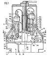
- Fig. 1
- einen vertikalen Schnitt durch eine erfindungsgemäße Werkzeugmaschine;
- Fig. 2
- einen Schnitt längs Linie 2-2 in Fig. 3 durch einen Maschinenständer der erfindungsgemäßen Werkzeugmaschine;
- Fig. 3
- eine Draufsicht von oben auf einen Maschinenständer der erfindungsgemäßen Werkzeugmaschine;
- Fig. 4
- eine Seitenansicht in Richtung des Pfeils A in Fig. 3;
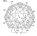
- Fig. 5
- einen Schnitt längs Linie 5-5 in Fig. 1 und
- Fig. 6
- einen Schnitt ähnlich Fig. 5 durch eine Variante des dargestellten Ausführungsbeispiels.
Claims (30)
- Werkzeugmaschine umfassend ein Maschinengestell mit einem Untergestell (14) und einem auf diesem sitzenden und einen Tragring aufweisenden Maschinenständer (40), einen um eine im wesentlichen vertikale Achse (20) drehbar am Tragring (19) gelagerten Träger, mehrere an dem Träger angeordnete Werkstückaufnahmeeinrichtungen (140) für zu bearbeitende Werkstücke (166), einen um die vertikale Achse herum verlaufenden Arbeitsraum (180), in welchem die Werkstückaufnahmeeinrichtungen (140) durch Drehen des Träger (96)um die vertikale Achse herum bewegbar sind, und eine Vielzahl von an dem Maschinengestell im Bereich des Arbeitsraums angeordneten Stationen (190), in welchen die Werkstückaufnahmeeinrichtungen während eines Bearbeitungszyklus positionierbar sind,
dadurch gekennzeichnet, daß der Maschinenständer (40) einen den Tragring (90) gegenüber dem Untergestell (14) fixierenden Versteifungsmantel (42) aufweist, welcher außerhalb des Arbeitsraums (180) verläuft und diesen zumindest teilweise umschließt, daß der Versteifungsmantel in einer um die vertikale Achse (20) herum verlaufende Mantelfläche (44) liegende und in dieser Mantelfläche (44) wirkende und vom Tragring (90) übertragene Kräfte (KV, Kq, KA) verformungssteif aufnehmende Manteltragwerkselemente (50) umfaßt, die miteinander zu einem verformungssteifen Mantelflächentragwerk (52) verbunden sind. - Werkzeugmaschine nach Anspruch 1, dadurch gekennzeichnet, daß der Versteifungsmantel (42) mehrere Durchbrüche (58) aufweist, über welche der Arbeitsraum (180) zugänglich ist.
- Werkzeugmaschine nach Anspruch 2, dadurch gekennzeichnet, daß der Arbeitsraum (180) ausschließlich über die Durchbrüche (58) im Versteifungsmantel (42) zugänglich ist.
- Werkzeugmaschine nach Anspruch 2 oder 3, dadurch gekennzeichnet, daß jeder Station (190) ein Durchbruch (58) im Versteifungsmantel (42) zugeordnet ist.
- Werkzeugmaschine nach Anspruch 3 oder 4, dadurch gekennzeichnet, daß die Stationen (190) Bearbeitungsstationen (190a bis f) umfassen und daß in jeder Bearbeitungsstation (190a bis f) der in dieser vorgesehene Werkzeugträger (26) über einen der Durchbrüche (58a bis f) von Außen zugänglich ist.
- Werkzeugmaschine nach Anspruch 5, dadurch gekennzeichnet, daß jeder Bearbeitungsstation (190a bis f) ein eigener Durchbruch (58a bis f) zugeordnet ist.
- Werkzeugmaschine nach einem der Ansprüche 3 bis 6, dadurch gekennzeichnet, daß die Stationen (190) eine Beund/oder Entladestation (190g,h) umfassen und daß in der Be- und/oder Entladestation (190g, h) eine Werkstücktransporteinrichtung (192, 194, 198) durch den Durchbruch (58g) hindurch verläuft.
- Werkzeugmaschine nach einem der Ansprüche 1 bis 7, dadurch gekennzeichnet, daß jedes der Manteltragwerkselemente (50) sich zumindest teilweise um einen der Durchbrüche (58) herum erstreckt.
- Werkzeugmaschine nach einem der Ansprüche 1 bis 8, dadurch gekennzeichnet, daß jedes Manteltragwerkselement (50) sich flächenhaft parallel zu der Mantelfläche erstreckende zusammenhängende Flachstreben (54, 60, 62, 64) umfaßt.
- Werkzeugmaschine nach Anspruch 9, dadurch gekennzeichnet, daß die Flachstreben (54, 60, 62, 64) innerhalb ihrer Außenkontur geschlossene Flächen aufweisen.
- Werkzeugmaschine nach Anspruch 9 oder 10, dadurch gekennzeichnet, daß die Flachstreben (54, 60, 62, 64) jedes Manteltragwerkselements (50) ein zusammenhängendes einstückiges Teil bilden.
- Werkzeugmaschine nach einem der Ansprüche 9 bis 11, dadurch gekennzeichnet, daß die Flachstreben (54, 60, 62, 64) jedes Manteltragwerkselements (50) einen den Durchbruch (58) umgebenden Rahmen bilden.
- Werkzeugmaschine nach einem der Ansprüche 1 bis 12, dadurch gekennzeichnet, daß zumindest ein Abschnitt (46) der Mantelfläche (44) zumindest über einen Teilumfang des Versteifungsmantels (42) ähnlich einem Bereich einer parallel zur vertikalen Achse prismatischen Fläche ausgebildet ist.
- Werkzeugmaschine nach einem der Ansprüche 1 bis 13, dadurch gekennzeichnet, daß zumindest ein Abschnitt (48) der Mantelfläche (44) zumindest über einen Teilumfang des Versteifungsmantels (42) ähnlich einem Bereich einer Kegelfläche mit einer parallel zur vertikalen Achse (20) verlaufenden Kegelachse ausgebildet ist.
- Werkzeugmaschine nach Anspruch 13 oder 14, dadurch gekennzeichnet, daß die Mantelfläche (44) eine vieleckige Grundfläche (701 bis 708) aufweist, die sich in von der Grundfläche weg verlaufenden Kanten (78) in die Mantelfläche (44) fortsetzt.
- Werkzeugmaschine nach Anspruch 15, dadurch gekennzeichnet, daß ein Teil der Grundfläche (701 bis 708) der Mantelfläche (44) die Form eines regelmäßigen Vielecks (701 bis 706) aufweist.
- Werkzeugmaschine nach Anspruch 15 oder 16, dadurch gekennzeichnet, daß sich jeweils ein Manteltragwerkselement (50) zwischen zwei in Umfangsrichtung aufeinanderfolgenden Ecken (741 bis 747) der vieleckigen Grundfläche erstreckt.
- Werkzeugmaschine nach einem der voranstehenden Ansprüche, dadurch gekennzeichnet, daß der Tragring (90) gegenüber dem Untergestell (14) durch Quertragwerkselemente (100) fixiert gehalten ist, welche sich in ungefähr parallel zur vertikalen Achse (20) und quer zur Mantelfläche (44) verlaufenden Querebenen (761 bis 767) erstrecken und in diesen Querebenen (761 bis 767) wirkende und vom Tragring (90) übertragene Kräfte (Kv) verformungssteif aufnehmen.
- Werkzeugmaschine nach Anspruch 18, dadurch gekennzeichnet, daß die Querebenen (761 bis 767) parallel zu radialen Richtungen zur vertikalen Achse (20) verlaufen.
- Werkzeugmaschine nach Anspruch 18 oder 19, dadurch gekennzeichnet, daß die Quertragwerkselemente (100) sich flächenhaft parallel zu den Querebenen (761 bis 767) erstrecken.
- Werkzeugmaschine nach Anspruch 20, dadurch gekennzeichnet, daß die Quertragwerkselemente als geschlossene Wandelemente (100) ausgebildet sind.
- Werkzeugmaschine nach einem der Ansprüche 18 bis 21, dadurch gekennzeichnet, daß die Quertragwerkselemente (100) einstückig mit dem Mantelflächentragwerk (52) verbunden sind.
- Werkzeugmaschine nach einem der Ansprüche 18 bis 22, dadurch gekennzeichnet, daß die Quertragwerkselemente (100) in Azimutalrichtung zur vertikalen Achse (20) jeweils zwischen zwei Stationen (190) angeordnet sind.
- Werkzeugmaschine nach Anspruch 23, dadurch gekennzeichnet, daß die Quertragwerkselemente (100) zwischen allen Bearbeitungsstationen (190a bis f) angeordnet sind.
- Werkzeugmaschine nach einem der Ansprüche 18 bis 24, dadurch gekennzeichnet, daß die Quertragwerkselemente (100) innerhalb des Mantelflächentragwerks (52) angeordnet sind.
- Werkzeugmaschine nach einem der voranstehenden Ansprüche, dadurch gekennzeichnet, daß das Mantelflächentragwerk (52) mit sich zumindest teilweise in azimutaler Richtung erstreckenden Versteifungsstreben (108, 110) versehen ist.
- Werkzeugmaschine nach Anspruch 26, dadurch gekennzeichnet, daß die Versteifungsstreben (108, 110) in einer quer zur vertikalen Achse (20) verlaufenden Ebene (38, 112) liegen.
- Werkzeugmaschine nach Anspruch 26 oder 27, dadurch gekennzeichnet, daß sich die Versteifungsstreben (108, 110) jeweils bis zu den Quertragwerkselementen (100) erstrecken und mit diesen verbunden sind.
- Werkzeugmaschine nach einem der Ansprüche 26 bis 28, dadurch gekennzeichnet, daß die Versteifungsstreben (108, 110) einstückig mit dem Mantelflächentragwerk (52) verbunden sind.
- Werkzeugmaschine nach einem der voranstehenden Ansprüche, dadurch gekennzeichnet, daß der Maschinenständer (40) so dimensioniert ist, daß er hinsichtlich seiner Steifigkeit eine mehrzählige Symmetrie zur vertikalen Achse (20) aufweist.
Applications Claiming Priority (2)
| Application Number | Priority Date | Filing Date | Title |
|---|---|---|---|
| DE19841449 | 1998-09-10 | ||
| DE19841449A DE19841449A1 (de) | 1998-09-10 | 1998-09-10 | Werkzeugmaschine |
Publications (3)
| Publication Number | Publication Date |
|---|---|
| EP0985487A2 EP0985487A2 (de) | 2000-03-15 |
| EP0985487A3 EP0985487A3 (de) | 2001-06-06 |
| EP0985487B1 true EP0985487B1 (de) | 2004-04-07 |
Family
ID=7880540
Family Applications (1)
| Application Number | Title | Priority Date | Filing Date |
|---|---|---|---|
| EP99116152A Expired - Lifetime EP0985487B1 (de) | 1998-09-10 | 1999-08-19 | Werkzeugmaschine |
Country Status (3)
| Country | Link |
|---|---|
| US (1) | US6085622A (de) |
| EP (1) | EP0985487B1 (de) |
| DE (2) | DE19841449A1 (de) |
Families Citing this family (7)
| Publication number | Priority date | Publication date | Assignee | Title |
|---|---|---|---|---|
| DE19916212C2 (de) * | 1999-04-10 | 2003-07-10 | Schuette Alfred H Gmbh & Co Kg | Mehrspindelige Werkzeugmaschine, insbesondere Mehrspindeldrehautomat |
| EP1106304B1 (de) * | 1999-12-01 | 2006-03-08 | Index-Werke Gmbh & Co. Kg Hahn & Tessky | Werkzeugmaschine |
| DE19959961A1 (de) * | 1999-12-13 | 2001-06-28 | Index Werke Kg Hahn & Tessky | Drehmaschine |
| DE10153807A1 (de) * | 2001-11-05 | 2003-05-28 | Emag Maschfab Gmbh | Werkzeugmaschine |
| DE102009013067A1 (de) | 2009-03-16 | 2010-10-07 | Mag Europe Gmbh | Werkzeugmaschine und Verfahren zur Bearbeitung von Werkstücken |
| IT1399706B1 (it) * | 2010-04-09 | 2013-04-26 | Danieli Off Mecc | Macchina per la filettatura di manicotti o simili, e relativo procedimento |
| DE102017127116B4 (de) | 2017-11-17 | 2019-07-11 | Scherer-Feinbau Gmbh | Werkzeugmaschine, Fertigungszelle sowie Verfahren zum Betreiben einer Fertigungszelle |
Family Cites Families (5)
| Publication number | Priority date | Publication date | Assignee | Title |
|---|---|---|---|---|
| US2635325A (en) * | 1948-01-12 | 1953-04-21 | Rheem Mfg Co | Vertical automatic machine tool |
| US3260140A (en) * | 1963-11-26 | 1966-07-12 | William G Burge | Vertical boring mills |
| DE2755755C2 (de) * | 1977-12-14 | 1983-09-29 | Witzig & Frank Maschinenbaugesellschaft mbH, 7031 Gärtingen | Rundtakt-Werkzeugmaschine |
| DE19504369A1 (de) * | 1995-02-10 | 1996-08-14 | Index Werke Kg Hahn & Tessky | Mehrspindelwerkzeugmaschine |
| DE19601433C2 (de) * | 1996-01-17 | 1999-05-12 | Witzig & Frank Turmatic Gmbh | Mehrstationen-Werkzeugmaschine |
-
1998
- 1998-09-10 DE DE19841449A patent/DE19841449A1/de not_active Ceased
- 1998-11-20 US US09/196,708 patent/US6085622A/en not_active Expired - Lifetime
-
1999
- 1999-08-19 DE DE59909094T patent/DE59909094D1/de not_active Expired - Fee Related
- 1999-08-19 EP EP99116152A patent/EP0985487B1/de not_active Expired - Lifetime
Also Published As
| Publication number | Publication date |
|---|---|
| DE19841449A1 (de) | 2000-03-23 |
| US6085622A (en) | 2000-07-11 |
| DE59909094D1 (de) | 2004-05-13 |
| EP0985487A2 (de) | 2000-03-15 |
| EP0985487A3 (de) | 2001-06-06 |
Similar Documents
| Publication | Publication Date | Title |
|---|---|---|
| EP1180413B1 (de) | Mehrspindelwerkzeugmaschine | |
| DE4301393C2 (de) | Rundtakt-Werkzeugmaschine | |
| EP1064119B1 (de) | Rundtaktmaschine | |
| EP1886762B1 (de) | Werkzeugmaschine | |
| EP1886763B1 (de) | Werkzeugmagazin für eine Werkzeugmaschine | |
| EP1886764B1 (de) | Werkzeugmaschine | |
| EP1722921B1 (de) | Werkzeugmaschine mit einem umrüstbaren werkstückspanntisch | |
| WO1993007981A1 (de) | Drehmaschine | |
| DE19504368A1 (de) | Werkzeugmaschine | |
| DE102004031066A1 (de) | Werkzeugmaschine mit mindestens einer Arbeitsspindel | |
| EP0885686A1 (de) | Bearbeitungszelle | |
| DE10116994A1 (de) | Werkzeugmaschine | |
| EP1058593A1 (de) | Hexapod-bearbeitungszentrum | |
| EP1927429A1 (de) | Werkzeugmaschine mit Werkzeugmagazin | |
| EP2123379B1 (de) | Fräs- und Drehmaschine | |
| EP2021149A1 (de) | Werkzeugmaschine | |
| EP0985487A2 (de) | Werkzeugmaschine | |
| EP1454711A1 (de) | Mehrspindeldrehmaschine mit Schwenkarmhandhabungseinrichtung | |
| DE10213778A1 (de) | Werkzeugmaschine | |
| DE3236356A1 (de) | Bearbeitungszentrum | |
| EP1106304A1 (de) | Werkzeugmaschine | |
| EP0331178A1 (de) | Kompaktaufbau einer Säulenbohrmaschine | |
| DE4031997A1 (de) | Werkzeugmaschine | |
| DE19938058B4 (de) | Bewegungseinrichtung zur Bewegung einer Halteeinrichtung | |
| EP1862256B1 (de) | Drehbearbeitungszentrum |
Legal Events
| Date | Code | Title | Description |
|---|---|---|---|
| PUAI | Public reference made under article 153(3) epc to a published international application that has entered the european phase |
Free format text: ORIGINAL CODE: 0009012 |
|
| AK | Designated contracting states |
Kind code of ref document: A2 Designated state(s): CH DE ES FR IT LI |
|
| AX | Request for extension of the european patent |
Free format text: AL;LT;LV;MK;RO;SI |
|
| PUAL | Search report despatched |
Free format text: ORIGINAL CODE: 0009013 |
|
| AK | Designated contracting states |
Kind code of ref document: A3 Designated state(s): AT BE CH CY DE DK ES FI FR GB GR IE IT LI LU MC NL PT SE |
|
| AX | Request for extension of the european patent |
Free format text: AL;LT;LV;MK;RO;SI |
|
| 17P | Request for examination filed |
Effective date: 20011203 |
|
| AKX | Designation fees paid |
Free format text: CH DE ES FR IT LI |
|
| GRAP | Despatch of communication of intention to grant a patent |
Free format text: ORIGINAL CODE: EPIDOSNIGR1 |
|
| GRAS | Grant fee paid |
Free format text: ORIGINAL CODE: EPIDOSNIGR3 |
|
| GRAA | (expected) grant |
Free format text: ORIGINAL CODE: 0009210 |
|
| AK | Designated contracting states |
Kind code of ref document: B1 Designated state(s): CH DE ES FR IT LI |
|
| PG25 | Lapsed in a contracting state [announced via postgrant information from national office to epo] |
Ref country code: FR Free format text: LAPSE BECAUSE OF FAILURE TO SUBMIT A TRANSLATION OF THE DESCRIPTION OR TO PAY THE FEE WITHIN THE PRESCRIBED TIME-LIMIT Effective date: 20040407 |
|
| REG | Reference to a national code |
Ref country code: CH Ref legal event code: EP |
|
| REF | Corresponds to: |
Ref document number: 59909094 Country of ref document: DE Date of ref document: 20040513 Kind code of ref document: P |
|
| REG | Reference to a national code |
Ref country code: CH Ref legal event code: NV Representative=s name: KIRKER & CIE SA |
|
| PG25 | Lapsed in a contracting state [announced via postgrant information from national office to epo] |
Ref country code: ES Free format text: LAPSE BECAUSE OF FAILURE TO SUBMIT A TRANSLATION OF THE DESCRIPTION OR TO PAY THE FEE WITHIN THE PRESCRIBED TIME-LIMIT Effective date: 20040718 |
|
| PLBE | No opposition filed within time limit |
Free format text: ORIGINAL CODE: 0009261 |
|
| STAA | Information on the status of an ep patent application or granted ep patent |
Free format text: STATUS: NO OPPOSITION FILED WITHIN TIME LIMIT |
|
| EN | Fr: translation not filed | ||
| 26N | No opposition filed |
Effective date: 20050110 |
|
| PGFP | Annual fee paid to national office [announced via postgrant information from national office to epo] |
Ref country code: CH Payment date: 20080826 Year of fee payment: 10 |
|
| PGFP | Annual fee paid to national office [announced via postgrant information from national office to epo] |
Ref country code: DE Payment date: 20080929 Year of fee payment: 10 |
|
| PG25 | Lapsed in a contracting state [announced via postgrant information from national office to epo] |
Ref country code: IT Free format text: LAPSE BECAUSE OF NON-PAYMENT OF DUE FEES Effective date: 20070819 |
|
| REG | Reference to a national code |
Ref country code: CH Ref legal event code: PL |
|
| PG25 | Lapsed in a contracting state [announced via postgrant information from national office to epo] |
Ref country code: LI Free format text: LAPSE BECAUSE OF NON-PAYMENT OF DUE FEES Effective date: 20090831 Ref country code: CH Free format text: LAPSE BECAUSE OF NON-PAYMENT OF DUE FEES Effective date: 20090831 |
|
| PG25 | Lapsed in a contracting state [announced via postgrant information from national office to epo] |
Ref country code: DE Free format text: LAPSE BECAUSE OF NON-PAYMENT OF DUE FEES Effective date: 20100302 |
|
| PGFP | Annual fee paid to national office [announced via postgrant information from national office to epo] |
Ref country code: IT Payment date: 20080819 Year of fee payment: 10 |
|
| PGRI | Patent reinstated in contracting state [announced from national office to epo] |
Ref country code: IT Effective date: 20110616 |
|
| PGRI | Patent reinstated in contracting state [announced from national office to epo] |
Ref country code: IT Effective date: 20110616 |