EP0984120A1 - Connection assembly - Google Patents
Connection assembly Download PDFInfo
- Publication number
- EP0984120A1 EP0984120A1 EP99116578A EP99116578A EP0984120A1 EP 0984120 A1 EP0984120 A1 EP 0984120A1 EP 99116578 A EP99116578 A EP 99116578A EP 99116578 A EP99116578 A EP 99116578A EP 0984120 A1 EP0984120 A1 EP 0984120A1
- Authority
- EP
- European Patent Office
- Prior art keywords
- plastic
- cap
- connecting part
- base body
- metal base
- Prior art date
- Legal status (The legal status is an assumption and is not a legal conclusion. Google has not performed a legal analysis and makes no representation as to the accuracy of the status listed.)
- Granted
Links
Images


Classifications
-
- E—FIXED CONSTRUCTIONS
- E05—LOCKS; KEYS; WINDOW OR DOOR FITTINGS; SAFES
- E05B—LOCKS; ACCESSORIES THEREFOR; HANDCUFFS
- E05B15/00—Other details of locks; Parts for engagement by bolts of fastening devices
- E05B15/02—Striking-plates; Keepers; Bolt staples; Escutcheons
Definitions
- the invention relates to a connection arrangement with a metal base body and a cap for covering the metal base body.
- connection arrangements are used in building fittings as well as in the sanitary area.
- the metal base body can have a mounting surface, for example a door, to be connected there as Basis for further superstructures or attachments or as a functional element serve.
- the cap To connect the cap to the metal body the cap usually has several locking projections in undercuts engage the metal body.
- the plastic cap is formed (plastic cap), and that the connection arrangement has a plastic connecting part on the metal base body is attachable and on which the plastic cap to form a Plastic-plastic contact can be locked.
- a plastic connecting part is therefore provided, with which can also be connected to the plastic cap.
- Possible deformations caused by environmental influences thus have an effect of plastics, especially expansions of polyamides, in in essentially the same way on both the cap and the Connection part from, so that the stability of this connection even in If the plastics used are susceptible to deformation does not deteriorate significantly in the long run.
- the plastic connecting part can be a Functional element act when using the connection arrangement fulfills other tasks as building hardware or as a sanitary element.
- the cap and the connecting part can have locking projections and corresponding undercuts be provided on the cap and the connecting part.
- the undercut on the plastic connecting part or on the Plastic cap designed as a spring-back undercut. This ensures the stability of the connection between the cap and the connecting part increased even further because, on the one hand, a higher original engagement pressure between the locking projection and the spring undercut can be provided, and because the spring travel of the spring undercut Deformation of the plastic cap and the plastic connecting part to compensate for each other to an even greater extent can
- the spring undercut can be used as an undercut on a longitudinal extension be formed by the plastic connecting part or of the plastic cap across, especially at right angles to that direction extends along which the locking projection into the undercut formed should grip (direction of engagement). It is preferred if the The longitudinal direction of this longitudinal process is also transverse, in particular extends perpendicular to the direction along which the plastic cap to cover the base body including the connecting part to be placed on the plastic connector (direction of attachment). In this way, the one that forms the spring undercut Longitudinal process within the main extension plane of the connecting part run so that the plastic connecting part with a shallow depth and can be manufactured in a particularly simple manner.
- the design of the undercut can also be that of the snap connection provided between the plastic cap and the plastic connecting part Snap projection be designed to be resilient.
- plastics with different relative to each other Deformation susceptibility can be used. In doing so, extent and direction of the expected deformation are taken into account. Inexpensive plastics can be used at least in part, for which a comparatively high susceptibility to deformation is accepted can be.
- the plastic connecting part and the plastic cap can be the connecting part for immediate snap connection with the cap between the cap and be arranged the base body, or the base body is between the connecting part and the cap arranged, at least the undercuts or locking projections of the connecting part protrude the base body to the snap connection with the cap enable.
- the object of the invention is for a connection arrangement of the entry mentioned type to the other solved in that the cap Metal is formed (metal cap) that the connection arrangement Has plastic connecting part that can be attached to the metal base body and at least one resilient undercut (Spring undercut), and that the metal cap at least has a locking projection assigned to the spring undercut, through which the metal cap with the plastic connector can be locked.
- the cap Metal is formed (metal cap) that the connection arrangement Has plastic connecting part that can be attached to the metal base body and at least one resilient undercut (Spring undercut), and that the metal cap at least has a locking projection assigned to the spring undercut, through which the metal cap with the plastic connector can be locked.
- a metal cap is therefore provided is not directly connected to the metal base body, but with a connecting part fastened to the metal base body Plastic, for example made of a polyamide, is locked.
- the plastic connecting part has one or more spring undercuts, and the metal cap has corresponding locking projections.
- the undercut formed can also be the one formed from metal Cap with the arrangement of metal body and plastic connecting part be snapped to cover this arrangement. Any subsequent deformation of the plastic connector can by the springback effect of the spring undercut be compensated for, so that a reliable seat of the Metal cap is guaranteed.
- the features of the embodiment with a plastic cap transferable accordingly are the features of the embodiment with a plastic cap transferable accordingly.
- the spring undercut on a cross to the direction of engagement and / or Longitudinal extension of the plastic connecting part in the direction of attachment be formed, and the connecting part can with respect to the metal cap be arranged in front of or behind the metal body.
- the above designations of the viewing directions refer to on the arrangement of the parts of the connection arrangement shown in the assembled state shown in Fig. 4 on a mounting surface.
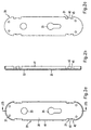
- FIG. 1a-1c show a plastic connecting part 11 of a connecting arrangement, the as a fitting on a door to hold a door handle as well as a locking cylinder.
- the plastic connector 11 has four recessed locking areas 15 with rectangular recesses on a rear side 13 17. At each rest area 15 there is one Rectangular recess 17 integrally formed longitudinal extension 19. The outside of each longitudinal extension 19 extends parallel to the corresponding narrow side of the plastic connecting part 11 A front 21 of the plastic connecting part 11 is each longitudinal extension 19 bevelled towards its outside.
- the plastic connector 11 also has a pusher opening 23, a Lock opening 25 and four fastening openings 27.
- FIGS. 2a-2c show an assigned to the plastic connecting part 11 Metal base body 29. This has four rectangular recesses 31, a handle opening 33, a lock opening 35 and four fastening openings 37, the location and extent of the recesses 17th or openings 23, 25, 27 of the plastic connecting part 11 correspond.
- the metal base body 29 has a rear 39 Fold 41.
- the fold 41 is interrupted at the rectangular recesses 31, and there are at right angles to the metal body 29 locking tabs 43.
- the locking tabs 43 are with respect to the fold 41 set back and have one at each of their two longitudinal ends Detent tooth 45.
- 3a to 3c show an associated cap 47.
- This has a circumferential one Edge area 49, which is perpendicular to the main direction of extension the cap 47 and on the inside - according to the arrangement of the longitudinal extensions 19 on the plastic connecting part 11 - four latching projections 51 with a nose-shaped cross section are arranged (see also Fig. 4).
- the cap 47 has one of the pusher openings 23, 33 and lock openings 25, 35 of the plastic connecting part 11 or the metal base body 29 corresponding pusher opening 53 and Lock opening 55 on.
- the assembly of the plastic connecting part 11, the metal base body 29 and the cap 47 is carried out in the following way: First, for the purpose of pre-assembly, the plastic connecting part 11 on the Metal base body 29 fastened by the plastic connecting part 11 with its front 21 in the fold 41 on the back 39 of the metal base body 29 is used.
- the latching tabs 43 engage behind with their locking teeth 45, the rectangular recesses 17 on their transverse edges.
- the plastic connecting part 11 and the metal base body 29 also via the fastening openings 27, 37 or other fastening openings as well as corresponding fastening elements be attached to each other.
- the metal base body 29 can be attached in this way be attached to a door that the fold 41 with its narrow side on the Door abuts and the plastic connecting part 11 between the door, the Metal base body 29 and the fold 41 is caught.
- the basic body 29 can, for example, via the fastening openings 37 with the door be screwed.
- the cap 47 can be opened the metal base body 29 or from the rectangular recesses 31 of the metal base body 29 protruding longitudinal extensions 19 of the Plastic connector 11 are placed. Thereby lie first the locking projections 51 of the cap 47 on the bevels of the longitudinal processes 19 on. With further touchdown movement the longitudinal processes 19 pushed back into the respective rectangular recess 17, and the Locking projections 51 can be made along the outside of the longitudinal extensions 19 up to the level of the locking areas 15 on the rear 13 of the plastic connecting part 11 slide. There snap-in projections 51 snap on the likewise recessed rear side 13 of the longitudinal processes 19.
- the longitudinal extensions 19 thus form undercuts for the locking projections 51 of the cap 47, the longitudinal extensions 19 with respect to the direction of engagement, in which the locking projections 51 ultimately the longitudinal extensions 19 cover, are designed to spring back.
- the rectangular recesses 17 on the plastic connecting part 11 are therefore not only used for receiving the locking tabs 43 of the metal base body 29, but also as Spring back area for the longitudinal processes 19.
- the deepened formation of the Latching areas 15, in particular the longitudinal extensions 19, enable a snapping in the locking projections 51 of the cap 47 also in such cases where the plastic connector 11 on the mounting surface in question is present.
- Fig. 4 shows the so attached to a mounting surface 57 Connection arrangement in a cross section along the planes IV-IV, which are shown in Fig. 1c for the plastic connecting part 11 and accordingly chosen for the metal base body 29 and the cap 47 are. 4, the cap 47 is in one Setting direction 59 on the metal base body 29 together with the plastic connecting part 11 placed, and engage behind the locking projections 51 the longitudinal extensions 19 each in an engagement direction 61.
- the internal dimensions of the on the mounting surface 57 adjacent fold 41 of the metal base body 29 slightly larger are selected as the dimensions of the outline of the plastic connecting part 11. Stand only at the rectangular recesses 31 the longitudinal extensions 19 of the plastic connecting part serving as spring undercuts 11 over the fold 41 of the metal base body 29 about.
- the internal dimensions of the edge region 49 of the cap 47 correspond to the External dimensions of the longitudinal extensions 19 in their relaxed state.
- the Depth of the cap edge region 49 is selected so that when on the metal base body 29 adjacent cap 47 whose edge region 49 on the fastening surface 57 rests and the locking projections 51 secure the longitudinal extensions 19 reach behind.
- the fold 41 and the locking tab 43 of the metal base body 29 and the rear 13 of the plastic connecting part 11 are also on the mounting surface 57.
- the cap 47 can - like the plastic connecting part - made of plastic be made.
- the locking projections 51 of the cap 47 to an increasing extent out of engagement with the longitudinal processes 19 reach if the cap 47 is due to moisture absorption extends along the sectional plane shown in Fig. 4.
- this will Effect compensated by the fact that the plastic connecting part 11 with its longitudinal extensions 19 is made of plastic and, if necessary expands in the appropriate directions.
- the cap 47 can also be made of metal.
- the cap 47 In this Fall can be the resilient configuration of the 19 formed by the longitudinal processes Undercuts for making the snap connection required inherent elasticity of the locking projections 51 of the metal cap 47 compensate. Expansion due to moisture absorption of the plastic connecting part 11 is transferred to the longitudinal processes 19 and reinforces the locking connection received with the locking projections 51.
- the locking connection between the locking tabs 43 of the metal base body 29 and the rectangular recesses 17 of the plastic connecting part 11, on the other hand, is not critical to a possible deformation of the plastic connecting part 11, since this latching connection is simply loved the pre-assembly of plastic connector 11 and metal base 29 serves together.
- FIGS. 5a to 5c and 6a and 6b An alternative possibility for this locking connection is in FIGS. 5a to 5c and 6a and 6b for a further metal base body 29 'and a another plastic connecting part 11 'shown.
- the further metal base body 29 ' has a circumferential fold 41 Rectangular recesses 31 (see FIG. 5b). Adjacent to each rectangular recess 31 protrudes from the inner peripheral surface of the fold 41 Latch 65 in the direction of the longitudinal center axis of the further metal base body 29 '.
- the further metal base body 29 ' is attached attached to the further plastic connecting part 11 'by such the plastic connecting part 11 'is placed, which the locking lugs 65th engage behind the locking undercuts 63 or the locking undercuts 63 spring back to the catches 65.
- the plastic connecting part 11 out of less to produce plastic that is susceptible to deformation, e.g. from PA12, while a comparatively for the production of the cap 47 made of plastic inexpensive plastic, for example PA6, can be selected can.
Landscapes
- Connection Of Plates (AREA)
- Building Environments (AREA)
- Coupling Device And Connection With Printed Circuit (AREA)
- Monitoring And Testing Of Exchanges (AREA)
- Manufacturing Of Electric Cables (AREA)
- Road Paving Structures (AREA)
- Steam Or Hot-Water Central Heating Systems (AREA)
- Residential Or Office Buildings (AREA)
- Non-Disconnectible Joints And Screw-Threaded Joints (AREA)
Abstract
Description
Die Erfindung betrifft eine Verbindungsanordnung mit einem Metall-Grundkörper und einer Kappe zur Bedeckung des Metall-Grundkörpers.The invention relates to a connection arrangement with a metal base body and a cap for covering the metal base body.
Derartige Verbindungsanordnungen finden Verwendung bei Baubeschlägen sowie im Sanitärbereich. Der Metall-Grundkörper kann mit einer Befestigungsfläche, beispielsweise einer Tür, verbunden sein, um dort als Basis für weitere Aufbauten oder Anbauten oder als Funktionselement zu dienen. Zur Verbindung der Kappe mit dem Metall-Grundkörper besitzt die Kappe üblicherweise mehrere Rastvorsprünge, die in Hinterschneidungen an dem Metall-Grundkörper eingreifen.Such connection arrangements are used in building fittings as well as in the sanitary area. The metal base body can have a mounting surface, for example a door, to be connected there as Basis for further superstructures or attachments or as a functional element serve. To connect the cap to the metal body the cap usually has several locking projections in undercuts engage the metal body.
Es ist ein Nachteil der bekannten Verbindungsanordnungen, daß die Kappe nicht ohne weiteres aus einem kostengünstigen Kunststoff, wie z. B. Polyamid-6 (PA6), hergestellt werden kann. Derartige Kunststoffe unterliegen nämlich einer gewissen Verformungsanfälligkeit. Beispielsweise nimmt PA6 Feuchtigkeit aus der Luft auf und dehnt sich dabei aus. Dadurch kann die Eingriffsverbindung einer Kunststoff-Kappe mit dem Metall-Grundkörper ihre Wirkung verlieren, so daß die Kappe von dem Grundkörper abfällt. Eine Rastverbindung einer Metall-Kappe mit dem Metall-Grundkörper ist aufgrund der geringen Elastität der beiden Metallteile nicht möglich.It is a disadvantage of the known connection arrangements that the cap not easily from an inexpensive plastic, such as. B. Polyamide-6 (PA6) can be produced. Such plastics are subject namely a certain susceptibility to deformation. For example PA6 absorbs moisture from the air and expands in the process. Thereby can the engagement connection of a plastic cap with the metal base body lose their effect, so that the cap of the Basic body falls off. A snap connection of a metal cap with the Metal body is due to the low elasticity of the two metal parts not possible.
Es ist eine Aufgabe der Erfindung, eine Verbindungsanordnung mit einem Metall-Grundkörper und einer Kappe zu schaffen, bei der der Metall-Grundkörper auf dauerhaft zuverlässige Weise und ohne von außen an der Kappe erkennbare Befestigungselemente mit der Kappe bedeckt werden kann.It is an object of the invention to provide a connection arrangement with a Metal base body and a cap to create the metal base body in a permanently reliable way and without outside fastening elements recognizable in the cap are covered with the cap can.
Diese Aufgabe wird zum einen dadurch gelöst, daß die Kappe aus Kunststoff gebildet ist (Kunststoff-Kappe), und daß die Verbindungsanordnung ein Kunststoff-Verbindungsteil aufweist, das an dem Metall-Grundkörper befestigbar ist und an dem die Kunststoff-Kappe unter Ausbildung eines Kunststoff-Kunststoff-Kontakts verrastbar ist.This object is achieved on the one hand in that the plastic cap is formed (plastic cap), and that the connection arrangement has a plastic connecting part on the metal base body is attachable and on which the plastic cap to form a Plastic-plastic contact can be locked.
Erfindungsgemäß ist also ein Kunststoff-Verbindungsteil vorgesehen, mit dem die ebenfalls aus Kunststoff gebildete Kappe verbunden werden kann. Somit wirken sich eventuelle durch Umgebungseinflüsse bedingte Verformungen der Kunststoffe, insbesondere Ausdehnungen von Polyamiden, in im wesentlichen gleicher Weise sowohl auf die Kappe als auch auf das Verbindungsteil aus, so daß die Stabilität dieser Verbindung selbst im Falle einer gewissen Verformungsanfälligkeit der verwendeten Kunststoffe sich auch auf Dauer nicht wesentlich verschlechtert.According to the invention, a plastic connecting part is therefore provided, with which can also be connected to the plastic cap. Possible deformations caused by environmental influences thus have an effect of plastics, especially expansions of polyamides, in in essentially the same way on both the cap and the Connection part from, so that the stability of this connection even in If the plastics used are susceptible to deformation does not deteriorate significantly in the long run.
Da die Kunststoff-Kappe sowohl den Metall-Grundkörper als auch das daran befestigte Kunststoff-Verbindungsteil bedeckt, kann die Befestigung des Verbindungsteils an dem Grundkörper auf beliebige bekannte Weise erfolgen, also auch mittels zusätzlicher Befestigungselemente, die nach Bedeckung mit der Kappe von außen nicht mehr erkennbar sind.Since the plastic cap both the metal body and that attached plastic connector covered, the attachment of the connecting part on the base body in any known manner take place, so also by means of additional fasteners that after Covering with the cap is no longer recognizable from the outside.
Bei dem Kunststoff-Verbindungsteil kann es sich gleichzeitig um ein Funktionselement handeln, das bei der Verwendung der Verbindungsanordnung als Baubeschlag oder als Sanitärelement weitere Aufgaben erfüllt. The plastic connecting part can be a Functional element act when using the connection arrangement fulfills other tasks as building hardware or as a sanitary element.
Zur Herstellung der Rastverbindung zwischen der Kappe und dem Verbindungsteil können Rastvorsprünge und entsprechende Hinterschneidungen an der Kappe und dem Verbindungsteil vorgesehen sein. Vorzugsweise ist die Hinterschneidung an dem Kunststoff-Verbindungsteil bzw. an der Kunststoff-Kappe als rückfedernde Federhinterschneidung ausgestaltet. Dadurch wird die Stabilität der Verbindung von Kappe und Verbindungsteil noch weiter erhöht, da zum einen ein höherer ursprünglicher Eingriffsdruck zwischen dem Rastvorsprung und der Federhinterschneidung vorgesehen werden kann, und da zum anderen der Federweg der Federhinterschneidung Verformungen der Kunststoff-Kappe und des Kunststoff-Verbindungsteils relativ zueinander in noch stärkerem Ausmaß auszugleichen vermag.To make the snap connection between the cap and the connecting part can have locking projections and corresponding undercuts be provided on the cap and the connecting part. Preferably the undercut on the plastic connecting part or on the Plastic cap designed as a spring-back undercut. This ensures the stability of the connection between the cap and the connecting part increased even further because, on the one hand, a higher original engagement pressure between the locking projection and the spring undercut can be provided, and because the spring travel of the spring undercut Deformation of the plastic cap and the plastic connecting part to compensate for each other to an even greater extent can
Die Federhinterschneidung kann als Hinterschneidung an einem Längsfortsatz gebildet sein, der sich von dem Kunststoff-Verbindungsteil bzw. von der Kunststoff-Kappe quer, insbesondere rechtwinklig zu jener Richtung erstreckt, entlang welcher der Rastvorsprung in die gebildete Hinterschneidung greifen soll (Eingriffsrichtung). Es ist bevorzugt, wenn die Längsrichtung dieses Längsfortsatzes sich außerdem quer, insbesondere rechtwinklig zu jener Richtung erstreckt, entlang welcher die Kunststoff-Kappe zum Bedecken des Grundkörpers einschließlich des Verbindungsteils auf das Kunststoff-Verbindungsteil aufgesetzt werden soll (Aufsetzrichtung). Auf diese Weise kann der die Federhinterschneidung bildende Längsfortsatz innerhalb der Haupterstreckungsebene des Verbindungsteils verlaufen, so daß das Kunststoff-Verbindungsteil mit geringer Bautiefe und auf besonders einfache Weise hergestellt werden kann. The spring undercut can be used as an undercut on a longitudinal extension be formed by the plastic connecting part or of the plastic cap across, especially at right angles to that direction extends along which the locking projection into the undercut formed should grip (direction of engagement). It is preferred if the The longitudinal direction of this longitudinal process is also transverse, in particular extends perpendicular to the direction along which the plastic cap to cover the base body including the connecting part to be placed on the plastic connector (direction of attachment). In this way, the one that forms the spring undercut Longitudinal process within the main extension plane of the connecting part run so that the plastic connecting part with a shallow depth and can be manufactured in a particularly simple manner.
Zusätzlich oder alternativ zu der vorstehend erläuterten rückfedernden Ausgestaltung der Hinterschneidung kann auch der für die Rastverbindung zwischen Kunststoff-Kappe und Kunststoff-Verbindungsteil vorgesehene Rastvorsprung rückfedernd ausgestaltet sein.In addition or as an alternative to the springback described above The design of the undercut can also be that of the snap connection provided between the plastic cap and the plastic connecting part Snap projection be designed to be resilient.
Für die Herstellung der Kunststoff-Kappe und des Kunststoff-Verbindungsteils können gezielt Kunststoffe mit relativ zueinander unterschiedlicher Verformungsanfälligkeit verwendet werden. Dabei können Ausmaß und Richtung der zu erwartenden Verformung berücksichtigt werden. Zumindest teilweise können kostengünstige Kunststoffe eingesetzt werden, für die eine vergleichsweise hohe Verformungsanfälligkeit in Kauf genommen werden kann.For the production of the plastic cap and the plastic connecting part can target plastics with different relative to each other Deformation susceptibility can be used. In doing so, extent and direction of the expected deformation are taken into account. Inexpensive plastics can be used at least in part, for which a comparatively high susceptibility to deformation is accepted can be.
Bei einer flächigen Ausbildung des Metall-Grundkörpers, des Kunststoff-Verbindungsteils und der Kunststoff-Kappe kann das Verbindungsteil zur unmittelbaren Rastverbindung mit der Kappe zwischen der Kappe und dem Grundkörper angeordnet werden, oder der Grundkörper wird zwischen dem Verbindungsteil und der Kappe angeordnet, wobei zumindest die Hinterschneidungen bzw. Rastvorsprünge des Verbindungsteils über den Grundkörper überstehen, um die Rastverbindung mit der Kappe zu ermöglichen.With a flat design of the metal base body, the plastic connecting part and the plastic cap can be the connecting part for immediate snap connection with the cap between the cap and be arranged the base body, or the base body is between the connecting part and the cap arranged, at least the undercuts or locking projections of the connecting part protrude the base body to the snap connection with the cap enable.
Die Aufgabe der Erfindung wird für eine Verbindungsanordnung der eingangs genannten Art zum anderen dadurch gelöst, daß die Kappe aus Metall gebildet ist (Metall-Kappe), daß die Verbindungsanordnung ein Kunststoff-Verbindungsteil aufweist, das an dem Metall-Grundkörper befestigbar ist und wenigstens eine rückfedernd ausgebildete Hinterschneidung (Federhinterschneidung) aufweist, und daß die Metall-Kappe wenigstens einen der Federhinterschneidung zugeordneten Rastvorsprung aufweist, durch den die Metall-Kappe mit dem Kunststoff-Verbindungsteil verrastbar ist.The object of the invention is for a connection arrangement of the entry mentioned type to the other solved in that the cap Metal is formed (metal cap) that the connection arrangement Has plastic connecting part that can be attached to the metal base body and at least one resilient undercut (Spring undercut), and that the metal cap at least has a locking projection assigned to the spring undercut, through which the metal cap with the plastic connector can be locked.
Bei dieser Ausführungsform ist also eine Metall-Kappe vorgesehen, die nicht unmittelbar mit dem Metall-Grundkörper verbunden wird, sondern mit einem an dem Metall-Grundkörper befestigten Verbindungsteil aus Kunststoff, beispielsweise aus einem Polyamid, verrastet wird. Hierfür besitzt das Kunststoff-Verbindungsteil eine oder mehrere Federhinterschneidungen, und die Metall-Kappe weist entsprechende Rastvorsprünge auf.In this embodiment, a metal cap is therefore provided is not directly connected to the metal base body, but with a connecting part fastened to the metal base body Plastic, for example made of a polyamide, is locked. For that owns the plastic connecting part has one or more spring undercuts, and the metal cap has corresponding locking projections.
Aufgrund der rückfedernden Ausbildung der an dem Kunststoff-Verbindungsteil gebildeten Hinterschneidung kann also auch die aus Metall gebildete Kappe mit der Anordnung aus Metall-Grundkörper und Kunststoff-Verbindungsteil verrastet werden, um diese Anordnung zu bedecken. Eventuelle nachträgliche Verformungen des Kunststoff-Verbindungsteils können durch die rückfedernde Wirkung der Federhinterschneidung kompensiert werden, so daß auch langfristig ein zuverlässiger Sitz der Metall-Kappe gewährleistet ist.Due to the resilient design of the plastic connecting part The undercut formed can also be the one formed from metal Cap with the arrangement of metal body and plastic connecting part be snapped to cover this arrangement. Any subsequent deformation of the plastic connector can by the springback effect of the spring undercut be compensated for, so that a reliable seat of the Metal cap is guaranteed.
Für die weitere Ausgestaltung der Ausführungsform der Erfindung mit Metall-Kappe sind die Merkmale der Ausführungsform mit Kunststoff-Kappe in entsprechender Weise übertragbar. Insbesondere kann die Federhinterschneidung an einem quer zu der Eingriffsrichtung und/oder Aufsetzrichtung verlaufenden Längsfortsatz des Kunststoff-Verbindungsteils gebildet sein, und das Verbindungsteil kann bezüglich der Metall-Kappe vor oder hinter dem Metall-Grundkörper angeordnet werden. Außerdem ist es möglich, ein an dem Metallkörper befestigbares Kunststoff-Verbindungsteil mit einem oder mehreren rückfedernden Rastvorsprüngen zu versehen und an einer Metall-Kappe entsprechende Hinterschneidungen zur Aufnahme dieser Rastvorsprünge vorzusehen.For the further embodiment of the embodiment of the invention with Metal cap are the features of the embodiment with a plastic cap transferable accordingly. In particular, the spring undercut on a cross to the direction of engagement and / or Longitudinal extension of the plastic connecting part in the direction of attachment be formed, and the connecting part can with respect to the metal cap be arranged in front of or behind the metal body. Moreover it is possible to attach a plastic connecting part to the metal body with one or more resilient locking projections to be provided and corresponding undercuts on a metal cap provide for receiving these locking projections.
Weitere Ausführungsformen der Erfindung sind in den Unteransprüchen beschrieben und werden nachfolgend beispielhaft anhand der Zeichnungen beschrieben. Diese zeigen eine erfindungsgemäße Verbindungsanordnung, und zwar in:
- Fig. 1a - 1c
- eine Rückansicht bzw. eine Seitenansicht bzw. eine Vorderansicht eines Kunststoff-Verbindungsteils,
- Fig. 2a - 2c
- eine Rückansicht bzw. eine Seiten-Querschnittsansicht entlang der Ebene IIb-IIb bzw. eine Vorderansicht eines Metall-Grundkörpers,
- Fig. 3a - 3c
- eine Rückansicht bzw. eine Seiten-Querschnittsansicht entlang der Ebene IIIb-IIIb bzw. eine Vorderansicht einer Kappe,
- Fig. 4
- eine Querschnittsansicht entlang der Ebenen IV-IV des Kunststoff-Verbindungsteils, des Metall-Grundkörpers und der Kunststoff-Kappe gemäß der Fig. 1a bis 3c im Zustand der gegenseitigen Verbindung und Montage an einer Befestigungsfläche,
- Fig. 5a
- eine Rückansicht einer alternativen Ausführungsform eines Metall-Grundkörpers,
- Fig. 5b
- eine Schnittansicht des Metall-Grundkörpers nach Fig. 5a entlang der Schnittlinie Vb-Vb in Fig. 5a,
- Fig. 5c
- eine Schnittansicht des Metall-Grundkörpers nach Fig. 5a entlang der Schnittlinie Vc-Vc in Fig. 5a,
- Fig. 6a
- eine Draufsicht auf eine alternative Ausführungsform eines mit dem Metall-Grundkörper nach den Fig. 5a bis 5c zu verwendenden Kunststoff-Verbindungsteils, und
- Fig. 6b
- eine Schnittansicht des Kunststoff-Verbindungsteils nach Fig. 6a entlang der Schnittlinie VIb-VIb in Fig. 6a.
- 1a-1c
- a rear view or a side view or a front view of a plastic connecting part,
- 2a-2c
- a rear view or a side cross-sectional view along the plane IIb-IIb or a front view of a metal base body,
- 3a-3c
- a rear view or a side cross-sectional view along the plane IIIb-IIIb or a front view of a cap,
- Fig. 4
- 2 shows a cross-sectional view along the planes IV-IV of the plastic connecting part, the metal base body and the plastic cap according to FIGS.
- Fig. 5a
- 2 shows a rear view of an alternative embodiment of a metal base body,
- Fig. 5b
- 5a shows a sectional view of the metal base body according to FIG. 5a along the section line Vb-Vb in FIG. 5a,
- Fig. 5c
- 5a shows a sectional view of the metal base body according to FIG. 5a along the section line Vc-Vc in FIG. 5a,
- Fig. 6a
- a plan view of an alternative embodiment of a plastic connecting part to be used with the metal base body according to FIGS. 5a to 5c, and
- Fig. 6b
- a sectional view of the plastic connecting part according to Fig. 6a along the section line VIb-VIb in Fig. 6a.
Die vorstehenden Bezeichnungen der Ansichtsrichtungen beziehen sich auf die Anordnung der Teile der dargestellten Verbindungsanordnung in dem in Fig. 4 gezeigten montiertem Zustand an einer Befestigungsfläche.The above designations of the viewing directions refer to on the arrangement of the parts of the connection arrangement shown in the assembled state shown in Fig. 4 on a mounting surface.
Fig. 1a - 1c zeigen ein Kunststoff-Verbindungsteil 11 einer Verbindungsanordnung,
die als Beschlag an einer Tür zur Aufnahme eines Türdrückers
sowie eines Schließzylinders dient. Das Kunststoff-Verbindungsteil
11 besitzt an einer Rückseite 13 vier vertiefte Rastbereiche 15 mit Rechteckausnehmungen
17. An jedem Rastbereich 15 ist ein die betreffende
Rechteckausnehmung 17 seitlich begrenzender Längsfortsatz 19 angeformt.
Die Außenseite jedes Längsfortsatzes 19 erstreckt sich parallel zu
der entsprechenden Schmalseite des Kunststoff-Verbindungsteils 11. An
einer Vorderseite 21 des Kunststoff-Verbindungsteils 11 ist jeder Längsfortsatz
19 zu seiner genannten Außenseite hin abgeschrägt. Das Kunststoff-Verbindungsteil
11 besitzt außerdem eine Drückeröffnung 23, eine
Schloßöffnung 25 sowie vier Befestigungsöffnungen 27.1a-1c show a
Fig. 2a - 2c zeigen einen dem Kunststoff-Verbindungsteil 11 zugeordneten
Metall-Grundkörper 29. Dieser besitzt vier Rechteckausnehmungen 31,
eine Drückeröffnung 33, eine Schloßöffnung 35 sowie vier Befestigungsöffnungen
37, die in ihrer Lage und Ausdehnung den Ausnehmungen 17
bzw. Öffnungen 23, 25, 27 des Kunststoff-Verbindungsteils 11 entsprechen.2a-2c show an assigned to the
Außerdem besitzt der Metall-Grundkörper 29 an einer Rückseite 39 einen
Falz 41. An den Rechteckausnehmungen 31 ist der Falz 41 unterbrochen,
und es stehen dort in einem rechten Winkel zu dem Metall-Grundkörper
29 Rastlaschen 43 ab. Die Rastlaschen 43 sind bezüglich des Falzes 41
zurückversetzt und besitzen an ihren beiden Längsenden jeweils einen
Rastzahn 45.In addition, the
Fig. 3a bis 3c zeigen eine zugehörige Kappe 47. Diese besitzt einen umlaufenden
Randbereich 49, der senkrecht steht zu der Haupterstreckungsrichtung
der Kappe 47 und an dessen Innenseite - entsprechend der Anordnung
der Längsfortsätze 19 an dem Kunststoff-Verbindungsteil 11 -
vier im Querschnitt nasenförmige Rastvorsprünge 51 angeordnet sind
(s. auch Fig. 4). Außerdem weist die Kappe 47 eine den Drückeröffnungen
23, 33 und Schloßöffnungen 25, 35 des Kunststoff-Verbindungsteils 11
bzw. des Metall-Grundkörpers 29 entsprechende Drückeröffnung 53 und
Schloßöffnung 55 auf. 3a to 3c show an associated
Die Montage des Kunststoff-Verbindungsteils 11, des Metall-Grundkörpers
29 und der Kappe 47 erfolgt auf folgende Weise: Zunächst wird
zum Zwecke der Vormontage das Kunststoff-Verbindungsteil 11 an dem
Metall-Grundkörper 29 befestigt, indem das Kunststoff-Verbindungsteil 11
mit seiner Vorderseite 21 in den Falz 41 an die Rückseite 39 des Metall-Grundkörpers
29 eingesetzt wird. Dabei hintergreifen die Rastlaschen 43
mit ihren Rastzähnen 45 die Rechteckausnehmungen 17 an deren Querkanten.
Alternativ oder zusätzlich können das Kunststoff-Verbindungsteil
11 und der Metall-Grundkörper 29 auch über die Befestigungsöffnungen
27, 37 oder andere Befestigungsöffnungen sowie über entsprechende Befestigungselemente
aneinander befestigt werden.The assembly of the
Nach dieser Vormontage kann der Metall-Grundkörper 29 dergestalt an
einer Tür befestigt werden, daß der Falz 41 mit seiner Schmalseite an der
Tür anliegt und das Kunststoff-Verbindungsteil 11 zwischen der Tür, dem
Metall-Grundkörper 29 und dem Falz 41 gefangen ist. Der Grundkörper
29 kann beispielsweise über die Befestigungsöffnungen 37 mit der Tür
verschraubt werden.After this pre-assembly, the
Gegebenenfalls nach Einsetzen weiterer Bauteile kann die Kappe 47 auf
den Metall-Grundkörper 29 bzw. auf die aus den Rechteckausnehmungen
31 des Metall-Grundkörpers 29 herausragenden Längsfortsätze 19 des
Kunststoff-Verbindungsteils 11 aufgesetzt werden. Dabei liegen zunächst
die Rastvorsprünge 51 der Kappe 47 an den Abschrägungen der Längsfortsätze
19 an. Bei weiterer Aufsetzbewegung werden die Längsfortsätze
19 in die jeweilige Rechteckausnehmung 17 zurückgedrängt, und die
Rastvorsprünge 51 können entlang der Außenseite der Längsfortsätze 19
bis auf Höhe der Rastbereiche 15 an der Rückseite 13 des Kunststoff-Verbindungsteils
11 gleiten. Dort schnappen die Rastvorsprünge 51 an
der ebenfalls vertieften Rückseite 13 der Längsfortsätze 19 ein.If necessary after inserting further components, the
Somit bilden die Längsfortsätze 19 Hinterschneidungen für die Rastvorsprünge
51 der Kappe 47, wobei die Längsfortsätze 19 bezüglich der Eingriffsrichtung,
in der die Rastvorsprünge 51 die Längsfortsätze 19 letztlich
überdecken, rückfedernd ausgebildet sind. Die Rechteckausnehmungen
17 an dem Kunststoff-Verbindungsteil 11 dienen somit nicht nur zur Aufnahme
der Rastlaschen 43 des Metall-Grundkörpers 29, sondern auch als
Rückfederbereich für die Längsfortsätze 19. Die vertiefte Ausbildung der
Rastbereiche 15, insbesondere der Längsfortsätze 19, ermöglicht ein Einrasten
der Rastvorsprünge 51 der Kappe 47 auch in solchen Fällen, in denen
das Kunststoff-Verbindungsteil 11 an der betreffenden Befestigungsfläche
anliegt.The
Fig. 4 zeigt die auf diese Weise an einer Befestigungsfläche 57 befestigte
Verbindungsanordnung in einem Querschnitt entlang der Ebenen IV-IV,
die in Fig. 1c für das Kunststoff-Verbindungsteils 11 gezeigt sind und entsprechend
für den Metall-Grundkörper 29 sowie die Kappe 47 gewählt
sind. Bei der Verbindungsanordnung gemäß Fig. 4 ist die Kappe 47 in einer
Aufsetzrichtung 59 auf den Metall-Grundkörper 29 mitsamt Kunststoff-Verbindungsteil
11 aufgesetzt, und die Rastvorsprünge 51 hintergreifen
jeweils in einer Eingriffsrichtung 61 die Längsfortsätze 19.Fig. 4 shows the so attached to a mounting
Aus Fig. 4 geht hervor, daß die Innenmaße des an der Befestigungsfläche
57 anliegenden Falzes 41 des Metall-Grundkörpers 29 geringfügig größer
gewählt sind, als die Abmessungen des Umrisses des Kunststoff-Verbindungsteils
11. Lediglich an den Rechteckausnehmungen 31 stehen
die als Federhinterschneidungen dienenden Längsfortsätze 19 des Kunststoff-Verbindungsteils
11 über den Falz 41 des Metall-Grundkörpers 29
über. Die Innenmaße des Randbereichs 49 der Kappe 47 entsprechen den
Außenmaßen der Längsfortsätze 19 in deren entspannten Zustand. Die
Tiefe des Kappen-Randbereichs 49 ist so gewählt, daß bei an dem Metall-Grundkörper
29 anliegender Kappe 47 deren Randbereich 49 an der Befestigungsfläche
57 anliegt und die Rastvorsprünge 51 sicher die Längsfortsätze
19 hintergreifen. Der Falz 41 und die Rastlasche 43 des Metall-Grundkörpers
29 sowie die Rückseite 13 des Kunststoff-Verbindungsteils
11 liegen ebenfalls an der Befestigungsfläche 57 an.From Fig. 4 it can be seen that the internal dimensions of the on the mounting
Die Kappe 47 kann - wie das Kunststoff-Verbindungsteil - aus Kunststoff
gefertigt sein. In diesem Fall können die Rastvorsprünge 51 der Kappe 47
zwar in zunehmenden Ausmaß außer Eingriff mit den Längsfortsätzen 19
gelangen, falls die Kappe 47 sich aufgrund von Feuchtigkeitsaufnahme
entlang der in Fig. 4 gezeigten Schnittebene ausdehnt. Allerdings wird dieser
Effekt dadurch kompensiert, daß auch das Kunststoff-Verbindungsteil
11 mit seinen Längsfortsätzen 19 aus Kunststoff gefertigt ist und sich gegebenenfalls
in den entsprechenden Richtungen ausdehnt.The
Die Kappe 47 kann alternativ auch aus Metall gefertigt sein. In diesem
Fall kann die federnde Ausgestaltung der von den Längsfortsätzen 19 gebildeten
Hinterschneidungen die für die Herstellung der Rastverbindung
erforderliche Eigenelastizität der Rastvorsprünge 51 der Metall-Kappe 47
kompensieren. Eine durch Feuchtigkeitsaufnahme bedingte Ausdehnung
des Kunststoff-Verbindungsteils 11 überträgt sich auf die Längsfortsätze
19 und verstärkt die mit den Rastvorsprüngen 51 eingegangene Rastverbindung. Alternatively, the
Die Rastverbindung zwischen den Rastlaschen 43 des Metall-Grundkörpers
29 und den Rechteckausnehmungen 17 des Kunststoff-Verbindungsteils
11 ist dagegen unkritisch gegenüber einer eventuellen Verformung
des Kunststoff-Verbindungsteils 11, da diese Rastverbindung lediglieb
der Vormontage von Kunststoff-Verbindungsteil 11 und Metall-Grundkörper
29 aneinander dient. Nach Befestigung des Metall-Grundkörpers
29 an der Befestigungsfläche 57 ist das Kunststoff-Verbindungsteil
11 - wie in Fig. 4 gezeigt - zwischen dem Metall-Grundkörper 29 und
der Befestigungsfläche 57 eingeklemmt.The locking connection between the locking
Eine alternative Möglichkeit für diese Rastverbindung ist in den Fig. 5a bis
5c sowie 6a und 6b für einen weiteren Metall-Grundkörper 29' und ein
weiteres Kunststoff-Verbindungsteil 11' gezeigt. Innerhalb von abgesetzten
Rastbereichen 15 des weiteren Kunststoff-Verbindungsteils 11' ist jeweils
ein Längsfortsatz 19 sowie eine rückfedernde Rasthinterschneidung 63
vorgesehen, die an der Vorderseite 21 des weiteren Kunststoff-Verbindungsteils
11' zu dessen Außenumfang hin angefast ist (vgl. Fig. 6b).An alternative possibility for this locking connection is in FIGS. 5a to
5c and 6a and 6b for a further metal base body 29 'and a
another plastic connecting part 11 'shown. Within deposed
Der weitere Metall-Grundkörper 29' besitzt einen umlaufenden Falz 41 mit
Rechteckausnehmungen 31 (vgl. Fig. 5b). Benachbart zu jeder Rechteckausnehmung
31 ragt von der Innenumfangsfläche des Falzes 41 eine
Rastnase 65 in Richtung der Längsmittenachse des weiteren Metall-Grundkörpers
29'.The further metal base body 29 'has a
Für die erläuterte Vormontage wird der weitere Metall-Grundkörper 29' an
dem weiteren Kunststoff-Verbindungsteil 11' befestigt, indem er derart auf
das Kunststoff-Verbindungsteil 11' aufgesetzt wird, das die Rastnasen 65
die Rasthinterschneidungen 63 hintergreifen bzw. die Rasthinterschneidungen
63 rückfedernd an den Rastnasen 65 verrasten.For the pre-assembly explained, the further metal base body 29 'is attached
attached to the further plastic connecting part 11 'by such
the plastic connecting part 11 'is placed, which the locking lugs 65th
engage behind the locking undercuts 63 or the locking undercuts
63 spring back to the
Überdies ist es möglich, das Kunststoff-Verbindungsteil 11 aus einem weniger
verformungsanfälligen Kunststoff, beispielsweise aus PA12, zu fertigen,
während für die Herstellung der Kappe 47 aus Kunststoff ein vergleichsweise
kostengünstiger Kunststoff, beispielsweise PA6, gewählt werden
kann. Furthermore, it is possible to make the
- 1111
- Kunststoff-VerbindungsteilPlastic connector
- 1313
- Rückseiteback
- 1515
- RastbereichRest area
- 1717th
- RechteckausnehmungRectangular recess
- 1919th
- LängsfortsatzLongitudinal process
- 2121
- Vorderseitefront
- 2323
- DrückeröffnungPusher opening
- 2525th
- SchloßöffnungLock opening
- 2727
- BefestigungsöffnungMounting hole
- 2929
- Metall-GrundkörperMetal body
- 3131
- RechteckausnehmungRectangular recess
- 3333
- DrückeröffnungPusher opening
- 3535
- SchloßöffnungLock opening
- 3737
- BefestigungsöffnungMounting hole
- 3939
- Rückseiteback
- 4141
- FalzFold
- 4343
- RastlascheLocking tab
- 4545
- RastzahnLocking tooth
- 4747
- Kappecap
- 4949
- RandbereichEdge area
- 5151
- RastvorsprungLocking projection
- 5353
- DrückeröffnungPusher opening
- 5555
- SchloßöffnungLock opening
- 5757
- BefestigungsflächeMounting surface
- 5959
- AufsetzrichtungDirection of touchdown
- 6161
- EingriffsrichtungDirection of engagement
Claims (16)
dadurch gekennzeichnet,
characterized,
dadurch gekennzeichnet,
characterized,
dadurch gekennzeichnet,
characterized,
dadurch gekennzeichnet,
characterized,
dadurch gekennzeichnet,
characterized,
dadurch gekennzeichnet,
characterized,
dadurch gekennzeichnet,
characterized,
dadurch gekennzeichnet,
characterized,
dadurch gekennzeichnet,
characterized,
dadurch gekennzeichnet,
characterized,
dadurch gekennzeichnet,
characterized,
dadurch gekennzeichnet,
characterized,
dadurch gekennzeichnet,
characterized,
dadurch gekennzeichnet,
characterized,
dadurch gekennzeichnet,
characterized,
dadurch gekennzeichnet,
characterized,
Applications Claiming Priority (2)
| Application Number | Priority Date | Filing Date | Title |
|---|---|---|---|
| DE19839813 | 1998-09-01 | ||
| DE19839813A DE19839813A1 (en) | 1998-09-01 | 1998-09-01 | Connection arrangement |
Publications (2)
| Publication Number | Publication Date |
|---|---|
| EP0984120A1 true EP0984120A1 (en) | 2000-03-08 |
| EP0984120B1 EP0984120B1 (en) | 2003-10-29 |
Family
ID=7879433
Family Applications (1)
| Application Number | Title | Priority Date | Filing Date |
|---|---|---|---|
| EP99116578A Expired - Lifetime EP0984120B1 (en) | 1998-09-01 | 1999-08-24 | Connection assembly |
Country Status (5)
| Country | Link |
|---|---|
| EP (1) | EP0984120B1 (en) |
| AT (1) | ATE253163T1 (en) |
| DE (2) | DE19839813A1 (en) |
| DK (1) | DK0984120T3 (en) |
| ES (1) | ES2205657T3 (en) |
Cited By (1)
| Publication number | Priority date | Publication date | Assignee | Title |
|---|---|---|---|---|
| EP3179016A1 (en) * | 2015-12-08 | 2017-06-14 | Abloy Oy | Cover plate arrangement |
Families Citing this family (3)
| Publication number | Priority date | Publication date | Assignee | Title |
|---|---|---|---|---|
| DE202006013094U1 (en) * | 2006-08-25 | 2007-06-14 | Hafi Beschläge GmbH | Covering rosette for a locking cylinder comprises holding tongues protruding from a surface of the lower rosette part |
| DE102010026218A1 (en) * | 2010-07-06 | 2012-01-12 | Gm Global Technology Operations Llc (N.D.Ges.D. Staates Delaware) | Attaching unit for attaching e.g. electronic functional element at windscreen of vehicle, has carrier formed with mounting hole that comprises elongated hole attached to borehole, where region limiting mounting hole is partially deformable |
| IT201600073512A1 (en) * | 2016-07-14 | 2018-01-14 | Bonaiti Serrature Spa | MATCHING DEVICE WITHOUT LOCKS SCREWS |
Citations (8)
| Publication number | Priority date | Publication date | Assignee | Title |
|---|---|---|---|---|
| US1479659A (en) * | 1922-10-30 | 1924-01-01 | Yale & Towne Mfg Co | Facing-ring structure for cylinder locks |
| US2423206A (en) * | 1943-07-05 | 1947-07-01 | Schlage Lock Co | Escutcheon plate fastener |
| GB2168420A (en) * | 1984-12-13 | 1986-06-18 | Marston & Company Limited Albe | Door handle escutcheons |
| DE3521151A1 (en) * | 1985-06-13 | 1987-01-02 | Melchert Fa Franz Karl | Door fitting with an inner plate and outer plate |
| US5088781A (en) * | 1990-01-10 | 1992-02-18 | Nissan Motor Co., Ltd. | Handle structure |
| DE9413608U1 (en) * | 1994-08-24 | 1994-12-08 | Franz Schneider Brakel Gmbh & Co, 33034 Brakel | Hardware for doors and windows |
| DE29503138U1 (en) * | 1995-02-24 | 1995-04-20 | Hoppe AG, 35260 Stadtallendorf | Rosette attachment |
| DE4420037A1 (en) * | 1994-06-08 | 1995-12-14 | Wilke Heinrich Hewi Gmbh | Fixing for attachment of fixtures e.g. handles to doors |
Family Cites Families (4)
| Publication number | Priority date | Publication date | Assignee | Title |
|---|---|---|---|---|
| DE7524748U (en) * | 1975-12-11 | Preh J Elektrofeinmechanische Werke | Detachable locking device | |
| DE2814656C3 (en) * | 1978-04-05 | 1980-11-13 | Daimler-Benz Ag, 7000 Stuttgart | Attachment of a trim part to sheet metal components |
| DE3330221A1 (en) * | 1983-08-22 | 1985-03-07 | Gerhard 7107 Neckarsulm Kaminski | Connecting element |
| DE3414845A1 (en) * | 1984-04-19 | 1985-06-20 | Daimler-Benz Ag, 7000 Stuttgart | Detachable attachment of a component to a supporting part which is in the form of a plate |
-
1998
- 1998-09-01 DE DE19839813A patent/DE19839813A1/en not_active Withdrawn
-
1999
- 1999-08-24 ES ES99116578T patent/ES2205657T3/en not_active Expired - Lifetime
- 1999-08-24 AT AT99116578T patent/ATE253163T1/en not_active IP Right Cessation
- 1999-08-24 DE DE59907524T patent/DE59907524D1/en not_active Expired - Fee Related
- 1999-08-24 DK DK99116578T patent/DK0984120T3/en active
- 1999-08-24 EP EP99116578A patent/EP0984120B1/en not_active Expired - Lifetime
Patent Citations (8)
| Publication number | Priority date | Publication date | Assignee | Title |
|---|---|---|---|---|
| US1479659A (en) * | 1922-10-30 | 1924-01-01 | Yale & Towne Mfg Co | Facing-ring structure for cylinder locks |
| US2423206A (en) * | 1943-07-05 | 1947-07-01 | Schlage Lock Co | Escutcheon plate fastener |
| GB2168420A (en) * | 1984-12-13 | 1986-06-18 | Marston & Company Limited Albe | Door handle escutcheons |
| DE3521151A1 (en) * | 1985-06-13 | 1987-01-02 | Melchert Fa Franz Karl | Door fitting with an inner plate and outer plate |
| US5088781A (en) * | 1990-01-10 | 1992-02-18 | Nissan Motor Co., Ltd. | Handle structure |
| DE4420037A1 (en) * | 1994-06-08 | 1995-12-14 | Wilke Heinrich Hewi Gmbh | Fixing for attachment of fixtures e.g. handles to doors |
| DE9413608U1 (en) * | 1994-08-24 | 1994-12-08 | Franz Schneider Brakel Gmbh & Co, 33034 Brakel | Hardware for doors and windows |
| DE29503138U1 (en) * | 1995-02-24 | 1995-04-20 | Hoppe AG, 35260 Stadtallendorf | Rosette attachment |
Cited By (1)
| Publication number | Priority date | Publication date | Assignee | Title |
|---|---|---|---|---|
| EP3179016A1 (en) * | 2015-12-08 | 2017-06-14 | Abloy Oy | Cover plate arrangement |
Also Published As
| Publication number | Publication date |
|---|---|
| DE59907524D1 (en) | 2003-12-04 |
| DK0984120T3 (en) | 2004-03-08 |
| DE19839813A1 (en) | 2000-06-08 |
| ES2205657T3 (en) | 2004-05-01 |
| ATE253163T1 (en) | 2003-11-15 |
| EP0984120B1 (en) | 2003-10-29 |
Similar Documents
| Publication | Publication Date | Title |
|---|---|---|
| DE10159380B4 (en) | Connecting nut for screwing construction elements to a plate-like component | |
| DE10349449B3 (en) | Fastening element for connecting a component to a carrier component | |
| DE60304318T2 (en) | ATTACHING A TUBE CLAMP | |
| DE102017108320B4 (en) | Flat part holder for fixing a flat part to a frame of a control cabinet and a corresponding control cabinet | |
| DE102012007996A1 (en) | Tolerance compensating arrangement for tolerance-free connection of components of motor car body with each other, has detent blocking rotating movement of compensating element when reaching predetermined extension position of element | |
| DE202008011760U1 (en) | Device for attaching a strut to a wheel guard | |
| DE102017108335A1 (en) | Mounting arrangement and a corresponding cabinet housing | |
| EP0675295A1 (en) | Fixing device | |
| DE60114107T2 (en) | Adjustment plate for the strike plate of a vehicle lock | |
| DE60125748T2 (en) | Door handle for a motor vehicle | |
| EP0984120B1 (en) | Connection assembly | |
| EP1004711B1 (en) | Covering rosette | |
| DE102006059096B4 (en) | Assembly for vehicle-mounted fastening of a buckle | |
| EP1687164A1 (en) | Unit carrier comprising an integrated lock fixing system for a motor vehicle door | |
| DE102016120650A1 (en) | Ring-shaped plug-in coupling and method for establishing a connection between components by means of the annular plug-in coupling | |
| DE10341145A1 (en) | Operating device for fixing a vehicle door in a predetermined position to a vehicle chassis for the duration of a finishing process comprises a first part having holders into which are detachedly inserted fixing elements of a second holder | |
| EP1597451A1 (en) | Turnbuckle lock | |
| EP1230490B1 (en) | Fixing element for detachably connecting sheet metal plates that are arranged in a rectangular manner in relation to each other | |
| DE29920379U1 (en) | Plug-in coupling | |
| DE10208505B4 (en) | Connecting element, arrangement of trim part with connecting element and sealing profile and method for assembly | |
| DE10252879A1 (en) | Fastening device, in particular for fastening a cooling module to a vehicle frame | |
| DE69626330T3 (en) | Mobile home and windows for use in this mobile home | |
| DE19706560A1 (en) | Bicycle lock, for bikes, motorbikes, etc. | |
| DE10159475B4 (en) | Chassis of a commercial vehicle | |
| EP0945574B1 (en) | Hinge for doors, windows or the like |
Legal Events
| Date | Code | Title | Description |
|---|---|---|---|
| PUAI | Public reference made under article 153(3) epc to a published international application that has entered the european phase |
Free format text: ORIGINAL CODE: 0009012 |
|
| AK | Designated contracting states |
Kind code of ref document: A1 Designated state(s): AT BE CH DE DK ES FR GB IT LI LU NL SE |
|
| AX | Request for extension of the european patent |
Free format text: AL;LT;LV;MK;RO;SI |
|
| 17P | Request for examination filed |
Effective date: 20000403 |
|
| 17Q | First examination report despatched |
Effective date: 20000602 |
|
| AKX | Designation fees paid |
Free format text: AT BE CH DE DK ES FR GB IT LI LU NL SE |
|
| GRAH | Despatch of communication of intention to grant a patent |
Free format text: ORIGINAL CODE: EPIDOS IGRA |
|
| GRAS | Grant fee paid |
Free format text: ORIGINAL CODE: EPIDOSNIGR3 |
|
| GRAA | (expected) grant |
Free format text: ORIGINAL CODE: 0009210 |
|
| AK | Designated contracting states |
Kind code of ref document: B1 Designated state(s): AT BE CH DE DK ES FR GB IT LI LU NL SE |
|
| REG | Reference to a national code |
Ref country code: GB Ref legal event code: FG4D Free format text: NOT ENGLISH |
|
| REG | Reference to a national code |
Ref country code: CH Ref legal event code: EP |
|
| REG | Reference to a national code |
Ref country code: SE Ref legal event code: TRGR |
|
| REF | Corresponds to: |
Ref document number: 59907524 Country of ref document: DE Date of ref document: 20031204 Kind code of ref document: P |
|
| GBT | Gb: translation of ep patent filed (gb section 77(6)(a)/1977) |
Effective date: 20040118 |
|
| REG | Reference to a national code |
Ref country code: DK Ref legal event code: T3 |
|
| REG | Reference to a national code |
Ref country code: ES Ref legal event code: FG2A Ref document number: 2205657 Country of ref document: ES Kind code of ref document: T3 |
|
| ET | Fr: translation filed | ||
| PGFP | Annual fee paid to national office [announced via postgrant information from national office to epo] |
Ref country code: LU Payment date: 20040824 Year of fee payment: 6 |
|
| PGFP | Annual fee paid to national office [announced via postgrant information from national office to epo] |
Ref country code: SE Payment date: 20040825 Year of fee payment: 6 Ref country code: DK Payment date: 20040825 Year of fee payment: 6 |
|
| PGFP | Annual fee paid to national office [announced via postgrant information from national office to epo] |
Ref country code: ES Payment date: 20040826 Year of fee payment: 6 |
|
| PLBE | No opposition filed within time limit |
Free format text: ORIGINAL CODE: 0009261 |
|
| STAA | Information on the status of an ep patent application or granted ep patent |
Free format text: STATUS: NO OPPOSITION FILED WITHIN TIME LIMIT |
|
| 26N | No opposition filed |
Effective date: 20040730 |
|
| PG25 | Lapsed in a contracting state [announced via postgrant information from national office to epo] |
Ref country code: LU Free format text: LAPSE BECAUSE OF NON-PAYMENT OF DUE FEES Effective date: 20050824 |
|
| PG25 | Lapsed in a contracting state [announced via postgrant information from national office to epo] |
Ref country code: SE Free format text: LAPSE BECAUSE OF NON-PAYMENT OF DUE FEES Effective date: 20050825 Ref country code: ES Free format text: LAPSE BECAUSE OF NON-PAYMENT OF DUE FEES Effective date: 20050825 |
|
| PG25 | Lapsed in a contracting state [announced via postgrant information from national office to epo] |
Ref country code: DK Free format text: LAPSE BECAUSE OF NON-PAYMENT OF DUE FEES Effective date: 20050831 |
|
| REG | Reference to a national code |
Ref country code: DK Ref legal event code: EBP |
|
| EUG | Se: european patent has lapsed | ||
| REG | Reference to a national code |
Ref country code: ES Ref legal event code: FD2A Effective date: 20050825 |
|
| PGFP | Annual fee paid to national office [announced via postgrant information from national office to epo] |
Ref country code: NL Payment date: 20080813 Year of fee payment: 10 Ref country code: CH Payment date: 20080814 Year of fee payment: 10 |
|
| PGFP | Annual fee paid to national office [announced via postgrant information from national office to epo] |
Ref country code: IT Payment date: 20080823 Year of fee payment: 10 Ref country code: FR Payment date: 20080813 Year of fee payment: 10 Ref country code: AT Payment date: 20080814 Year of fee payment: 10 |
|
| PGFP | Annual fee paid to national office [announced via postgrant information from national office to epo] |
Ref country code: GB Payment date: 20080821 Year of fee payment: 10 |
|
| PGFP | Annual fee paid to national office [announced via postgrant information from national office to epo] |
Ref country code: DE Payment date: 20081030 Year of fee payment: 10 |
|
| PGFP | Annual fee paid to national office [announced via postgrant information from national office to epo] |
Ref country code: BE Payment date: 20080918 Year of fee payment: 10 |
|
| BERE | Be: lapsed |
Owner name: HEINRICH WILKE G.M.B.H. *HEWI Effective date: 20090831 |
|
| REG | Reference to a national code |
Ref country code: NL Ref legal event code: V1 Effective date: 20100301 Ref country code: CH Ref legal event code: PL |
|
| GBPC | Gb: european patent ceased through non-payment of renewal fee |
Effective date: 20090824 |
|
| PG25 | Lapsed in a contracting state [announced via postgrant information from national office to epo] |
Ref country code: LI Free format text: LAPSE BECAUSE OF NON-PAYMENT OF DUE FEES Effective date: 20090831 Ref country code: CH Free format text: LAPSE BECAUSE OF NON-PAYMENT OF DUE FEES Effective date: 20090831 |
|
| REG | Reference to a national code |
Ref country code: FR Ref legal event code: ST Effective date: 20100430 |
|
| PG25 | Lapsed in a contracting state [announced via postgrant information from national office to epo] |
Ref country code: BE Free format text: LAPSE BECAUSE OF NON-PAYMENT OF DUE FEES Effective date: 20090831 Ref country code: AT Free format text: LAPSE BECAUSE OF NON-PAYMENT OF DUE FEES Effective date: 20090824 |
|
| PG25 | Lapsed in a contracting state [announced via postgrant information from national office to epo] |
Ref country code: NL Free format text: LAPSE BECAUSE OF NON-PAYMENT OF DUE FEES Effective date: 20100301 Ref country code: FR Free format text: LAPSE BECAUSE OF NON-PAYMENT OF DUE FEES Effective date: 20090831 Ref country code: DE Free format text: LAPSE BECAUSE OF NON-PAYMENT OF DUE FEES Effective date: 20100302 |
|
| PG25 | Lapsed in a contracting state [announced via postgrant information from national office to epo] |
Ref country code: GB Free format text: LAPSE BECAUSE OF NON-PAYMENT OF DUE FEES Effective date: 20090824 |
|
| PG25 | Lapsed in a contracting state [announced via postgrant information from national office to epo] |
Ref country code: IT Free format text: LAPSE BECAUSE OF NON-PAYMENT OF DUE FEES Effective date: 20090824 |