EP0983474B1 - Latent heat body - Google Patents
Latent heat body Download PDFInfo
- Publication number
- EP0983474B1 EP0983474B1 EP98921427A EP98921427A EP0983474B1 EP 0983474 B1 EP0983474 B1 EP 0983474B1 EP 98921427 A EP98921427 A EP 98921427A EP 98921427 A EP98921427 A EP 98921427A EP 0983474 B1 EP0983474 B1 EP 0983474B1
- Authority
- EP
- European Patent Office
- Prior art keywords
- latent heat
- bodies
- heat body
- microwave
- active substance
- Prior art date
- Legal status (The legal status is an assumption and is not a legal conclusion. Google has not performed a legal analysis and makes no representation as to the accuracy of the status listed.)
- Expired - Lifetime
Links
Images


Classifications
-
- F—MECHANICAL ENGINEERING; LIGHTING; HEATING; WEAPONS; BLASTING
- F28—HEAT EXCHANGE IN GENERAL
- F28D—HEAT-EXCHANGE APPARATUS, NOT PROVIDED FOR IN ANOTHER SUBCLASS, IN WHICH THE HEAT-EXCHANGE MEDIA DO NOT COME INTO DIRECT CONTACT
- F28D20/00—Heat storage plants or apparatus in general; Regenerative heat-exchange apparatus not covered by groups F28D17/00 or F28D19/00
- F28D20/02—Heat storage plants or apparatus in general; Regenerative heat-exchange apparatus not covered by groups F28D17/00 or F28D19/00 using latent heat
- F28D20/023—Heat storage plants or apparatus in general; Regenerative heat-exchange apparatus not covered by groups F28D17/00 or F28D19/00 using latent heat the latent heat storage material being enclosed in granular particles or dispersed in a porous, fibrous or cellular structure
-
- C—CHEMISTRY; METALLURGY
- C09—DYES; PAINTS; POLISHES; NATURAL RESINS; ADHESIVES; COMPOSITIONS NOT OTHERWISE PROVIDED FOR; APPLICATIONS OF MATERIALS NOT OTHERWISE PROVIDED FOR
- C09K—MATERIALS FOR MISCELLANEOUS APPLICATIONS, NOT PROVIDED FOR ELSEWHERE
- C09K5/00—Heat-transfer, heat-exchange or heat-storage materials, e.g. refrigerants; Materials for the production of heat or cold by chemical reactions other than by combustion
- C09K5/02—Materials undergoing a change of physical state when used
- C09K5/06—Materials undergoing a change of physical state when used the change of state being from liquid to solid or vice versa
- C09K5/063—Materials absorbing or liberating heat during crystallisation; Heat storage materials
-
- Y—GENERAL TAGGING OF NEW TECHNOLOGICAL DEVELOPMENTS; GENERAL TAGGING OF CROSS-SECTIONAL TECHNOLOGIES SPANNING OVER SEVERAL SECTIONS OF THE IPC; TECHNICAL SUBJECTS COVERED BY FORMER USPC CROSS-REFERENCE ART COLLECTIONS [XRACs] AND DIGESTS
- Y02—TECHNOLOGIES OR APPLICATIONS FOR MITIGATION OR ADAPTATION AGAINST CLIMATE CHANGE
- Y02E—REDUCTION OF GREENHOUSE GAS [GHG] EMISSIONS, RELATED TO ENERGY GENERATION, TRANSMISSION OR DISTRIBUTION
- Y02E60/00—Enabling technologies; Technologies with a potential or indirect contribution to GHG emissions mitigation
- Y02E60/14—Thermal energy storage
Definitions
- Ceramic fibers, mineral wool, plastic fibers and other useful fibers such as cotton or sheep's wool are also particularly suitable.
- Ceramic fibers used preferably consist essentially of Al 2 O 3 , SiO 2 , ZrO 2 and organic admixtures, the proportions of the components being able to vary widely. Depending on the proportions selected, the density of the ceramic fibers also fluctuates and is preferably in a range between 150 and 400 kg / m 3 .
- mineral wool preference is given to using rock wool with and without the addition of thermosetting synthetic resins, which may also contain glass fiber. The density fluctuates depending on the composition chosen in the individual case and is preferably in a range between 200 and 300 kg / m 3 .
- Plastic fibers suitable as carrier material elements preferably have base materials such as polyester, polyamide, polyurethane, polyacrylonitrile or polyolefins.
- the latent heat storage material can also be a paraffin, as described in DE-OS 43 07 065.
- the An additive can be added to latent heat storage material. which leads to thick fluid. It can be here Usual thixotropy agent can be used. Even in warmed state, in which is usually a liquefaction given the latent heat storage material is then still a heavy liquid, in the sense a gelatinous consistency. Even at an unintentional severing Latent heat storage body does not come yet or not to a significant extent to a leak from Latent heat storage material.
- the carrier structure preferably consists of one Single fiber composite fiber body.
- fiberboard can be used, however, relatively soft fiberboard is preferred are. Hardboard can only do that to a small extent Absorb latent heat storage material.
- the fibers are preferably self-absorbent. When watering one Fiberboard with a latent heat storage material Paraffin-based, the fibers absorb paraffin full, are "waxed". In addition, the Capillary spaces between the fibers with the latent heat storage material filled.
- a nonwoven for example a carrier material usual absorbent fleece, as it is about to soak up Oil, acids or other liquids are commercially available is. In particular, it can be made entirely of polypropylene fibers existing fleece.
- Latent heat storage material essential that the desired paraffin retention in the latent heat body using the above described carrier material already with a mass fraction less than 5% of the copolymer Latent heat storage material can be achieved.
- One advantage of the invention is that given that with decreasing mass fraction of Copolymers the mass fraction of paraffins in the Total mass of the latent heat storage material increases and thereby a higher with unchanged total mass Heat capacity can be achieved.
- a liquid is used as the heat transfer medium, can the latent heat partial body in their mass density be set in such a way that they are in the heat transfer medium to be held in suspense. In this way the cavities formed are maintained, whereby however, a further acceleration of the heat exchange with the latent heat partial bodies due to their flow-related Circulation can be achieved.
- a liquid Heat transfer medium are, for example, water or oils and in addition also useful other liquids. Even when using a gaseous heat transfer medium, e.g. Air, a resimentation of the in the common envelope contained latent heat partial body counteracted by a specifically induced flow become a constant floating or circulation the latent heat partial body leads.
- the latent heat partial body can be favored, each with a larger surface in relation to the weight of a respective latent heat partial body is realized. For example, it is thought of a flake-like configuration of the latent heat partial body. Otherwise, the latent heat partial body one or more of the aforementioned features exhibit.
- a latent heat body designed as above can, as already mentioned, as a floor element in underfloor heating can be installed.
- a first application consists of a plate heat exchanger, which has such latent heat bodies as plates.
- the plate elements can then be used on both sides Medium are applied.
- a plate element can also be individual in spiral form be trained. For training and maintenance the spiral shape, but what about flat plate elements are between the layers spacers arranged. These are designed like a lattice in such a way that flow paths are open are.
- Good flowability means that essential prerequisite that the Latent heat storage material under the self-priming Influence of the capillary-like receiving spaces of the carrier material penetrates into the recording rooms when it comes on this is introduced.
- the carrier material e.g. soaked in liquefied latent heat storage material become.
- Introducing the liquefied latent heat storage material to self-priming capillary Recording spaces of the carrier material can, for example be accomplished in that the carrier material immersed in liquefied latent heat storage material becomes.
- favoring in the inclusion to be influenced For example, the latent heat storage material continuously supplied with thermal energy to favor liquefaction. Farther can use the liquefied latent heat storage material Pressure can be applied, causing the self-employed Inclusion of the latent heat storage material in the capillary Recording rooms of the carrier material also is favored.
- the self-priming effect of the recording rooms of the Carrier material for liquids is based on the already capillary-like formation of the Recording rooms.
- the inventive method for Manufacture of a latent heat body can be done by these Connections for setting a desired one, in particular the greatest possible self-priming effect the recording rooms regarding the latent heat storage material be proceeded so that a carrier material with the highest possible surface tension is selected and that the individual carrier material elements inner capillaries with preferably low radii of curvature have and / or external shapes with narrow Radii of curvature, especially also sharp edges or Have corners.
- the carrier material is preferably made of individual carrier material elements, for example by Gluing, put together, at least between the carrier material elements capillary-like receiving spaces be formed.
- the procedure is with latent heat storage material soaked carrier material in a number of latent heat partial bodies cut up, cutting up by sawing and / or cutting and / or tearing or even after others known separation process can take place.
- a carrier material Fibreboard made of cellulose fibers with previously liquefied Paraffin-based latent heat storage material soak and the soaked carrier material in elongated, especially in strip-like latent heat partial bodies to saw.
- Another variant could be e.g. a nonwoven selected as the carrier material soaking in latent heat storage material in one Desired number of comparatively smaller latent heat sub-bodies tear up, the latter a flake-like or have a different shape can.
- a latent heat body which contains such a microwave-active substance has the advantage that, compared to heat transfer by means of short-wave radiation, considerably shorter periods of time are required for the supply of a certain amount of energy and accordingly faster heating is possible.
- the microwave-active substance is contained evenly distributed in the latent heat body, so that a corresponding uniform heating can also be observed.
- a uniform distribution does not necessarily also require a homogeneous distribution in the sense of the invention, since uniform heating of the latent heat body, which is sufficient for technical applications, can also be achieved due to heat conduction processes if the microwave-active substance is sufficiently close to one another across the latent heat body distributed.
- carrier material elements contain the microwave-active substance
- the microwave-active substance is contained in capillary-like receiving spaces between the carrier material elements, for example, by gluing to form a carrier material, or in capillary-like receiving spaces within the carrier elements, or that the microwave-active substance is contained in cavities.
- a uniform distribution of the microwave-active substance in the latent heat body is supported in that the microwave-active substance is contained therein in a powdery and / or granular and / or fibrous form.
- the microwave-active substance is to be taken up in the cavities of the latent-heat body formed between latent heat partial bodies, larger, coherent structures of the microwave-active substance can also be advantageous, the dimensions of which can also be of a comparable size to that of the latent heat body.
- a grid-like mesh or network made of a microwave-active substance is provided, which is provided integrated in the latent heat body.
- the microwave-active substance may be expedient for the microwave-active substance to be a liquid, at least at the operating temperature of the latent heat body, all flowable media being included in this context.
- microwave-active substance granular glass bodies, granular plastics, mineral fibers, ceramic fibers, coal dust, metal, in particular aluminum powder and a wire, which is also preferably formed from a metal and which can be further processed into a grid-like mesh, are mentioned as examples.
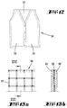
- the fiberboard 2 is a soft fiberboard that with a paraffin latent heat storage material is filled. The filling is made in the form of an impregnation.
- the fibreboard is a fiberboard made of poplar wood fibers, which is comparatively soft when not soaked. However, other cellulose fibers can also be used.
- the fibreboard When not soaked, the fibreboard has a density of approx. 200kg / m 3 . Fiberboard in the density range of 150-300 kg / m 3 is preferred in the unimpregnated state. When impregnated, the fiberboard has a density of approx. 700kg / m 3 . A range of approx. 550-800 kg / m 3 is preferred here.
- the volume fraction of paraffin in the structure matrix is approximately 50%, the mass fraction of the paraffin or latent heat storage material in the matrix is approximately 68%.
- the casing 3 consists of an aluminum foil. It can also be a polypropylene film.
- FIG. It is a latent heat storage 4, in which a plurality of latent heat bodies 1 hanging vertically are arranged.
- the latent heat storage 4 can for example, air flows through it. He can in in the same way but also flowed through by water. This is then in a known manner in the Latent heat bodies 1 the heat stored and in a row then when flowing through with a relatively colder heat transfer medium returned again.
- a latent heat body 40 are all suitable in this context of the embodiments described in the application. According to the illustration, it is provided that at Lower housing 32 attached upper housing 33 the bottom of the upper housing in the area of the recess 35 parallel to the surface in contact with the latent heat bodies 40 stands, so that a good heat transfer between the Animal feed and the latent heat body is given.
- the 6, 7 described feed container can also accommodate additional food types not mentioned in detail become.
- FIG. 9a shows a top view of a heating / cooling ceiling 44 in the expanded state.
- Fig. 9b which is a rolled-up state the ceiling 44 shows in a side view, the ceiling 44 consists of two arranged parallel to each other Fabric layers 45, 45 ', between which a number individually in protective covers, not shown welded latent heat body 46 is sewn.
- FIGS. 9a, 9b are the fabric layers 45, 45 'by seams 47 on the edge and intermediate seams 48 between the latent heat bodies 46 linked together so that an inner cohesion without the risk of latent heat bodies slipping 46 arises.
- the shown heating / cooling cover 44 can be used, for example, as a baby blanket or accident blanket Find application. Flexible are therefore preferred Latent heat bodies 46 are used there, in the case of their carrier material it can be a fleece. While in Fig. 9a in a plan view only a section of a Spread heat / cooling blanket 44 is shown there Fig. 9b in a side view a rolled up Line up a full blanket again. Deviating of the embodiment shown are also training with different form, number and arrangement of Latent heat bodies 46 possible.
- FIG. 10 shows a further application example Top view of a glove 49, in between inner and outer fabric layers, not shown Latent heat bodies 50, 50 'are sewn in.
- Latent heat bodies 50, 50 'are sewn in are also preferred flexible latent heat body used, their carrier material can be a fleece.
- FIG. 11 shows an insole 51 for a shoe. It is then proposed to use a preferably flexible one Properties having latent heat body 52 in a To weld film 53, being on the top and / or Bottom of the sole 52 not shown further Sole layers can be attached. Doing so the bottom of the sole prefers structured layers Materials such as foam or rubber are used be, the slipping of the insole 51 in Prevent shoe. On the top of the sole 51 can preferably textile, for example also padded Fabric layers are used to ensure comfort increase additionally.
- FIG. 13b is a preferred application of a memory element 13a based on a sectional view shown along the section line XVI-XVI.
- the Storage element 58 is then vertical parallel to the surface between two spaced wall elements 60, 60 'arranged.
- Embodiment are also different designs from Network structures possible.
- FIG. 14 uses a schematic sketch to describe a preferred one Use of a latent heat body according to the invention 61 as a storage element for a solar evaporator 62.
- the solar evaporator then has an outer housing 63 on the upper side with high-energy radiation, for example, solar radiation Cover 64, for example a glass plate, closed is.
- an insulating layer 65 is arranged, which consists of conventional Insulating materials, for example polystyrene, are produced can be.
- the side walls of the outer housing with appropriate Insulating layers are equipped.
- About one Inlet 66 is preferably water 67 in the housing initiated, with a desired level under Application of a safety valve 68, which is - as shown - can be a swimmer, is not exceeded.
- a safety valve 68 which is - as shown - can be a swimmer, is not exceeded.
- a feed line 71 air preferably blown in, which is above the water level enriched with water vapor and due to the resulting overpressure through a line 72 in a Consumer escapes 73, which is shown in the Use case is a composter.
- the for the evaporation of the water becomes necessary energy the container by means of the cover 64 energetic radiation supplied.
- a film 79 Not from the surface of the latent heat storage material enclosed by the container part 77 78 is covered by a film 79, which in the manner with the edge of the container part 77 is connected that the latent heat storage material 78 not in the liquefied state from the beverage cooler 74 can emerge.
- the attachment of the film 79 at the edge of the container part 77 can with suitable fasteners 80 done. 15 is as such Fastening the edge of the container part 77 comprehensive profile chosen that runs along extends the entire length of the edge and for example through continuous adhesive layers 81, 82, or in another connecting and sealing way with which Foil 79 and the edge of the container part 77 connected is.
- the fastening element chosen as the profile 80 which in addition to a sealing effect optical function can also be an immediate Sealing between the film 79 and the edge of the container part 77 may be provided. It is preferably provided that the dimensions of the film 79 in stretched Condition exceed the edge distance of the container part 77, so the film 79 wavy or in the initial position wrinkled or overlapping itself more or less irregular on the surface of the latent heat storage material extends. Exemplary shows the sectional view of Fig. 15 shows an arrangement of the film 79 with slats 83.
- a cooling device for example a refrigerator or freezer
- Fig. 16 an arrangement is achieved in which the Beverage container 75 almost completely different from that on it adjacent film 79 and the adjacent latent heat storage material is surrounded.
- the beverage container. 75 stands with the predominant part of it Outer surface via the film 79 in direct heat exchange with the cooled latent heat storage material 78. Because of the very good possible heat conduction from the beverage container into the latent heat storage material becomes a very rapid cooling of the beverage container and the beverage included in it. After a desired cooling of the beverage container or beverage has been reached, the beverage container removed from the beverage cooler. In connection this depends on the deformability the film 79 and the material properties, in particular the surface tension and viscosity, the latent heat storage material 78 to a time-dependent recovery of the latent heat storage material.
- the latent heat storage material can be made from paraffin without a carrier material to achieve advantageous properties one or more of the previously described Contain additives.
Abstract
Description
Die Erfindung betrifft einen Latentwärmekörper mit in einem Aufnahmeräume aufweisenden Trägermaterial aufgenommenem Latentwärmespeichermaterial wie z.B. Paraffin.The invention relates to a latent heat body with in a carrier material having receiving spaces absorbed latent heat storage material such as Paraffin.
Aus dem deutschen Gebrauchsmuster 84 08 966 ist ein
poriges Schaumstoffmaterial als Trägermaterial bekannt.
Bei diesem Schaumstoffmaterial ist jedoch keine auch im
erwärmten Zustand des Latentwärmespeichermaterials gewünschte
Strukturfestigkeit zu erreichen. Überdies ist
das porige Schaumstoffmaterial nicht ohne weiteres mit
dem Latentwärmespeichermaterial zu tränken. Es müssen
besondere Maßnahmen wie Quetschen ergriffen werden.From the
Hiervon ausgehend beschäftigt sich die Erfindung mit der technischen Problematik, einen Latentwärmekörper anzugeben, der bei einfacher Herstellbarkeit hoch wirksam ist, d. h. ein hohes Wärmespeichervermögen aufweist und zugleich auch im erwärmten Zustand eine ausreichende Strukturfestigkeit aufweist. Es ist auch angestrebt, daß das Trägermaterial sich möglichst selbsttätig mit dem Latentwärmespeichermaterial füllt bzw. dieses aufsaugt. Auch ist von Bedeutung, schon aufgrund der Eigenschaften des Trägermaterials ein hohes Rückhaltevermögen bezüglich des Latentwärmespeichermaterials zu erreichen.Proceeding from this, the invention is concerned with the technical problem, a latent heat body specify that is highly effective with simple manufacturability is, d. H. has a high heat storage capacity and at the same time a sufficient one even when heated Has structural strength. It is also aimed that the carrier material with itself as possible fills or absorbs the latent heat storage material. Also important because of its properties of the carrier material has a high retention capacity to achieve with respect to the latent heat storage material.
Diese technische Problematik ist
beim Gegenstand des Anspruches 1 gelöst, wobei
darauf abgestellt ist, daß das Trägermaterial aus einzelnen
für sich strukturfesten oder im Verbund mit dem
Latentwärmespeichermaterial zur Strukturfestigkeit
führenden Trägermaterialelementen beispielsweise durch
Verkleben zusammengesetzt ist.This technical problem is
solved in the subject matter of
Für die Erfindung ist dabei von Bedeutung, daß zwischen den Trägermaterialelementen auch in Abwesenheit von Latentwärmespeichermaterial ein Zusammenhalt besteht, so daß es sich bei dem Trägermaterial um ein oder mehrere Gebilde aus jeweils einer Vielzahl von zusammenhängenden Trägermaterialelementen handelt. Die Trägermaterialelemente sind erfindungsgemäß in der Weise zusammengesetzt, daß zwischen ihnen kapillare Aufnahmeräume für das Latentwärmespeichermaterial ausgebildet sind, die eine spaltartige Form aufweisen können. Die vorbeschriebenen kapillaren Aufnahmeräume ermöglichen aufgrund ihrer kapillaren Zugwirkung auf ein Fluid ein weitgehend selbsttätiges Auffüllen bzw. Aufsaugen des Fluids durch das Trägermaterial sowie ein hohes Rückhaltevermögen desselben. Diese Wirkung wird für den erfindungsgemäßen Latentwärmekörper dadurch angewendet, daß das vorgeschlagene Latentwärmespeichermaterial auf Paraffinbasis, dem einzelne oder mehrere der in dieser Anmeldung angegebenen Zusätze beigegeben sein können, durch Erwärmung soweit verflüssigt wird, bis das selbstständige Aufsaugen zu beobachten ist. Das Latentwärmespeichermaterial wird dabei bis auf eine Temperatur erwärmt, die oberhalb der höchsten Schmelztemperatur der einzelnen darin enthaltenen Paraffine und Zusätze liegt. Das Latentwärmespeichermaterial wird dadurch so stark verflüssigt, daß es bis zur vollständigen Sättigung des Trägermaterials von diesem selbstständig aufgenommen werden kann. Aus dieser Wirkungsweise ergibt sich der Vorteil, daß auf aufwendige und daher kostenintensive technologische Verfahrensschritte unter hoher, insbesondere mechanischer Energiezufuhr verzichtet werden kann. It is important for the invention that between the carrier material elements even in the absence of Latent heat storage material there is cohesion, so that the carrier material is one or more Formations from a large number of connected Carrier elements. The carrier material elements are composed according to the invention in such a way that between them capillary recording spaces for the latent heat storage material is formed, the can have a slit-like shape. The above capillary recording rooms allow due their capillary pulling action on a fluid largely automatic filling or suction of the fluid due to the carrier material and a high retention capacity the same. This effect is for the invention Latent heat body applied by that the proposed latent heat storage material Paraffin base, the single one or more of those in this Additions specified in the registration can be added, is liquefied by heating until the independent Is observed. The latent heat storage material is except for one Temperature warmed above the highest Melting temperature of the individual paraffins contained therein and additives. The latent heat storage material is liquefied so much that it is complete Saturation of the carrier material from this can be recorded independently. From this mode of action there is the advantage that on complex and therefore costly technological process steps with high, especially mechanical energy supply can be dispensed with.
Die zu einem festen Verbund der Trägermaterialelemente untereinander führende Zusammensetzung ist zugleich geeignet, eine Größe der zwischen den Trägermaterialelementen verbleibenden Aufnahmeräume einzustellen und die gewünschte Strukturfestigkeit zu beeinflussen.That to a firm bond of the carrier material elements mutually leading composition is at the same time suitable, a size of between the carrier material elements the remaining recording rooms and the to influence the desired structural strength.
Durch die Einstellbarkeit der Größe der Aufnahmeräume besteht weiterhin die Möglichkeit, in Abhängigkeit von der Grenz- bzw. Oberflächenspannung des Latentwärmespeichermaterialseine hinsichtlich einer größtmöglichen Aufnahmekapazität und einer zugleich ausreichend hohen Kapillarwirkung optimierte Größe der Aufnahmeräume einzustellen.Due to the adjustability of the size of the recording rooms there is still the possibility, depending on the interfacial or surface tension of the latent heat storage material in terms of the greatest possible Absorption capacity and at the same time sufficiently high Capillary effect optimized size of the recording rooms adjust.
Als Trägermaterial kommen organische Materialien wie Kunststoff oder Zellulose in Frage. Bevorzugt ist auch, daß ein Trägermaterialelement eine eigene Kapillarität aufweist. Beispielsweise eine Zellulosefaser, etwa eine Holzfaser, die für sich einen wesentlich feineren Kapillarraum ausbildet als die zwischen zwei Fasern gebildete Kapillarität. Von Bedeutung ist darüber hinaus, daß das Latentwärmespeichermaterial selbst homogen verteilte Hohlstrukturen ausbildet. Diese sind für das Leistungs- bzw. Ansprechverhalten des Latentwärmekörpers von besonderer Bedeutung. Solche Hohlstrukturen erbringen zunächst einmal Ausweichräume im Zuge der Volumenänderung bei Erwärmung oder Abkühlung. Diese Volumenänderunq kann durchaus im Größenbereich von 10% des Volumens liegen. Als Trägermaterialelemente können weiterhin Fasern mit einer sehr unterschiedlichen Länge und einem sehr unterschiedlichen Durchmesser verwendet werden. Geeignet sind insbesondere auch Keramikfasern, Mineralwolle, Kunststoffasern sowie weitere zweckmäßige Fasern, wie beispielsweise Baum- oder Schafwolle. Verwendete Keramikfasern bestehen vorzugsweise im wesentlichen aus Al2O3, SiO2, ZrO2 und organischen Beimischungen, wobei die Anteile der Komponenten stark variieren können. Je nach gewählten Anteilen schwankt auch die Dichte der Keramikfasern und liegt dabei vorzugsweise in einem Bereich zwischen 150 und 400kg/m3. Hinsichtlich der Mineralwolle ist vorzugsweise an einer Verwendung von Steinwolle mit und ohne Zusatz von duroplastischen Kunstharzen gedacht, die weiterhin Glasfaseranteile beinhalten kann. Die Dichte schwankt in Abhängigkeit von der im Einzelfall gewählten Zusammensetzung und liegt dabei vorzugsweise in einem Bereich zwischen 200 und 300kg/m3. Als Trägermaterialelemente geeignete Kunststoffasern weisen vorzugsweise Basismaterialien wie Polyester, Polyamid, Polyurethan, Polyacrylnitril oder Polyolefine auf.Hierzu kann das Latentwärmespeichermaterial ein Paraffin sein, wie es in der DE-OS 43 07 065 beschrieben ist.Organic materials such as plastic or cellulose can be used as the carrier material. It is also preferred that a carrier material element has its own capillarity. For example, a cellulose fiber, such as a wood fiber, which forms a much finer capillary space than the capillarity formed between two fibers. It is also important that the latent heat storage material itself forms homogeneously distributed hollow structures. These are of particular importance for the performance and response behavior of the latent heat body. Such hollow structures initially provide evasive spaces in the course of the change in volume when heated or cooled. This volume change can well be in the size range of 10% of the volume. Fibers with a very different length and a very different diameter can furthermore be used as carrier material elements. Ceramic fibers, mineral wool, plastic fibers and other useful fibers such as cotton or sheep's wool are also particularly suitable. Ceramic fibers used preferably consist essentially of Al 2 O 3 , SiO 2 , ZrO 2 and organic admixtures, the proportions of the components being able to vary widely. Depending on the proportions selected, the density of the ceramic fibers also fluctuates and is preferably in a range between 150 and 400 kg / m 3 . With regard to mineral wool, preference is given to using rock wool with and without the addition of thermosetting synthetic resins, which may also contain glass fiber. The density fluctuates depending on the composition chosen in the individual case and is preferably in a range between 200 and 300 kg / m 3 . Plastic fibers suitable as carrier material elements preferably have base materials such as polyester, polyamide, polyurethane, polyacrylonitrile or polyolefins. The latent heat storage material can also be a paraffin, as described in DE-OS 43 07 065.
Ein solches Paraffin weist im Erstarrungszustand Kristallstrukturen
auf, die durch ein Strukturadditiv vorzugsweise
im Sinne von Hohlstrukturen, wie etwa Hohlkegeln,
modifiziert sind. Hierdurch ist es ermöglicht,
das Ansprechverhalten des Latentwärmespeichermaterials
bei Wärmezufuhr entscheidend zu verbessern. Das
Latentwärmespeichermaterial wie Paraffin nimmt hierdurch
eine gleichsam poröse Struktur an. Bei Wärmezufuhr
können leichter schmelzende Bestandteile des
Latentwärmespeichermaterials durch die im Material
selbst gegebenen Hohlstrukturen hindurchfließen.Es kann
sich, gegebenenfalls auch hinsichtlich vorhandener
Lufteinschlüsse eine Art Mikro-Konvektion einstellen. Es
ergibt sich auch eine hohe Durchmischungswirksamkeit.
Im weiteren ist auch eine Vorteilhaftigkeit hinsichtlich
des bereits angesprochenen Ausdehnungsverhaltens
bei Phasenänderung gegeben. Das Strukturadditiv ist in
dem Latentwärmespeichermaterial vorzugsweise homogen
gelöst. Im einzelnen haben sich Strukturadditive wie
solche auf Basis von Polyalkylmetacrylaten (PA-MA) und
Polyalkylacrylaten (PAA) als Einzelkomponenten oder in
Kombination bewährt. Ihre kristallmodifizierende Wirkung
wird dadurch hervorgerufen, daß die Polymermoleküle
in die wachsenden Paraffinkristalle mit eingebaut
werden und das Weiterwachsen dieser Kristallform verhindert
wird. Aufgrund des Vorliegens der Polymermoleküle
auch in assoziierter Form in der homogenen Lösung in
Paraffin können auf die speziellen Assoziate Paraffine
aufwachsen. Es werden Hohlkegel gebildet, die nicht
mehr zur Bildung von Netzwerken befähigt sind. Aufgrund
der synergistischen Wirkungsweise dieses Strukturadditives
auf das Kristallisationsverhalten der Paraffine
wird eine Hohlraumbildung und damit eine Verbesserung
der Durchströmbarkeit des Wärmespeichermediums Paraffin
(beispielsweise für in dem Latentwärmespeicherkörper
eingeschlossene Luft oder Wasserdampf oder für verflüssigte
Phasen des Latentwärmespeichermaterials, d. h.
des Paraffins selbst) gegenüber nicht derartig compoundierten
Paraffinen erreicht. Allgemein eignen sich
als Strukturadditive auch Ethylen, Venylacetat-Copolymere
(E, VA ), Ethylen-Propylen-Copolymere (OCP),
Dien-Styrol-Copolymere sowohl als Einzelkomponenten als
auch im Gemisch sowie alkylierte Naphthaline (Paraflow).
Der Anteil der Strukturadditive fängt bei einem
Bruchteil von Gewichtsprozenten, realistischerweise
etwa bei 0.01 Gewichtsprozent an und zeigt insbesondere
bis zu einem Anteil von etwa einem Gewichtsprozent
spürbare Veränderungen im Sinne einer Verbesserung.In the solidification state, such a paraffin has crystal structures which are modified by a structural additive, preferably in the sense of hollow structures, such as hollow cones. This makes it possible to decisively improve the response behavior of the latent heat storage material when heat is added. As a result, the latent heat storage material such as paraffin takes on a porous structure. When heat is added, components of the latent heat storage material that melt more easily can flow through the hollow structures provided in the material itself. A type of micro-convection can also occur, if necessary also with regard to air pockets. There is also a high mixing efficiency.
Furthermore, there is also an advantage with regard to the expansion behavior already mentioned in the event of a phase change. The structural additive is preferably dissolved homogeneously in the latent heat storage material. Structural additives such as those based on polyalkyl methacrylates (PA-MA) and polyalkylacrylates (PAA) as individual components or in combination have proven successful. Their crystal-modifying effect is brought about by the fact that the polymer molecules are incorporated into the growing wax crystals and the further growth of this crystal form is prevented. Due to the presence of the polymer molecules in an associated form in the homogeneous solution in paraffin, paraffins can grow on the special associates. Hollow cones are formed that are no longer able to form networks. Due to the synergistic mode of action of this structural additive on the crystallization behavior of the paraffins, void formation and thus an improvement in the flowability of the paraffin heat storage medium (for example for air or water vapor enclosed in the latent heat storage body or for liquefied phases of the latent heat storage material, that is to say the paraffin itself) is not so paraffins reached. Ethylene, vinyl acetate copolymers (E, VA), ethylene-propylene copolymers (OCP), diene-styrene copolymers, both as individual components and in a mixture, and also alkylated naphthalenes (Paraflow) are also generally suitable as structural additives. The proportion of structural additives starts at a fraction of a percent by weight, realistically around 0.01 percent by weight, and in particular shows noticeable changes in the sense of improvement up to a proportion of about one percent by weight.
Dem Latentwärmespeichermaterial kann ein Zusatz zugesetzt sein, welcher zur Dickflüssigkeit führt. Es kann hier ein übliches Thixotropiemittel verwendet werden. Selbst im erwärmten Zustand, in welchem üblicherweise eine Verflüssigung des Latentwärmespeichermaterials gegeben ist, ist dann noch eine Schwerflüssigkeit, im Sinne einer gallertartigen Konsistenz, gegeben. Selbst bei einem unbeabsichtigten Durchtrennen eines solchen Latentwärmespeicherkörpers kommt es noch nicht oder nicht in wesentlichem Ausmaß zu einem Auslaufen von Latentwärmespeichermaterial.The An additive can be added to latent heat storage material. which leads to thick fluid. It can be here Usual thixotropy agent can be used. Even in warmed state, in which is usually a liquefaction given the latent heat storage material is then still a heavy liquid, in the sense a gelatinous consistency. Even at an unintentional severing Latent heat storage body does not come yet or not to a significant extent to a leak from Latent heat storage material.
Bevorzugt ist ein so gebildeter Latentwärmekörper auch vollständig mit einer Abdeckung, bevorzugt einer Kunststoffolie umschlossen. Die vollständige Umhüllung verhindert ein Auslaufen etwa erweichten oder verflüssigten Latentwärmespeichermaterials. Die Umhüllung kann beispielsweise auch mit Harnstoff vorgenommen werden. Die Platte kann in einen aufgeschmolzenen Umhüllungsstoff, also beispielsweise Harnstoff oder auch einen Kunststoff, wie etwa Nylon (Polyamid), eingetaucht werden. Bei Harnstoff ergibt sich der Vorteil einer stark brandhemmenden Wirkung. Die Verhinderung des Auslaufens ist insbesondere von Bedeutung bei Überschreiten der Nennbetriebsparameter. Dies gilt insbesondere bei Überschreiten der Nennbetriebsparameter.A latent heat body formed in this way is also preferred completely with a cover, preferably a plastic film enclosed. The complete wrapping prevents leakage, for example, softened or liquefied Latent heat storage material. The wrapping can for example, can also be made with urea. The plate can be wrapped in a melted wrapping material, for example urea or one Plastic, such as nylon (polyamide), dipped become. With urea there is the advantage of one strong fire-retardant effect. Preventing the Leakage is particularly important when exceeding the nominal operating parameter. This is especially true if the nominal operating parameters are exceeded.
Bevorzugt besteht die Trägerstruktur aus einem aus Einzelfasern zusammengesetzten Faserkörper. Hierbei können handelsübliche Faserplatten zum Einsatz kommen, wobei jedoch relativ weiche Faserplatten bevorzugt sind. Hartfaserplatten können nur im geringen Maße das Latentwärmespeichermaterial aufnehmen. Die Fasern sind bevorzugt selbst saugfähig. Beim Tränken einer solchen Faserplatte mit einem Latentwärmespeichermaterial auf Paraffinbasis saugen sich die Fasern mit Paraffin voll, werden "gewachst". Zudem werden auch noch die Kapillarräume zwischen den Fasern mit dem Latentwärmespeichermaterial gefüllt. Eine weitere Ausgestaltung sieht als Trägermaterial ein Vlies, beispielsweise ein übliches Saugvlies, vor, wie es etwa zum Aufsaugen von Öl, Säuren oder sonstigen Flüssigkeiten handelsüblich ist. Insbesondere kann es ein vollständig aus Polypropylenfasern bestehendes Vlies sein. Hierbei können die Fasern auch im Sinne der eingangs genannten allgemeinen Lehre miteinander verhaftet, beispielsweise verschweißt sein. Die Trägerstruktur des Vlieses hat aber auch unabhängig hiervon Bedeutung. Von besonderem Vorteil ist, daß sich die erwähnte Fasermatte und auch das Vlies beim Tränken mit dem Latentwärmespeichermaterial auf Paraffinbasis verfestigen. Die Struktur wird steifer. Beispielsweise wird eine derartige Faserplatte hierdurch druckfester und beispielsweise trittfest. Zudem verbessern sich auch die schalltechnischen Eigenschaften so geschaffener Latentwärmekörper. Es ist eine höhere Körperschalldämpfung zu beobachten. Der Trittschall, etwa bei Verwendung eines solchen Latentwärmekörpers im Fußbodenbereich, wird wirksam gedämpft. In weiterer vorteilhafter Ausgestaltung werden solche Trägerstrukturen verwendet, die eine zwei- bis zehnfache Tränkung mit Latentwärmespeichermaterial im Vergleich zu ihrem Eigengewicht ermöglichen. Bei den erwähnten Faserplatten wird beispielsweise eine drei- bis vierfache Tränkung mit Latentwärmespeichermaterial vorgenommen. Gleichwohl wird die Tränkung nicht soweit vorgenommen, daß Überquelleffekte entstehen. Es empfiehlt sich auch, einen äußeren Verschluß der Kapillaren, etwa durch Verschleifen, vorzunehmen. Dieser Verschluß wirkt noch zusätzlich zu der erwähnten Umhüllung. Hierbei ist es bevorzugt, daß der Verschluß der Kapillaren vor dem Tränken des Trägermaterials mit dem Latentwärmespeichermaterial vorgenommen wird.The carrier structure preferably consists of one Single fiber composite fiber body. Here commercially available fiberboard can be used, however, relatively soft fiberboard is preferred are. Hardboard can only do that to a small extent Absorb latent heat storage material. The fibers are preferably self-absorbent. When watering one Fiberboard with a latent heat storage material Paraffin-based, the fibers absorb paraffin full, are "waxed". In addition, the Capillary spaces between the fibers with the latent heat storage material filled. Another configuration sees a nonwoven, for example a carrier material usual absorbent fleece, as it is about to soak up Oil, acids or other liquids are commercially available is. In particular, it can be made entirely of polypropylene fibers existing fleece. Here, the Fibers also in the sense of the general mentioned at the beginning Teaching arrested, for example welded together his. The carrier structure of the fleece also has regardless of meaning. Of particular advantage is that the aforementioned fiber mat and that Fleece when soaking with the latent heat storage material solidify on paraffin base. The structure becomes stiffer. For example, such a fiberboard hereby more pressure-resistant and, for example, tread-resistant. The acoustic properties also improve thus created latent heat body. It is one to observe higher structure-borne noise attenuation. The impact sound, such as when using such a latent heat body in the floor area, is effectively dampened. In further advantageous embodiments are Support structures used that are two to ten times Impregnation with latent heat storage material in comparison allow for their own weight. With the mentioned Fiberboard is, for example, a three to fourfold impregnation with latent heat storage material performed. Nevertheless, the watering does not go that far made that overflow effects arise. It recommends itself, an external closure of the capillaries, for example by grinding. That closure acts in addition to the aforementioned wrapping. It is preferred that the closure of the Capillaries before soaking the carrier material with the Latent heat storage material is made.
Eine weitere besondere Lehre der Erfindung betrifft
eine Ausgestaltung des Latentwärmespeichermaterials auf
Paraffinbasis derart, daß auch im verfestigten Zustand
noch eine Flexibilität gegeben ist. In Kombination mit
den Trägermaterialelementen kann so ein flexibles Element,
wie beispielsweise ein Sitzkissen oder eine Bandage
erreicht werden. Hierzu ist vorgesehen, daß das
Latentwärmespeichermaterial - auf Paraffinbasis - einen
Anteil an Mineralöl und/oder an Polymeren, Kautschuken
und/oder Elastomeren enthält. Die Kautschuke und/oder
Elastomere führen vorrangig zu einer höheren Flexibilität.
Sie sind mit weniger als 5 % Anteil enthalten.
Wenn die Polymere keine Elastomere sind, führen sie zu
keiner Erhöhung der Flexibilität und verhindern nur,
gegebenenfalls zusätzlich, ein Auslaufen. Vorzugsweise
handelt es sich um hochausraffiniertes Mineralöl. Beispielsweise
ein Mineralöl, welches man üblicherweise
auch als Weißöl bezeichnet. Bei den Polymeren handelt
es sich um vernetzte Polymere, die durch Copolymerisation
hergestellt sind. Die vernetzten Polymere bilden
mit dem Mineralöl durch Ausbildung eines dreidimensiona-.
len Netzwerkes oder durch ihre physikalische Vernetzung
(Knollenstruktur) eine gelartige Struktur. Diese Gele
besitzen eine hohe Flexibilität bei gleichzeitiger
Stabilität gegenüber einwirkenden mechanischen Kräften.
Das Paraffin wird im flüssigen Zustand in diese Struktur
eingeschlossen. Bei dem Phasenwechsel, der Kristallisation,
werden die entstehenden Paraffinkristalle von
der Gelstruktur umgeben, so daß sich eine flexible
Gesamtmischung ergibt.Another particular teaching of the invention relates to an embodiment of the latent heat storage material based on paraffin in such a way that there is still flexibility even in the solidified state. In combination with the carrier material elements, a flexible element such as a seat cushion or a bandage can be achieved. For this purpose, it is provided that the latent heat storage material - based on paraffin - contains a proportion of mineral oil and / or of polymers, rubbers and / or elastomers. The rubbers and / or elastomers primarily lead to greater flexibility. They are included with less than 5%.
If the polymers are not elastomers, they do not lead to an increase in flexibility and only prevent, if necessary additionally, leakage. It is preferably a highly refined mineral oil. For example, a mineral oil, which is commonly referred to as white oil. The polymers are crosslinked polymers which are produced by copolymerization. The cross-linked polymers form with the mineral oil by forming a three-dimensional. len network or through their physical networking (tuber structure) a gel-like structure. These gels are extremely flexible and at the same time stable against mechanical forces. The liquid paraffin is enclosed in this structure. During the phase change, the crystallization, the resulting wax crystals are surrounded by the gel structure, so that a flexible overall mixture results.
In einer möglichen Anwendung kann ein Latentwärmespeichermaterial, das Paraffin mit einer Schmelztemperatur von 50° Celsius und ein Copolymer mit einer Schmelztemperatur von 120° Celsius enthält, bis zu einer Temperatur von 125° Celsius aufgeheizt werden, so daß zunächst eine gleichmäßige Durchmischung beider Komponenten erreicht wird und die dünnflüssige Mischung vom Trägermaterial aufgrund der darin wirksamen Kapillarkräfte bis zur vollständigen Sättigung aufgenommen werden kann. Bei einer nachfolgenden Abkühlung werden die entstehenden Paraffinkristalle von dem Copolymer umgeben. Bei einer z. B. denkbaren oberen Betriebstemperatur des Latentwärmekörpers von 80° Celsius wird nur der Paraffinanteil, nicht dagegen das Copolymer, verflüssigt. Vorteilhaft wird dadurch erreicht, daß das Paraffin nicht aus dem Copolymer austreten kann und mit ihm im Trägermaterial verbleibt. Für die Erfindung ist wesentlich, daß das gewünschte Paraffinrückhaltevermögen in dem Latentwärmekörper bei Verwendung des oben beschriebenen Trägermaterials bereits bei einem Massenanteil von weniger als 5 % des Copolymers am Latentwärmespeichermaterial erzielt werden kann. Dabei kann insbesondere durch ein gezielt herbeigeführtes Zusammenwirken von Kapillarkräften in den Aufnahmeräumen des Trägermaterials und/oder von mittels Strukturadditiven beeinflußten Kristallstrukturen der Paraffine und/oder von den das Latentwärmespeichermaterial verdikkenden Thixotropiemitteln und/oder durch den beschriebenen Verschluß der Kapillaren sowie gegebenenfalls einer Umhüllung des Latentwärmekörpers erreicht werden, daß das gewünschte Paraffinrückhaltevermögen bereits bei deutlich niedrigeren Massenanteilen des Copolymers als 5 % erreicht wird. Ein Vorteil der Erfindung ist dabei darin gegeben, daß mit abnehmendem Massenanteil von Copolymeren der Massenanteil der Paraffine an der Gesamtmasse des Latentwärmespeichermaterials zunimmt und dadurch bei unveränderter Gesamtmasse eine höhere Wärmekapazität erreicht werden kann.In one possible application, a latent heat storage material, the paraffin with a melting temperature of 50 ° Celsius and a copolymer with a melting temperature contains from 120 ° Celsius up to a temperature heated by 125 ° Celsius, so that first uniform mixing of both components is reached and the thin mixture of Carrier material due to the capillary forces in it added until full saturation can be. With a subsequent cooling the resulting wax crystals from the copolymer surround. At a z. B. conceivable upper operating temperature of the latent heat body of 80 ° Celsius is only the paraffin portion, but not the copolymer, liquefies. It is advantageously achieved that the Paraffin cannot escape from the copolymer and with remains in the carrier material. For the invention essential that the desired paraffin retention in the latent heat body using the above described carrier material already with a mass fraction less than 5% of the copolymer Latent heat storage material can be achieved. there can be brought about in particular by a specifically brought about Interaction of capillary forces in the recording rooms the carrier material and / or by means of structural additives influenced crystal structures of the paraffins and / or those that thicken the latent heat storage material Thixotropic agents and / or by the described Closure of the capillaries and possibly one Wrapping the latent heat body can be achieved that the desired paraffin retention capacity significantly lower proportions by weight of the copolymer than 5% is reached. One advantage of the invention is that given that with decreasing mass fraction of Copolymers the mass fraction of paraffins in the Total mass of the latent heat storage material increases and thereby a higher with unchanged total mass Heat capacity can be achieved.
Zusammen mit dem oben näher beschriebenen Trägermaterial ergibt sich auch eine gewünschte Strukturfestigkeit, im Rahmen der Flexibilität. Hierbei können aber auch noch weitere Trägermaterialien als oben beschrieben zur Anwendung kommen. Hinsichtlich der Polymere werden beispielsweise Styrol-Butadien-Styrol (SBS), Styrol-Isopren-Styrol (SIS) oder Styrol-Ethylen/Butylen-Styrol (S-EB-S) eingesetzt. Dieses Styrol-Ethylen /Butylen Block-Copolymer eignet sich als Verdicker zur Erhöhung der Viskosität bzw. als Flexibilisator zur Erhöhung der Elastizität. Bei einem thermoplastischen Kunststoff existieren mehrere Typen von Copolymeren, die sich in ihrem strukturellen Aufbau unterscheiden. Zu unterscheiden sind dabei insbesondere die Block- und Triblock-Copolymere, deren Molgewicht variiert und die ein unterschiedliches Verhältnis von Styrol- zu Elastomeranteil aufweisen. Together with the carrier material described in more detail above there is also a desired structural strength, in the context of flexibility. This can also still more carrier materials than described above for Application come. Regarding the polymers, for example Styrene-butadiene-styrene (SBS), styrene-isoprene-styrene (SIS) or styrene-ethylene / butylene-styrene (S-EB-S) used. This styrene-ethylene / butylene Block copolymer suitable as a thickener to increase the viscosity or as Flexibilizer to increase elasticity. At a thermoplastic there are several types of copolymers, which are in their structural Differentiate construction. A distinction must be made here the block and triblock copolymers, their molecular weight varies and the ratio is different from styrene to elastomer.
Weiterhin können auch Copolymere, wie beispielsweise HDPE (High Density Polyethylen), PP (Polypropylen) oder auch HDPP (High Density Polypropylen) verwendet werden.Copolymers, such as, for example, may also be used HDPE (high density polyethylene), PP (polypropylene) or HDPP (high density polypropylene) can also be used.
Gegenstand der Anmeldung ist auch ein Latentwärmespeichermaterial auf Paraffinbasis, welches einen Zusatz in einer der vorstehend beschriebenen Ausgestaltungen aufweist. Sowohl der Latentwärmekörper wie auch das Latentwärmespeichermaterial können darüber hinaus und in Kombination ein Additiv aufweisen, das die oben erwähnten Hohlstrukturen ausbildet.The application also relates to a latent heat storage material on paraffin base, which an addition in one of the configurations described above having. Both the latent heat body and that Latent heat storage material can also and have in combination an additive that the above forms mentioned hollow structures.
Das erfindungsgemäße Latentwärmespeichermaterial auf Paraffinbasis kann weiterhin auch ohne Trägermaterial, d. h. ohne stützende Matrix eingesetzt werden. Aus Schmelz-/Speicherkapazitäts- und Funktionsgründen ist der Copolymeranteil stets kleiner als 5 %. Das gebildete Gel wird in Behälterhüllen, wie bspw. Foliensäcken, aufgenommen.The latent heat storage material according to the invention Paraffin base can also be used without a base material, d. H. can be used without a supporting matrix. Out Melting / storage capacity and functional reasons the copolymer content always less than 5%. The educated Gel is in container casings, such as foil bags, added.
Wesentlich ist, daß sich der erwähnte Zusatz aus Mineralölen und Polymeren einerseits homogen in dem Paraffin verteilt bzw. das Paraffin diesen Zusatz homogen durchsetzt und andererseits keine chemische Wechselwirkung zwischen dem Zusatz und dem Paraffin eintritt. Weiter ist von besonderer Bedeutung, daß die Auswahl dahingehend getroffen ist, daß praktisch keine Dichteunterschiede zwischen dem Zusatz und dem Paraffin gegeben sind, so daß auch keine physikalische Entmischung hierdurch auftreten kann.It is essential that the additive mentioned is made from mineral oils and polymers on the one hand homogeneous in the paraffin distributed or the paraffin homogeneously this addition enforced and on the other hand no chemical interaction between the additive and the paraffin. It is also of particular importance that the selection is taken to the effect that practically no density differences between the additive and the paraffin are, so that no physical segregation as a result can occur.
Wie bereits eingangs erläutert, besteht in Verbindung mit einzelnen oder mehreren der vorangehend erläuterten Merkmalen die Möglichkeit, daß der erfindungsgemäße Latentwärmekörper eine Anzahl Latentwärmeteilkörper enthält. Bei einem Latentwärmeteilkörper handelt es sich um einen zusammenhängenden und abgegrenzten Teil, bzw. Bestandteil eines erfindungsgemäßen Latentwärmekörpers, der sämtliche physikalischen, chemischen und baulich strukturellen Merkmale des Latentwärmekörpers oder auch eine beliebige Auswahl hiervon auf sich vereinigen kann. Bevorzugt enthält ein Latentwärmeteilkörper ein Trägermaterialteil und das in kapillarartigen Aufnahmeräumen dieses Trägermaterialteils aufgenommene Latentwärmespeichermaterial. Das angesprochene Trägermaterialteil kann beliebige Kombinationen der bisher erläuterten Merkmale eines Trägermaterials aufweisen. In einer bevorzugten Ausführungsform enthält der Latentwärmekörper eine von seiner Form und Größe mitbestimmte größere Anzahl von Latentwärmeteilkörpern, die regelmäßig und/oder unregelmäßig aneinander angrenzend angeordnet werden können. Auf diese Weise lassen sich Latentwärmekörper nahezu beliebiger Formen auf preiswerte Weise herstellen, da die Latentwärmeteilkörper unabhängig von der Form der gewünschten Latentwärmekörper industriell in großer Stückzahl hergestellt werden können. In einer bevorzugten Ausgestaltung eines aus mehreren Latentwärmeteilkörpern gebildeten Latentwärmekörpers grenzen auch die in den Latentwärmeteilkörpern eingeschlossenen Trägermaterialteile aneinander. Diese sind deutlich von den Trägermaterialelementen zu unterscheiden, aus denen das Trägermaterial, wie oben erläutert, durch beispielsweise Verkleben zusammengesetzt ist. Innerhalb einzelner Trägermateralteile bilden danach die Trägermaterialelemente unter Einschluß kapillarartiger Aufnahmeräume zusammenhängende Strukturen. Auch zwischen benachbarten Latentwärmeteilkörpern kann jedoch ein Zusammenhalt bestehen, indem es beispielsweise zum gegenseitig verhakenden Eingriff von Trägermaterialelementen aneinander angrenzender Trägermaterialteile in die jeweilig benachbarten zusammenhängenden Strukturen kommt. Ein weiterer Zusammenhalt zwischen Latentwärmeteilkörpern ist dadurch möglich, daß eine Verbindung des Latentwärmespeichermaterials von aneinandergrenzenden Latentwärmeteilkörpern zustande kommt.As already explained at the beginning, there is a connection with one or more of the above Features the possibility that the invention Latent heat body a number of latent heat partial body contains. A latent heat partial body is involved is a coherent and delimited part, or part of an inventive Latent heat body, which all physical, chemical and structural features of the latent heat body or any selection of these can unite. Preferably contains one Latent heat partial body a carrier material part and that in capillary-like receiving spaces of this carrier material part absorbed latent heat storage material. The Carrier material part addressed can be any combination the features of a carrier material explained so far exhibit. In a preferred embodiment the latent heat body contains one of its shape and Size with certain larger number of latent heat partial bodies, who regularly and / or irregularly to each other can be arranged adjacent. To this In this way, latent heat bodies can be made almost arbitrarily Manufacture molds in an inexpensive way because the latent heat partial body regardless of the shape of the desired Latent heaters manufactured industrially in large numbers can be. In a preferred embodiment one formed from several latent heat partial bodies Latent heat bodies also limit those in the partial latent heat bodies enclosed carrier material parts to each other. These are clear from the backing material elements to distinguish from which the carrier material, as explained above, for example by gluing is composed. Within individual carrier material parts then form the carrier material elements under Inclusion of capillary-like receiving spaces contiguous Structures. Also between neighboring latent heat partial bodies however, there can be cohesion for example, to hook each other Engagement of carrier material elements adjacent to one another Carrier parts in the neighboring connected structures comes. Another cohesion is between latent heat partial bodies possible that a connection of the latent heat storage material of adjacent latent heat partial bodies comes about.
Bevorzugt weist das Volumenverhältnis von Latentwärmekörper
zu Latentwärmeteilkörper zumindest den Wert 10
auf, wobei allerdings auch geringere oder wesentlich
höhere Volumenverhältnisse sinnvoll sein können. Ein
einzelner Latentwärmekörper kann außerdem Latentwärmeteilkörper
verschiedener Größenabmessungen
und/oder verschiedener Formen beinhalten. Desweiteren
besteht auch die Möglichkeit, daß einzelne Latentwärmeteilkörper
eine langgestreckte Form besitzen und
zumindest im weitesten Sinne als Streifen ausgebildet
sind. Alternativ kann ein Latentwärmeteilkörper auch
eine flockenartige Form besitzen. Darüber hinaus können
die Latentwärmeteilkörper auch in Form von Kugeln,
Ellipsoiden, Quadern, Würfeln, Pyramiden, Zylindern und
dergleichen ausgebildet werden. Die Auswahl der Anzahl,
der Größen und der Formen der Latentwärmeteilkörper
eines Latentwärmekörpers kann sich dabei an der Größe
und Form des gewünschten Latentwärmekörpers sowie an
den an ihn gerichteten Forderungen bezüglich seiner
Steifigkeit oder Verformungsfähigkeit orientieren. In
einer weiter bevorzugten Ausführung des Latentwärmeteilkörpers
weist dieser eine Umhüllung auf, die beispielsweise
aus einem Folienmaterial, insbesondere aus
einer Aluminiumfolie oder aus einer Polypropylenfolie,
besteht. Eine Folie bietet dabei den Vorteil einer
leichten Verformbarkeit, so daß sich benachbarte
Latentwärmeteilkörper aneinander anschmiegen können und
Hohlräume zwischen den Latentwärmeteilkörpern weitgehend
vermieden werden können. Alternativ oder in Verbindung
damit besteht die Möglichkeit, daß auch eine Anzahl
benachbarter Latentwärmeteilkörper mit einer gemeinsamen
äußeren Umhüllung versehen sind, bei der es
sich ebenfalls um eine der vorhergenannten Folien handeln
kann. Weiterhin besteht die Möglichkeit, daß die
gemeinsame äußere Umhüllung eine vergleichsweise feste,
d.h. verglichen mit dem Latentwärmekörper bzw. den
Latentwärmeteilkörpern schwerer verformbare Wandung
aufweist. Sofern eine derartige feste Wandung als Hohlkörper
ausgebildet ist, kann dessen Innenraum selbst
bei komplizierten geometrischen Formen der gemeinsamen
äußeren Umhüllung nahezu vollständig mit Latentwärmeteilkörpern
jeweils bedarfsgerechter Größe, Form und Anzahl
ausgefüllt sein. Die Latentwärmeteilkörper können
dabei zur Verhinderung von größeren Hohlräumen in der
festen gemeinsamen Umhüllung mit einem Druck beaufschlagt
sein, so daß zumindest bereichsweise eine Verdichtung
erzielt wird. Bei derart verdichteten Latentwärmeteilkörpern
eines Latentwärmekörpers kann der
Volumenanteil von Hohlräumen zwischen Latentwärmeteilkörpern
z.B. weniger als 1 % Anteil am Gesamtvolumen
des Latentwärmekörpers betragen. Die Umhüllung der
einzelnen Latentwärmeteilkörper und/oder die gemeinsame
Umhüllung der Latentwärmeteilkörper eines Latentwärmekörpers
sind dabei bevorzugt so ausgestaltet, daß sie
für Latentwärmespeichermaterial undurchlässig sind.The volume ratio of latent heat body preferably has
for latent heat partial bodies at least the
In einer alternativen vorteilhaften Ausgestaltung eines Latentwärmekörpers enthält dieser einer Mehrzahl von Latentwärmeteilkörpern, die von einer gemeinsamen, für einen Wärmeträger durchlässigen Hülle umgeben sind und die darin vorzugsweise voneinander beabstandet sind. Durch die Beabstandung der Latentwärmeteilkörper werden zwischen ihnen Hohlräume ausgebildet, die als Strömungswege für das Wärmeträgermedium geeignet sind. Insbesondere ist vorgesehen, daß ein Wärmeträgermedium aus einer äußeren Umgebung durch die dafür durchlässige äußere Umhüllung des Latentwärmekörpers in dessen Inneres tritt, dort die zwischen den Latentwärmeteilkörpern gebildeten Hohlräume durchströmt und anschließend durch die dafür durchlässige gemeinsame Umhüllung des Latentwärmekörpers wieder aus diesem hinaustritt. Ein auf diese Weise in seinem Inneren durchströmter Latentwärmekörper zeichnet sich durch eine besonders schnelle Wärmeübertragung von oder zu einem Wärmeträgermedium aus. Die gemeinsame Umhüllung der Latentwärmeteilkörper kann bspw. netz- oder gitterartig ausgebildet sind, d.h. es ist sowohl an leicht verformbare als auch an starre Strukturen gedacht. Die Ein- und Austrittsöffnungen der gemeinsamen äußeren Umhüllung der im Latentwärmekörper enthaltenen Latentwärmeteilkörper sind zweckmäßig so bemessen, daß ein weitgehend ungehinderter Ein- und Austritt des Wärmeträgermediums in bzw. aus dem Latentwärmekörper ermöglicht wird und daß dabei außerdem kein Latentwärmeteilkörper durch sie hindurchtreten können. Das Volumenverhältnis zwischen den in der Umhüllung enthaltenen Latentwärmeteilkörpern und den dazwischen befindlichen Hohlräumen kann in einem weiten Wertebereich liegen und dabei zahlenmäßig den Wert Eins deutlich über- oder unterschreiten. Sofern als Wärmeträgermedium eine Flüssigkeit verwendet wird, können die Latentwärmeteilkörper in ihrer Massendichte in der Weise eingestellt werden, daß sie im Wärmeträgermedium in der Schwebe gehalten werden. Auf diese Weise werden die gebildeten Hohlräume aufrechterhalten, wobei jedoch eine weitere Beschleunigung des Wärmeaustausches mit den Latentwärmeteilkörpern durch deren strömungsbedingte Zirkulation erreicht werden kann. Als flüssiges Wärmeträgermedium eignen sich bspw. Wasser oder Öle und darüber hinaus auch zweckmäßige andere Flüssigkeiten. Auch bei Verwendung eines gasförmigen Wärmeträgermediums, z.B. Luft, kann eine Resimentation der in der gemeinsamen Umhüllung enthaltenen Latentwärmeteilkorper durch eine gezielt herbeigeführte Strömung entgegengewirkt werden, die zu einer ständigen Schwebe bzw. Zirkulation der Latentwärmeteilkörper führt. Dies kann durch eine spezielle Ausgestaltung der Latentwärmeteilkörper begünstigt werden, bei der eine jeweils größere Oberfläche im Verhältnis zum Gewicht eines jeweiligen Latentwärmeteilkörpers verwirklicht ist. Gedacht ist bspw. an eine flockenartige Ausgestaltung der Latentwärmeteilkörper. Im übrigen können die Latentwärmeteilkörper einzelne oder mehrere der zuvor genannten Merkmale aufweisen.In an alternative advantageous embodiment of a Latent heat body contains a plurality of Latent heat partial bodies by a common, for are surrounded by a heat-permeable shell and which are preferably spaced apart from one another. By spacing the latent heat partial body cavities formed between them as flow paths are suitable for the heat transfer medium. In particular it is provided that a heat transfer medium an external environment through the permeable outer wrapping of the latent heat body inside occurs there between the latent heat sub-bodies flows through the cavities formed and then through the permeable joint covering of the latent heat body steps out of this again. One on this way, latent heat body through which it flows is characterized by a particularly fast Heat transfer from or to a heat transfer medium out. The common covering of the latent heat part body can, for example, be network or grid-like, i.e. it is both easy to deform and attached to rigid structures thought. The entry and exit openings the common outer envelope of the latent heat body contained latent heat partial body appropriately dimensioned so that a largely unhindered Entry and exit of the heat transfer medium in or is made possible from the latent heat body and that in addition, no latent heat partial body pass through it can. The volume ratio between the in the casing contained latent heat partial bodies and the cavities in between can be in one wide range of values and numerically the Significantly exceed or fall below value one. Provided a liquid is used as the heat transfer medium, can the latent heat partial body in their mass density be set in such a way that they are in the heat transfer medium to be held in suspense. In this way the cavities formed are maintained, whereby however, a further acceleration of the heat exchange with the latent heat partial bodies due to their flow-related Circulation can be achieved. As a liquid Heat transfer medium are, for example, water or oils and in addition also useful other liquids. Even when using a gaseous heat transfer medium, e.g. Air, a resimentation of the in the common envelope contained latent heat partial body counteracted by a specifically induced flow become a constant floating or circulation the latent heat partial body leads. This can be done by a special configuration of the latent heat partial body be favored, each with a larger surface in relation to the weight of a respective latent heat partial body is realized. For example, it is thought of a flake-like configuration of the latent heat partial body. Otherwise, the latent heat partial body one or more of the aforementioned features exhibit.
Ein wie vorstehend ausgebildeter Latentwärmekörper kann, wie bereits angesprochen, als Fußbodenelement in eine Fußbodenheizung eingebaut werden.A latent heat body designed as above can, as already mentioned, as a floor element in underfloor heating can be installed.
Die Erfindung betrifft aber auch noch weitere Anwendungen solcher Latentwärmekörper.However, the invention also relates to further applications such latent heat body.
Eine erste Anwendung besteht aus einem Plattenwärmetauscher, der als Platten solche Latentwärmekörper aufweist. Die Plattenelemente können dann beidseitig mit Medium beaufschlagt werden. Beispielsweise können hiermit auch regenerative Wärmetauscher, wie sie etwa in Wärmekraftwerken bekannt sind, ausgerüstet werden. Im einzelnen kann ein solches Plattenelement auch spiralförmig ausgebildet sein. Zur Ausbildung und Aufrechterhaltung der spiralförmigen Gestaltung, was aber auch auf ebenflächige Plattenelemente zutrifft, sind zwischen den Lagen Abstandselemente angeordnet. Diese sind gitterartig gestaltet derart, daß Durchströmwege offen sind.A first application consists of a plate heat exchanger, which has such latent heat bodies as plates. The plate elements can then be used on both sides Medium are applied. For example, you can use this also regenerative heat exchangers, such as those in Thermal power plants are known to be equipped. in the Such a plate element can also be individual in spiral form be trained. For training and maintenance the spiral shape, but what about flat plate elements are between the layers spacers arranged. These are designed like a lattice in such a way that flow paths are open are.
In weiterer Ausführungsform ist bevorzugt, daß ein solches Plattenelement als Fassadenelement im Hausbau ausgebildet ist. Hierbei ist es besonders vorteilhaft, wenn das Fassadenelement mit Abstand zu einer Hauswand angeordnet ist. Die sich dann zwischen der Hauswand und dem Fassadenelement, das hierbei als Latentwärmespeicherelement ausgebildet ist, einstellende Kaminwirkung kann hierdurch einen Kühleffekt erbringen, auch durch Wärmespeicherung in dem Latentwärmekörper. Im weiteren wird auch das thermische Zeitverhalten verbessert. Etwa nach Sonnenuntergang gibt der Latentwärmekörper noch über lange Zeit Wärme, auch Strahlungswärme, auf gleichbleibender Temperatur an die Hauswand ab. Zugleich stellt ein solcher Latentwärmekörper ein Element mit relativ hoher Wärmedämmung dar. Vorteilhaft ist auch die Wetterunempfindlichkeit eines solchen Fassadenelementes. Eben durch die Tränkung mit Paraffin ist eine wasserabweisende Ausrüstung gegeben.In a further embodiment, it is preferred that a such plate element as a facade element in house construction is trained. It is particularly advantageous here if the facade element is at a distance from a house wall is arranged. Then between the house wall and the facade element, which is used here as a latent heat storage element is formed, chimney effect can have a cooling effect, also through Heat storage in the latent heat body. In the further the thermal time behavior is also improved. Approximately after sunset, the latent heat body is still there long-term heat, including radiant heat, on a constant Temperature on the house wall. At the same time such a latent heat body provides an element relatively high thermal insulation. It is also advantageous the weather resistance of such a facade element. The impregnation with paraffin is one given water repellent equipment.
In weiterer Einzelheit kann in einem solchen Latentwärmekörper, für alle vorstehend beschriebenen Anwendungen, zusätzlich zu der bereits beschriebenen Trägerstruktur, auch noch eine kapillarbrechende Gitterstruktur, etwa aus einem Kunststoff, angeordnet sein. Hierdurch wird das nötige Gleichgewicht von Kapillarkräften und Schwerkraft, bei senkrechter Aufstellung des Latentwärmekörpers, in jedem Zeitpunkt in der befüllten Faserstruktur ermöglicht. Um eine Wasserdampfdiffusion zu ermöglichen, befinden sich in den Latentwärmekörpern entsprechende Überströmöffnungen wie Schlitze, Löcher und dergleichen. Von besonderer Bedeutung ist hierbei, daß diese Gitterstruktur hinsichtlich des Wärmeleitwertes etwa dem Latentwärmespeichermaterial entspricht. Übliche Metallstrukturen sind daher abzulehnen, da der Wärmeleitwert zu hoch ist.In more detail, in such a latent heat body, for all applications described above, in addition to the support structure already described, also a capillary-breaking lattice structure, approximately from a plastic. Hereby becomes the necessary balance of capillary forces and gravity, when the Latent heat body, at any time in the filled Fiber structure enables. A water vapor diffusion to enable, are located in the latent heat bodies corresponding overflow openings such as slots, Holes and the like. Is of particular importance here that this lattice structure with respect to Thermal conductivity about the latent heat storage material corresponds. Usual metal structures are therefore to be rejected, because the thermal conductivity is too high.
Die Erfindung betrifft weiterhin ein Verfahren zur Herstellung eines Latentwärmekörpers mit in einem Aufnahmeräume aufweisenden Trägermaterial aufgenommenen Latentwärmespeichermaterial auf Paraffinbasis. Erfindungsgemäß ist darauf abgestellt, daß das Latentwärmespeichermaterial verflüssigt wird und daß das verflüssigte Latentwärmespeichermaterial an selbstansaugende kapillarartige Aufnahmeräume des Trägermaterials herangeführt wird. Die Verflüssigung des Latentwärmespeichermaterials kann dabei vorzugsweise durch Erwärmung erreicht werden. Die Verflüssigung zielt auf eine gute Fließfähigkeit des Latentwärmespeichermaterials, d.h. im wesentlichen auf eine geringe Viskosität und homogene Beschaffenheit ohne größere Festkörpereinschlüsse ab. Durch eine gute Fließfähigkeit wird eine wesentliche Voraussetzung dafür geschaffen, daß das Latentwärmespeichermaterial unter dem selbstansaugenden Einfluß der kapillarartigen Aufnahmeräume des Trägermaterials in die Aufnahmeräume eindringt, wenn es an diese herangeführt wird. Dazu kann das Trägermaterial z.B. in verflüssigtem Latentwärmespeichermaterial getränkt werden. Das Heranführen des verflüssigten Latentwärmespeichermaterials an selbstansaugende kapillarartige Aufnahmeräume des Trägermaterials kann beispielsweise dadurch bewerkstelligt werden, daß das Trägermaterial in verflüssigtes Latentwärmespeichermaterial eingetaucht wird. Vor und/oder während des Eintauchens können Prozeßparameter, die die selbständige Aufnahme des Latentwärmespeichermaterials im Trägermatermaterial beeinflussen, in die Aufnahme begünstigender Weise beeinflußt werden. Beispielsweise kann dem Latentwärmespeichermaterial fortwährend Wärmenergie zugeführt werden, um die Verflüssigung zu begünstigen. Weiterhin kann das verflüssigte Latenwärmespeichermaterial mit Druck beaufschlagt werden, wodurch die selbständige Aufnahme des Latentwärmespeichermaterials in den kapillarartigen Aufnahmeräumen des Trägermaterials ebenfalls begünstigt wird.The invention further relates to a method for Production of a latent heat body with in a recording room having carrier material added Paraffin-based latent heat storage material. According to the invention is based on the fact that the latent heat storage material is liquefied and that the liquefied Latent heat storage material on self-priming capillary-like receiving spaces of the carrier material is introduced. The liquefaction of the latent heat storage material can preferably be done by heating can be achieved. The liquefaction aims at one good flowability of the latent heat storage material, i.e. essentially to a low viscosity and homogeneous nature without major solid inclusions from. Good flowability means that essential prerequisite that the Latent heat storage material under the self-priming Influence of the capillary-like receiving spaces of the carrier material penetrates into the recording rooms when it comes on this is introduced. To do this, the carrier material e.g. soaked in liquefied latent heat storage material become. Introducing the liquefied latent heat storage material to self-priming capillary Recording spaces of the carrier material can, for example be accomplished in that the carrier material immersed in liquefied latent heat storage material becomes. Before and / or during immersion Process parameters that the independent recording of the Latent heat storage material in the carrier material influence, favoring in the inclusion to be influenced. For example, the latent heat storage material continuously supplied with thermal energy to favor liquefaction. Farther can use the liquefied latent heat storage material Pressure can be applied, causing the self-employed Inclusion of the latent heat storage material in the capillary Recording rooms of the carrier material also is favored.
Die selbstansaugende Wirkung der Aufnahmeräume des Trägermaterials für Flüssigkeiten beruht auf der schon eingangs erläuterten kapillarartigen Ausbildung der Aufnahmeräume. Die selbstansaugende Wirkung der kapillarartigen Aufnahmeräume für verflüssigtes Latentwärmespeichermaterial und ihr Bestreben, dieses darin festzuhalten, wird um so stärker, je kleiner die Durchmesser der Kapillaren bzw. die inneren Radien von Kapillaren gewählt werden, je höher die Oberflächenspannung des Latentwärmespeichermaterials gegenüber Luft gewählt bzw. eingestellt wird und je größer die Benetzbarkeit des gewählten Trägermaterials durch Latentwärmespeichermaterial ist. Bei dem erfindungsgemäßen Verfahren zur Herstellung eines Latentwärmekörpers kann von diesen Zusammenhängen zur Einstellung einer gewünschten, insbesondere einer möglichst großen selbstansaugenden Wirkung der Aufnahmeräume bezüglich des Latentwärmespeichermaterials so vorgegangen werden, daß ein Trägermaterial mit einer möglichst hohen Oberflächenspannung ausgewählt wird und daß die einzelnen Trägermaterialelemente innere Kapillaren von bevorzugt niedrigen Krümmungsradien aufweisen und/oder Außenformen mit engen Krümmungsradien, insbesondere auch scharfen Kanten bzw. Ecken aufweisen. Bevorzugt wird das Trägermaterial aus einzelnen Trägermaterialelementen, beispielsweise durch Verkleben, zusammengesetzt, wobei jedenfalls zwischen den Trägermaterialelementen kapillarartige Aufnahmeräume gebildet werden. Auch bei dem Zusammensetzen der Trägermaterialelemente besteht daher die Möglichkeit, Einfluß auf die selbstansaugende Wirkung auszuüben, indem zur Steigerung bevorzugt enge, insbesondere auch spaltartige Kapillaren ausgebildet werden. Weiterhin kann das erfindungsgemäße Verfahren zur Herstellung eines Latentwärmekörpers auf Trägermaterial und Latentwärmespeichermaterial mit sämtlichen der bisher beschriebenen Merkmalen oder mit Kombinationen ausgewählter Merkmale angewendet werden.The self-priming effect of the recording rooms of the Carrier material for liquids is based on the already capillary-like formation of the Recording rooms. The self-priming effect of the capillary Recording rooms for liquefied latent heat storage material and their endeavors to include this in it the smaller the diameter, the stronger it becomes the capillaries or the inner radii of capillaries be selected, the higher the surface tension of the latent heat storage material compared to air or is set and the greater the wettability of the selected carrier material through latent heat storage material is. In the inventive method for Manufacture of a latent heat body can be done by these Connections for setting a desired one, in particular the greatest possible self-priming effect the recording rooms regarding the latent heat storage material be proceeded so that a carrier material with the highest possible surface tension is selected and that the individual carrier material elements inner capillaries with preferably low radii of curvature have and / or external shapes with narrow Radii of curvature, especially also sharp edges or Have corners. The carrier material is preferably made of individual carrier material elements, for example by Gluing, put together, at least between the carrier material elements capillary-like receiving spaces be formed. Even when putting the Carrier material elements therefore have the option of Influence the self-priming effect, by preferred to increase narrow, especially also gap-like capillaries are formed. Farther can the inventive method for manufacturing of a latent heat body on carrier material and latent heat storage material with all of the previously described Characteristics or with combinations of selected Characteristics are applied.
Bei einer zweckmäßigen Variante des erfindungsgemäßen Verfahrens wird das mit Latentwärmespeichermaterial getränkte Trägermaterial in eine Anzahl Latentwärmeteilkörper zertrennt, wobei das Zertrennen durch Sägen und/oder Schneiden und/oder Reißen oder auch nach weiteren bekannten Trennverfahren erfolgen kann. Es besteht z.B. die Möglichkeit, eine als Trägermaterial gewählte Faserplatte aus Zellulose-Fasern mit zuvor verflüssigtem Latentwärmespeichermaterial auf Paraffinbasis zu tränken und das getränkte Trägermaterial in langgestreckte, insbesondere in streifenartige Latentwärmeteilkörper zu zersägen. Als weitere Variante ließe sich z.B. ein als Trägermaterial gewähltes Faservlies nach dem Tränken mit Latentwärmespeichermaterial in eine gewünschte Anzahl vergleichsweise kleinerer Latentwärmeteilkörper zerreißen, wobei letztere eine flockenartige oder aber auch eine davon abweichende Form aufweisen können. In einer Weiterbildung des erfindungsgemäßen Herstellungsverfahrens kann der Latentwärmekörper und/oder die Latentwärmeteilkörper gepreßt werden, um damit eine Verdichtung oder auch einer bevorzugte Formgebung zu erreichen. Es besteht auch die Möglichkeit, daß der Latentwärmekörper und/oder die Latentwärmeteilkörper mit einer Umhüllung versehen werden, die aus einer Folie, insbesondere aus einer Aluminium- oder Polypropylenfolie, bestehen kann. Dabei ist bevorzugt, daß der Latentwärmekörper bzw. der Latentwärmeteilkörper vollständig von einer für Latentwärmespeichermaterial undurchlässigen Umhüllung umgeben wird und darin, beispielsweise durch Verschweißen, in der Weise versiegelt wird, daß kein Latentwärmespeichermaterial aus der Umhüllung austreten kann. In einer Weiterbildung des erfindungsgemäßen Verfahrens können die Latentwärmeteilkörper des Latentwärmekörpers auch mit einer sie gemeinsam umgebenden Umhüllung versehen werden, die ebenfalls die vorgenannten Eigenschaften besitzen kann. Es kann insbesondere eine leicht verformbare gemeinsame Umhüllung vorgesehen werden, die in Verbindung mit einer Vielzahl darin enthaltener kleinerer Latentwärmeteilkörper zu einer gewünschten Verformbarkeit des Latentwärmekörpers führt. Alternativ kann eine gemeinsame Umhüllung verwendet werden, die gegenüber getränktem Trägermaterial eine höhere Steifigkeit bzw. geringere Verformbarkeit aufweist. Eine derartige Umhüllung, bei der es sich auch um mannigfaltige Gehäuse von alltäglichen Gebrauchsgegenständen handeln kann, kann nach einer Variante des erfindungsgemäßen Verfahrens mit einer gewünschten Anzahl von Latentwärmeteilkörpern ausgefüllt werden, und in einem weiteren Arbeitsschritt kann dann eine Verdichtung der Latentwärmeteilkörper in der gemeinsamen Umhüllung erfolgen. Mit dem erfindungsgemäßen Verfahren kann somit auf einfache, zeitsparende und preiswerte Weise eine nahezu vollständige Ausfüllung beliebiger Hohlräume in Gebrauchsgegenständen mit getränktem Trägermaterial erfolgen.In an expedient variant of the invention The procedure is with latent heat storage material soaked carrier material in a number of latent heat partial bodies cut up, cutting up by sawing and / or cutting and / or tearing or even after others known separation process can take place. It exists e.g. the possibility of choosing a carrier material Fibreboard made of cellulose fibers with previously liquefied Paraffin-based latent heat storage material soak and the soaked carrier material in elongated, especially in strip-like latent heat partial bodies to saw. Another variant could be e.g. a nonwoven selected as the carrier material soaking in latent heat storage material in one Desired number of comparatively smaller latent heat sub-bodies tear up, the latter a flake-like or have a different shape can. In a development of the invention Manufacturing process can use the latent heat body and / or the latent heat partial bodies are pressed in order to thus a compression or a preferred shape to reach. There is also the possibility that the latent heat body and / or the latent heat partial body to be provided with a covering made of a film, in particular from an aluminum or Polypropylene film. It is preferred that the latent heat body or the latent heat partial body completely of one for latent heat storage material impermeable wrapping is surrounded and therein, for example by welding, in the way is sealed that no latent heat storage material can emerge from the casing. In a training course the latent heat partial body of the inventive method of the latent heat body also with one they are provided with the surrounding wrapping can also have the aforementioned properties. In particular, it can be an easily deformable joint Wrapping provided in conjunction with a plurality of smaller latent heat partial bodies contained therein to a desired deformability of the Latent heat body leads. Alternatively, a common one Wrapping used against soaked Carrier material a higher stiffness or less Has deformability. Such an envelope, at which is also varied housings of everyday Commodities can act according to a variant of the method according to the invention a desired number of latent heat partial bodies to be filled in and in a further step can then a compression of the latent heat partial body the common wrapping. With the invention The process can thus be simple, time-saving and an inexpensive way to fill out almost completely any cavities in everyday objects with impregnated carrier material.
In einer vorteilhaften Weiterbildung eines erfindungsgemäßen Latentwärmekörpers ist in Verbindung mit einem oder mehreren der bisher erläuterten Merkmale vorgesehen, daß zumindest ein mikrowellenaktiver Stoff in dem Latentwärmekörper enthalten ist. Bei einem mikrowellenaktiven Stoff handelt es sich im Sinne der Erfindung um einen solchen Stoff, der unter einem Strahlungseinfluß von sogenannten Mikrowellen eine innere Erwärmung erfährt, die auf einer Bewegungsanregung seiner Moleküle durch die energiereiche elektromagnetische Strahlung beruht. Die Mikrowellen schließen sich dem Wellenlängenbereich der Infrarotstrahlung zu größeren Wellenlängen hin an. Insofern ist etwa von einer Mindestwellenlänge von 1,4 x 10 -3 m auszugehen, wobei in dem technisch interessierenden Wellenlängenbereich durch eine Abstimmung der gewählten Wellenlänge auf die Molekülstruktur des zu verwendenden mikrowellenaktiven Stoffes eine Optimierung der inneren Erwärmung erreicht werden kann. Ein Latentwärmekörper, der einen derartigen mikrowellenaktiven Stoff enthält, weist dadurch den Vorteil auf, daß gegenüber einer Wärmeübertragung durch kurzwelligere Strahlung erheblich kürzere Zeiträume für die Zufuhr einer bestimmten Energiemenge erforderlich sind und eine dementsprechend schnellere Erwärmung möglich ist. Insbesondere ist daran gedacht, daß der mikrowellenaktive Stoff gleichmäßig im Latentwärmekörper verteilt enthalten ist, so daß auch eine entsprechende gleichmäßige Erwärmung zu beobachten ist. Eine gleichmäßige Verteilung setzt dabei im Sinne der Erfindung nicht unbedingt auch-eine homogene Verteilung voraus, da eine für technische Anwendungen ausreichende gleichmäßige Erwärmung des Latentwärmekörpers aufgrund von Wärmeleitvorgängen auch dann erreicht werden kann, wenn der mikrowellenaktive Stoff in hinreichend nahe zueinanderliegenden Anhäufungen über den Latentwärmekörper hinweg verteilt vorliegt. Dazu besteht z.B. die Möglichkeit, daß Trägermaterialelemente den mikrowellenaktiven Stoff enthalten, daß der mikrowellenaktive Stoff in kapillarartigen Aufnahmeräumen zwischen den bspw. durch Verkleben zu einem Trägermaterial zusammengesetzten Trägermaterialelementen oder in kapillarartigen Aufnahmeräumen innerhalb der Trägerelemente enthalten ist oder daß der mikrowellenaktive Stoff in Hohlräumen enthalten ist, die zwischen mehreren Latentwärmeteilkörpern gebildet sind, wobei auch Kombinationen dieser vorgeschlagenen Verteilungen denkbar sind. Eine gleichmäßige Verteilung des mikrowellenaktiven Stoffes im Latentwärmekörper wird dadurch unterstützt, daß der mikrowellenaktive Stoff in einer pulverartigen und/oder granulatartigen und/oder faserartigen Form darin enthalten ist. Sofern eine Aufnahme des mikrowellenaktiven Stoffes in den zwischen Latentwärmeteilkörpern gebildeten Hohlräumen des Latentwärmekörpers erfolgen soll, können schließlich auch größere zusammenhängende Strukturen des mikrowellenaktiven Stoffes vorteilhaft sein, deren Abmessungen auch von vergleichbarer Größe wie die des Latentwärmekörpers sein können. Gedacht ist insbesondere an ein gitterartiges Geflecht bzw. Netz aus einem mikrowellenaktiven Stoff, das in den Latentwärmekörper integriert vorgesehen ist. Alternativ oder in Kombination mit vorbeschriebenen Verteilungsformen des mikrowellenaktiven Stoffes als Festkörper kann zweckmäßig sein, daß der mikrowellenaktive Stoff zumindest bei Gebrauchstemperatur des Latentwärmekörpers eine Flüssigkeit ist, wobei hierzu in diesem Zusammenhang alle fließfähigen Medien zu zählen sind. Hinsichtlich der Werkstoffauswahl für den mikrowellenanaktiven Stoff sind für die Erfindung grundsätzlich alle Stoffe in Betracht zu ziehen, die eine innere Erwärmung unter Einwirkung von Mikrowellen erfahren. Vorzugsweise handelt es sich um einen Stoff, der in einer der Werkstoffgruppen Gläser, Kunststoffe, Mineralstoffe, Metalle, insbesondere Aluminium, Kohle und Keramik enthalten ist. Es besteht auch die Möglichkeit, daß in einem Latenwärmekörper mehrere verschiedene mikrowellenaktive Stoffe kombiniert miteinander verwendet werden. Es wird damit erreicht, daß eine schnellere Wärmeübertragung auf den Latentwärmekörper bei mehreren Wellenlängen bzw. in einem bestimmbaren Wellenlängenbereich möglich ist. Als bevorzugte Ausführungsformen des mikrowellenaktiven Stoffes werden exemplarisch granulatartige Glaskörper, granulatartige Kunststoffe, Mineralfasern, Keramikfasern, Kohlestaub, Metall, insbesondere Aluminiumpulver und ein ebenfalls bevorzugt aus einem Metall gebildeter Draht, der zu einem gitterartigen Geflecht weiterverarbeitet sein kann, genannt.In an advantageous development of a latent heat body according to the invention, in connection with one or more of the features explained so far, it is provided that at least one microwave-active substance is contained in the latent heat body. For the purposes of the invention, a microwave-active substance is such a substance which, under the influence of radiation from so-called microwaves, undergoes internal heating which is based on the excitation of movement of its molecules by the high-energy electromagnetic radiation. The microwaves join the wavelength range of the infrared radiation towards longer wavelengths. In this respect, a minimum wavelength of 1.4 x 10 -3 m can be assumed, whereby in the wavelength range of technical interest, an optimization of the internal heating can be achieved by tuning the selected wavelength to the molecular structure of the microwave-active substance to be used. A latent heat body which contains such a microwave-active substance has the advantage that, compared to heat transfer by means of short-wave radiation, considerably shorter periods of time are required for the supply of a certain amount of energy and accordingly faster heating is possible. In particular, it is contemplated that the microwave-active substance is contained evenly distributed in the latent heat body, so that a corresponding uniform heating can also be observed. A uniform distribution does not necessarily also require a homogeneous distribution in the sense of the invention, since uniform heating of the latent heat body, which is sufficient for technical applications, can also be achieved due to heat conduction processes if the microwave-active substance is sufficiently close to one another across the latent heat body distributed. For this purpose there is, for example, the possibility that carrier material elements contain the microwave-active substance, that the microwave-active substance is contained in capillary-like receiving spaces between the carrier material elements, for example, by gluing to form a carrier material, or in capillary-like receiving spaces within the carrier elements, or that the microwave-active substance is contained in cavities. which are formed between a plurality of latent heat partial bodies, combinations of these proposed distributions also being conceivable. A uniform distribution of the microwave-active substance in the latent heat body is supported in that the microwave-active substance is contained therein in a powdery and / or granular and / or fibrous form. If the microwave-active substance is to be taken up in the cavities of the latent-heat body formed between latent heat partial bodies, larger, coherent structures of the microwave-active substance can also be advantageous, the dimensions of which can also be of a comparable size to that of the latent heat body. In particular, a grid-like mesh or network made of a microwave-active substance is provided, which is provided integrated in the latent heat body. Alternatively or in combination with the previously described distribution forms of the microwave-active substance as a solid, it may be expedient for the microwave-active substance to be a liquid, at least at the operating temperature of the latent heat body, all flowable media being included in this context. With regard to the selection of materials for the microwave-active substance, all substances that experience internal heating under the influence of microwaves are to be considered for the invention. It is preferably a substance that is contained in one of the material groups of glasses, plastics, minerals, metals, in particular aluminum, coal and ceramic. There is also the possibility that several different microwave-active substances can be used in combination with one another in a latent heat body. It is thereby achieved that a faster heat transfer to the latent heat body is possible at several wavelengths or in a definable wavelength range. As preferred embodiments of the microwave-active substance, granular glass bodies, granular plastics, mineral fibers, ceramic fibers, coal dust, metal, in particular aluminum powder and a wire, which is also preferably formed from a metal and which can be further processed into a grid-like mesh, are mentioned as examples.
Zur Herstellung eines durch Mikrowellen erwärmbaren Latentwärmekörpers muß dem Latentwärmekörper bzw. einem Bestandteil von diesem, in einem Verfahrensschritt ein mikrowellenaktiver Stoff zugesetzt werden, wobei dieser Verfahrensschritt bevorzugt auf eine gleichmäßige Verteilung des mikrowellenaktiven Stoffes im Latentwärmekörper abzielt. Es kann so vorgegangen werden, daß der mikrowellenaktive Stoff den Trägermaterialelementen bei deren Herstellung zugesetzt wird. Insbesondere können die Trägermaterialelemente auch selbst unmittelbar aus mikrowellenaktivem Stoff hergestellt werden. Alternativ oder in Verbindung damit besteht auch die Möglichkeit, den mikrowellenaktiven Stoff beim Zusammensetzen des Trägermaterials aus Trägermaterialelementen, bspw. durch Verkleben, kontinuierlich oder diskontinuierlich in den dabei gebildeten kapillarartigen Aufnahmeräumen einzulagern. Dies kann z.B. dadurch geschehen, daß bei einem schichtweisen Aufbau des Trägermaterials nach Fertigstellung einer jeweiligen Schicht durch Verkleben von Trägermaterialelementen ein staub- bzw. pulverförmiger mikrowellenaktiver Stoff auf die Schichtoberfläche aufgepudert wird und nach dem Entfernen von überflüssigem Staub bzw. Puder eine weitere Schicht Trägermaterialelemente darauf vorgesehen wird, wobei beliebig viele Wiederholungen dieser Verfahrensschritte möglich sind. Bei einem Latentwärmekörper, der mehrere Latentwärmeteilkörper enthält, kann der mikrowellenaktive Stoff darüber hinaus auch in den zwischen Latentwärmeteilkörpern gebildeten Hohlräumen eingelagert werden. Der mikrowellenaktive Stoff kann dabei sowohl als Pulver, wie auch als Granulat oder Fasern und weiterhin auch als größere Struktur, insbesondere als Draht oder gitterartiges Geflecht verarbeitet werden. Vorzugsweise wird dabei in der Weise vorgegangen, daß zunächst eine Lage von Latentwärmeteilkörpern, z.B. in einer gemeinsamen Umhüllung angeordnet wird, daß darauf und in den Zwischenräumen der mikrowellenaktive Stoff abgelagert wird und daß darauf eine weitere Lage von Latentwärmeteilkörpern aufgebracht wird, wobei beliebig viele Wiederholungen dieser Arbeitsschritte möglich sind. Bei eine weiteren Variante des erfindungsgemäßen Herstellungsverfahrens wird der mikrowellenaktive Stoff dem Latentwärmespeichermaterial zugesetzt, bevor das Latentwärmespeichermaterial an die kapillarartigen Aufnahmeräume des Trägermaterials herangeführt wird. Vorzugsweise ist dabei auf eine gleichmäßige Verteilung des mikrowellenaktiven Stoffes im Latentwärmespeichermaterial zu achten, so daß der mikrowellenaktive Stoff auch in gleichmäßiger Verteilung in die kapillarartigen Aufnahmeräume des Trägermaterials hineingesaugt wird und dort mit dem Latentwärmespeichermaterial auf Paraffinbasis in gleichmäßiger Verteilung vorliegt. Alternativ oder in Kombination zu der bisher beschriebenen Verarbeitung des mikrowellenaktiven Stoffes in festem Aggregatzustand besteht auch die Möglichkeit, daß der mikrowellenaktive Stoff dem Latentwärmekörper in flüssiger Form zugesetzt wird, wobei hier prinzipiell sämtliche vorbeschriebene Zugabetechniken in Betracht zu ziehen sind.For the production of a heatable by microwaves Latent heat body must the latent heat body or one Part of this, in one process step microwave active substance are added, this Process step preferably on an even distribution of the microwave-active substance in the latent heat body aims. It can be done that the microwave-active substance with the carrier material elements whose manufacture is added. In particular can the carrier material elements themselves microwave active substance can be produced. Alternatively or in connection with this there is also the possibility the microwave active substance when assembling the Backing material made from backing material elements, e.g. by gluing, continuously or discontinuously in the capillary-like receiving spaces formed in the process store. This can e.g. happen in that at a layered structure of the carrier material Completion of each layer by gluing of carrier material elements a dusty or powdery microwave active substance on the layer surface is powdered and after removing unnecessary Dust or powder another layer of carrier material elements on it is provided, with any number Repetitions of these process steps are possible. In the case of a latent heat body, the multiple latent heat partial bodies contains the microwave active substance also in the between latent heat part bodies formed cavities are stored. The microwave-active substance can be used as a powder, as well as granules or fibers and also also as a larger structure, especially as a wire or grid-like Braid can be processed. Preferably the procedure is followed in such a way that a Position of latent heat partial bodies, e.g. in a common Wrapping is arranged on it and in the Interstices of the microwave-active substance are deposited and that there is another layer of latent heat partial bodies is applied, any number Repetitions of these steps are possible. At a further variant of the manufacturing method according to the invention the microwave active substance becomes the Latent heat storage material added before that Latent heat storage material to the capillary Recording spaces of the carrier material is introduced. It is preferable to have an even distribution of the microwave-active substance in the latent heat storage material to watch out for the microwave active substance also in an even distribution in the capillary-like Receiving spaces of the carrier material is sucked in and there with the paraffin-based latent heat storage material is in an even distribution. Alternatively or in combination with the previously described Processing of the microwave active substance in solid Physical state there is also the possibility that the microwave active substance the latent heat body in liquid Form is added, here in principle all above addition techniques into consideration are pulling.
Sofern der mikrowellanaktive Stoff in seinem Rohzustand nicht unmittelbar bei der Herstellung eines Latentwärmekörpers verwendet werden kann, beinhaltet das erfindungsgemäße Verfahren zur Herstellung eines durch Mikrowellen zu erwärmenden Latentwärmekörpers zusätzliche Verfahrensschritte, in denen eine gewünschte Beschaffenheit des mikrowellanaktiven Stoffes zu erreichen ist. Hierzu zählt z.B. eine jeweils bedarfsweise Aufbereitung des mikrowellenaktiven Stoffes zu einem Pulver, einem Granulat oder Fasern vorzugsweise durch mechanische Trennverfahren wie bspw. Sägen, Schneiden, Mahlen und Reißen. Sofern eine Verwendung des mikrowellenaktiven Stoffes in einer drahtartigen Form oder als gitterartiges Geflecht vorgesehen ist, umfaßt das erfindungsgemäße Verfahren zur Herstellung eines durch Mikrowellen erwärmbaren Latentwärmekörpers auch Verfahrensschritte zur Aufbereitung des mikrowellenaktiven Stoffes zu bedarfsgerechten Stukturen. Insbesondere zählen dazu das Drahtziehen geeigneter Werkstoffe und die Weiterbearbeitung der erhaltenen Drähte zu einem gitterartigen Geflecht.If the microwave-active substance in its raw state not immediately when making a Latent heat body can be used includes the inventive method for producing a Latent heat body to be heated by microwaves additional process steps in which a desired The nature of the microwave-active substance to achieve. This includes e.g. one each as needed Preparation of the microwave active substance a powder, granules or fibers are preferred through mechanical separation processes such as sawing, Cutting, grinding and tearing. If a use of the microwave active substance in a wire-like Shape or as a grid-like mesh is provided, includes the method of manufacture according to the invention a latent heat body that can be heated by microwaves also process steps for processing the microwave active Material to structures that meet your needs. In particular this includes the wire drawing of suitable materials and further processing of the wires obtained a grid-like network.
Nachstehend ist die Erfindung im weiteren anhand beigefügter Zeichnung, die jedoch lediglich Ausführungsbeispiele darstellt, erläutert. Hierbei zeigt:
- Fig. 1
- einen Querschnitt durch einen Latentwärmekörper auf Basis einer Faserplatte;
- Fig. 2
- einen Latentwärmespeicher mit darin angeordneten Latentwärmespeicherkörpern;
- Fig. 3
- eine Fassade mit Latentwärmespeicherkörpern;
- Fig. 4
- einen Vertikalschnitt durch einen mobilen Speicherheizkörper mit Latentwärmekörpern;
- Fig. 5
- einen Horizontalschnitt durch einen Transportbehälter für medizinische Zwecke mit Latentwärmekörpern;
- Fig. 6
- einen Vertikalschnitt durch einen Hundefutterbehälter mit Latentwärmekörper;
- Fig. 7
- einen Vertikalschnitt durch einen Katzenfutterbehälter mit Latentwärmekörper;
- Fig. 8a
- eine Draufsicht auf ein Speicherelement für Luft-/Wasserwärmetauscher mit eingeschweißten Latentwärmekörpern;
- Fig. 8b
- eine Seitenansicht des Speicherelements gemäß Fig. 11a in zusammengeklappter Anordnung;
- Fig. 9a
- . eine Draufsicht auf eine Wärme-/Kühldecke mit darin eingenähten eingeschweißten Latentwärmekörpern;
- Fig. 9b
- eine Seitenansicht der Wärme-/Kühldecke gemäß Fig. 12a in einer zusammengerollten Anordnung;
- Fig. 10
- einen Handschuh mit darin integrierten eingeschweißten Latentwärmekörpern;
- Fig. 11
- eine Schuhsohle in einer Ausbildung in einer Folie als eingeschweißter Latentwärmekörper;
- Fig. 12
- eine Weste mit darin integrierten, in Folie eingeschweißten Latentwärmekörpern,
- Fig. 13a
- eine Draufsicht auf einen Latentwärmekörper als Speicherelement für Bauwerke in einer Ausführung als getränkte Netzstruktur;
- Fig. 13b
- eine Seitenansicht des Speicherelementes nach Fig. 16a in einer Anordnung zwischen zwei Wandelementen;
- Fig. 14
- einen Solarverdunster mit Latentwärmekörper für einen Komposter;
- Fig. 15
- einen Vertikalschnitt durch einen Hundefutterbehälter mit einem Latentwärmekörper, der eine Vielzahl Latentwärmekörperteile beinhaltet.
- Fig. 1
- a cross section through a latent heat body based on a fiberboard;
- Fig. 2
- a latent heat accumulator with latent heat accumulator bodies arranged therein;
- Fig. 3
- a facade with latent heat storage bodies;
- Fig. 4
- a vertical section through a mobile storage heater with latent heat bodies;
- Fig. 5
- a horizontal section through a transport container for medical purposes with latent heat bodies;
- Fig. 6
- a vertical section through a dog food container with latent heat body;
- Fig. 7
- a vertical section through a cat food container with latent heat body;
- Fig. 8a
- a plan view of a storage element for air / water heat exchangers with welded latent heat bodies;
- Fig. 8b
- a side view of the memory element of FIG 11a in a collapsed arrangement.
- Fig. 9a
- , a plan view of a heat / cooling ceiling with welded latent heat bodies sewn therein;
- Fig. 9b
- a side view of the heating / cooling ceiling of Figure 12a in a rolled-up arrangement.
- Fig. 10
- a glove with welded-in latent heat bodies;
- Fig. 11
- a shoe sole in a training in a film as a welded latent heat body;
- Fig. 12
- a vest with integrated latent heat bodies, which are welded in foil,
- 13a
- a plan view of a latent heat body as a storage element for buildings in an embodiment as an impregnated network structure;
- Fig. 13b
- a side view of the storage element of Figure 16a in an arrangement between two wall elements.
- Fig. 14
- a solar evaporator with latent heat body for a composter;
- Fig. 15
- a vertical section through a dog food container with a latent heat body, which contains a plurality of latent heat body parts.
Dargestellt und beschrieben ist, zunächst mit Bezug zu
Fig. 1, ein Latentwärmekörper 1, der aus einer Faserplatte
2 besteht, die mit einem Paraffin-Latentwärmespeichermaterial
getränkt ist, und einer Umhüllung 3.
Die Faserplatte 2 ist eine Weichfaserplatte, die mit
einem Paraffin-Latentwärmespeichermaterial gefüllt ist.
Die Füllung ist in Form einer Tränkung vorgenommen.Is shown and described, initially with reference to
Fig. 1, a
Es handelt sich im einzelnen um eine Faserplatte aus Pappelholzfasern, die im ungetränkten Zustand vergleichsweise weich ist. Es können aber auch sonstige Zellulosefasern zum Einsatz kommen. Im ungetränkten Zustand hat die Faserplatte eine Dichte von ca. 200kg/m3. Bevorzugt sind Faserplatten im Dichtebereich von 150 - 300kg/m3 im ungetränkten Zustand. Im getränkten Zustand hat die Faserplatte eine Dichte von ca. 700kg/m3. Bevorzugt ist hier ein Bereich von ca. 550 - 800kg/m3. Der Volumenanteil von Paraffin in der Strukturmatrix beträgt circa 50 %, der' Massenanteil des Paraffins bzw. des Latentwärmespeichermaterials in der Matrix ca. 68 %.Specifically, it is a fiberboard made of poplar wood fibers, which is comparatively soft when not soaked. However, other cellulose fibers can also be used. When not soaked, the fibreboard has a density of approx. 200kg / m 3 . Fiberboard in the density range of 150-300 kg / m 3 is preferred in the unimpregnated state. When impregnated, the fiberboard has a density of approx. 700kg / m 3 . A range of approx. 550-800 kg / m 3 is preferred here. The volume fraction of paraffin in the structure matrix is approximately 50%, the mass fraction of the paraffin or latent heat storage material in the matrix is approximately 68%.
Die Faserplatte kann auch mit einem brandhemmenden
Zusatz ausgerüstet sein. Überraschend ist, daß hinsichtlich
festem oder verflüssigtem Zustand des Latentwärmespeichermaterials
praktisch keine Maßänderungen
der Faserplatte feststellbar sind. Dies insbesondere,.
wenn das Latentwärmespeichermaterial mit einem Zusatz
versehen ist, der, wie oben im einzelnen ausgeführt, zu
der Gestaltung von inhärenten Hohlstrukturen führt.
Eine solche Faserplatte kann auch als Luft-Wärmeüberträger-
oder Wasser-Wärmeüberträgerplatte wie auch als
Wandspeicherplatte zum Einsatz kommen.The fiberboard can also be equipped with a fire-retardant additive. It is surprising that with regard to the solid or liquefied state of the latent heat storage material, practically no dimensional changes of the fiberboard can be determined. This in particular. if the latent heat storage material is provided with an additive which, as detailed above, leads to the design of inherent hollow structures.
Such a fiberboard can also be used as an air heat exchanger or water heat exchanger plate as well as a wall storage plate.
Alternativ hierzu ist auch eine getränkte Faserplatte auf Vliesbasis vorgeschlagen, die zeichnerisch nicht im einzelnen dargestellt ist. Es kommt ein hochporöses Vlies, etwa auch Polypropylenfasern, bevorzugt zur Anwendung. Ein solches Vlies kann im ungetränkten Zustand eine Dichte von circa 100kg/m3, mit einer bevorzugten Bandbreite von circa 70 - 150kg/m3 aufweisen. Getränkt mit Paraffin hat eine solche Platte auf Vliesbasis ein Gewicht von circa 700kg/m3, in einer Bandbreite von circa 600 - 800kg/m3. Der Anteil Latentwärmespeichermaterialien der Matrix beträgt hier circa 65 %, der Massenanteil entsprechend circa 85 %. Eine solche Faserplatte kann auch transparent bzw. opak ausgebildet sein. Wesentlich ist, daß eine solche Platte auch im verfestigten Zustand des Latentwärmespeichermaterials flexibel ist. Sie kann neben den vorerwähnten Anwendungsfällen beispielsweise auch als Matte etwa für Gewächshäuser zur Anwendung kommen.As an alternative to this, an impregnated fiberboard based on fleece is also proposed, which is not shown in detail in the drawing. A highly porous fleece, such as polypropylene fibers, is preferably used. Such a nonwoven can have a density of approximately 100kg / m 3 in the unimpregnated state, with a preferred bandwidth of approximately 70-150kg / m 3 . When soaked with paraffin, such a fleece-based plate has a weight of approximately 700 kg / m 3 , in a range of approximately 600 - 800 kg / m 3 . The proportion of latent heat storage materials in the matrix here is approximately 65%, the mass proportion correspondingly approximately 85%. Such a fiberboard can also be transparent or opaque. It is essential that such a plate is flexible even in the solidified state of the latent heat storage material. In addition to the use cases mentioned above, it can also be used, for example, as a mat for greenhouses.
Anstelle einer der beschriebenen Faserplatten kann auch, gegebenenfalls auch kombiniert mit einer Faserplatte, als Tränkungskörper ein Vlies oder eine Textilie in Frage kommen. Insbesondere sind hinsichtlich Textilien Baumwollgewebe oder Baumwollgewirke von Bedeutung.Instead of one of the fiber boards described also, possibly also combined with a fiberboard, a fleece or a textile as impregnation body come into question. In particular, regarding Textiles Cotton fabrics or knitted fabrics of importance.
Die Umhüllung 3 besteht aus einer Aluminiumfolie. Es
kann sich aber auch um eine Polypropylenfolie handeln.The
In Fig. 2 ist ein erster Anwendungsfall dargestellt. Es
handelt sich um einen Latentwärmespeicher 4, in dem
eine Mehrzahl von Latentwärmekörpern 1 senkrecht hängend
angeordnet sind. Der Latentwärmespeicher 4 kann
beispielsweise von Luft durchströmt werden. Er kann in
gleicher Weise aber auch von Wasser durchströmt werden.
Hierbei wird in an sich bekannter Weise dann in den
Latentwärmekörpern 1 die Wärme gespeichert und in Folge
dann bei Durchströmung mit einem relativ kälteren Wärmeträgermedium
wieder abgegeben.A first application is shown in FIG. It
is a latent heat storage 4, in which
a plurality of
Bei dem Ausführungsbeispiel der Fig. 3 sind die Latentwärmekörper
1 als Fassadenelemente ausgebildet. Auf der
Außenseite 5 können noch besondere Strukturen ausgebildet
sein. Beispielsweise können hier auch Schieferplatten
oder dergleichen noch vorgebaut sein. Wesentlich
ist über die Anordnung als Fassadenelement hinaus, daß
zwischen einer Mauerwand 6 und den Latentwärmekörpern 1
ein Spalt S verbleibt. Der Spalt S kann beispielsweise,
bei unterer und oberer Öffnung, zu einem Kaminzugeffekt
genutzt werden. Hiermit lassen sich die klimatischen
Bedingungen und insbesondere die Anpassung an den Tag-Nacht-Zyklus
wesentlich verbessern. Es kommt zu einem
phasenverschobenen Kühl- bzw. Wärmeffekt. Da die Aufheizung
des Latentwärmespeichermaterials zunächst nur bis
zur Phasenwechseltemperatur eintritt und dann ein gewisser
Halteeffekt auftritt, braucht es länger, bis die
Wärme "durchbricht". Umgekehrt ist dann, wenn die Aufheizung
durch die Sonne wegfällt, die Übererwärmung
schnell abgebaut, dagegen verbleibt ein längerer Wärmeeffekt
auf etwa der gleichen Stufe, wenn die Temperatur
des Phasenwechsels erreicht ist. 3 are the
Fig. 4 zeigt einen mobilen Speicherheizkörper 14, der
ein äußeres Gehäuse 15 aufweist und mit Rollen 16
verfahrbar ist. Im Gehäuseinneren befindet sich ein
Heizelement 17, das beispielsweise aus stromdurchflossenen
Drähten gebildet sein kann, zu dessen beiden Seiten
Latentwärmekörper 18 angeordnet sind. Bei eingeschaltetem
Heizelement 17 wird die davon abgegebene Wärme
bevorzugt von den flächenparallel angeordneten Speicherelementen
18 aufgenommen und auch noch nach Ausschalten
des Heizelementes 17 über einen längeren Zeitraum hinweg
gleichmäßig über das Gehäuse 15 an die Umgebung
abgegeben.Fig. 4 shows a
In Fig. 5 ist in einem Horizontalschnitt ein Transportbehälter
19 für medizinische Zwecke, beispielsweise für
die Aufbewahrung oder den Transport von Blutkonserven
oder Organen 20, gezeigt. Der Behälter besteht aus
einem stabilen Außengehäuse 21 und einem darin mit
Wendeabstand aufgenommenen Innenbehälter 22, der gegenüber
dem Außenbehälter kleinere Abmessungen besitzt.
Die Innenseite des Außenbehälters ist dabei durchgehend
mit einer Isolierschicht 23 ausgekleidet, bei der es
sich um herkömmliche Isolierkörper, beispielsweise um
Styropor, handeln kann. Der verbleibende Raum zwischen
der Isolierschicht 23 und dem Innenbehälter 22 dient
zur Aufnahme von Latentwärmekörpern 24, 25, bei denen
es sich im gezeigten Beispiel um getränkte Holzfaserelemente
handelt. Ebenso besteht hier aber auch die Möglichkeit,
aus einem getränkten Vlies hergestellte oder
weitere der in der Anmeldung beschriebenen Latentwärmekörpereinzusetzen.
Im dargestellten Ausführungsbeispiel
sind Latentwärmekörper 24, 25 paarweise flächenparallel
zueinander angeordnet, so daß der Raum zwischen Innenbehälter
22 und Isolierschicht 23 vollständig von ihnen
ausgefüllt wird. Dabei sind mehrere Paare von Latentwärmekörpern
24, 25 versetzt zueinander angeordnet.
Alternativ zu der dargestellten Anordnung sind auch
andere zweckmäßig erscheinenden Anordnungen realisierbar.
Die Latentwärmekörper 24 und 25 können sich hinsichtlich
der Phasenumwandlungstemperaturen ihrer jeweiligen
Latentwärmespeichermaterialien unterscheiden, so
daß in Abhängigkeit von der Umgebungstemperatur des
Außenbehälters 21 und der gewünschten Temperatur im
Innenbehälter 22 durch einen mehrstufigen Speicher mit
ausgewählten Phasenumwandlungstemperaturen eine optimale
Speicherwirkung eingestellt werden kann. Der Transportbehälter
19 weist ferner einen nicht dargestellten
Boden und einen beispielsweise mit Scharnieren daran
verschwenkbaren Deckel auf, wobei im Boden- und Deckelbereich
zweckmäßig ebenfalls ein Verbundaufbau aus
einer Isolationsschicht 23 und Latentwärmekörpern 24,
25 vorgesehen ist.5 is a horizontal section of a
Fig. 6 beschreibt in einem Vertikalschnitt einen Hundefutterbehälter
26, der ein Außengehäuse 27 aufweist, an
dessen Oberseite eine Ausformung 28 für das Hundefutter
29 vorgesehen ist. Der sowohl unterhalb wie auch seitlich
der Ausformung gelegene Innenraum des Futterbehälters
dient zur Aufnahme eines Latentwärmekörpers 30,
der in der bevorzugten Anwendung als Kühlelement dient
und über den gut wärmeleitfähig ausgestalteten Wandbereich
der Ausformung 28 in Wärmeaustausch mit dem Hundefutter
steht.6 describes a dog food container in a
Der in Fig. 7 in einem Vertikalschnitt dargestellte
Katzenfutterbehälter 31 besteht aus einem Untergehäuse
32, auf das ein Obergehäuse 33 aufgesetzt und dabei
mittels einer Zentriereinrichtung 34 zentriert worden
ist. Die Zentriereinrichtung 34 kann aus stift- oder
wulstartigen Vorsprüngen im Oberteil 33 und hinsichtlich
der Form und Lage angepaßten Aussparungen im
Unterteil 34, aber auch auf andere zweckmäßige Weise,
ausgebildet sein. Das Oberteil 33 weist eine Ausformung
35 zur Aufnahme des Katzenfutters 36 auf, wobei der
Bodenbereich 37 der Ausformung 35 bevorzugt dünnwandig
und aus einem gut wärmeleitenden Material hergestellt
ist. Das Untergehäuse 32 weist in seinem Inneren
eine Wärmedämmung 38 auf, die ihrerseits an der Oberseite
mit einer Ausnehmung 39 zur Aufnahme eines Latentwärmekörpers
40 ausgestattet ist. Als Latentwärmekörper
40 eignen sich in diesem Zusammenhang sämtliche
der in der Anmeldung beschriebenen Ausführungsformen.
Gemäß der Darstellung ist vorgesehen, daß bei auf das
Untergehäuse 32 aufgesetztem Obergehäuse 33 die Unterseite
des Obergehäuses im Bereich der Ausnehmung 35
flächenparallel in Kontakt mit den Latentwärmekörpern
40 steht, so daß ein guter Wärmeübergang zwischen dem
Tierfutter und dem Latentwärmekörper gegeben ist. Die
mit Bezug auf die Fig. 6, 7 beschriebenen Futterbehälter
können darüber hinaus auch zur Aufnahme weiterer,
nicht im einzelnen erwähnter Futtersorten verwendet
werden.The one shown in Fig. 7 in a vertical section
Fig. 8a zeigt eine Draufsicht auf ein Speicherelement
für Luft/Wasserwärmetauscher 41, das im Beispiel aus
vier in einer Einschweißfolie 41' eingeschweißten
Latentwärmekörpern 42 gebildet ist. Alternativ zu der
gezeigten reihenartigen Anordnung von vier Latentwärmekörpern
41 sind auch beliebige andere Anzahlen und
Anordnungen von Latentwärmekörpern in einem derartigen
Speicherelement realisierbar. Für den gezeigten Anwendungsfall
sind sämtliche in der Anmeldung beschriebene
Ausführungsformen von Latentwärmekörpern einsetzbar. In
dem gezeigten Ausführungsbeispiel ist vorgesehen, daß
die Latentwärmekörper 42 zwischen zwei aufeinander
gelegten Folienstücken 41' angeordnet sind und vollständig
umlaufend mit Schweißnähten 43, 43' umgeben sind.
Es wird weiterhin vorgeschlagen, daß die Schweißnähte
43' zwischen benachbarten Latentwärmekörpern 41 als
bevorzugte Biege- oder Knickbereiche ausgebildet sind,
so daß das Speicherelement 41 für verschiedene Anwendungsfälle
in unterschiedliche Gebrauchsformen gebracht
werden kann, ohne dabei die Latentwärmekörper 42 zu
beschädigen.8a shows a plan view of a storage element for air /
It is further proposed that the weld seams 43 'between adjacent
Fig. 8b zeigt eine Seitenansicht des Speicherelementes für Luft/Wasserwärmetauscher nach Fig. 8a in einer möglichen zusammengeklappten Anordnung.8b shows a side view of the storage element for air / water heat exchanger according to Fig. 8a in one possible folded arrangement.
Fig. 9a zeigt eine Draufsicht auf eine Wärme-/Kühldecke
44 in ausgebreitetem Zustand. Wie sich in Verbindung
mit Fig. 9b, die einen zusammengerollten Zustand
der Decke 44 in einer Seitenansicht zeigt, ergibt,
besteht die Decke 44 aus zwei parallel zueinander angeordneten
Gewebelagen 45, 45', zwischen denen eine Anzahl
einzeln in nicht näher dargestellten Schutzhüllen
eingeschweißter Latentwärmekörper 46 eingenäht ist.9a shows a top view of a heating /
Entsprechend dem Ausführungsbeispiel der Fig. 9a, 9b
sind die Gewebelagen 45, 45' durch randseitige Nähte 47
und Zwischennähte 48 zwischen den Latentwärmekörpern 46
miteinander verbunden, so daß ein innerer Zusammenhalt
ohne die Gefahr des Verrutschens von Latentwärmekörpern
46 entsteht. Die dargestellte Wärme-/Kühldekce
44 kann beispielsweise als Babydecke oder Unfalldecke
Anwendung finden. Bevorzugt kommen daher flexible
Latentwärmekörper 46 dort zum Einsatz, bei deren Trägermaterial
es sich um ein Vlies handeln kann. Während in
Fig. 9a in einer Draufsicht nur ein Ausschnitt einer
ausgebreiteten Wärme-/Kühldecke 44 gezeigt ist, gibt
Fig. 9b in einer Seitenansicht eine zusammengerollte
Anordnung einer vollständigen Decke wieder. Abweichend
von dem gezeigten Ausführungsbeispiel sind auch Ausbildungen
mit abweichender Form, Anzahl und Anordnung von
Latentwärmekörpern 46 denkbar.According to the embodiment of FIGS. 9a, 9b
are the fabric layers 45, 45 'by
Fig. 10 zeigt als weiteres Anwendungsbeispiel eine
Draufsicht auf einen Handschuh 49, zwischen dessen
inneren und äußeren, nicht näher dargestellten Gewebeschichten
Latentwärmekörper 50, 50' eingenäht sind. In
diesem Anwendungsbeispiel werden ebenfalls bevorzugt
flexible Latentwärmekörper eingesetzt, deren Trägermaterial
ein Vlies sein kann.10 shows a further application example
Top view of a
Fig. 11 zeigt eine Einlegesohle 51 für einen Schuh.
Danach wird vorgeschlagen, einen bevorzugt flexible
Eigenschaften aufweisenden Latentwärmekörper 52 in eine
Folie 53 einzuschweißen, wobei auf der Ober- und/oder
Unterseite der Sohle 52 nicht dargestellte weitere
Sohlenschichten befestigt sein können. Dabei können an
der Sohlenunterseite bevorzugt strukturierte Lagen aus
Materialien wie etwa Schaumstoff oder Gummi verwendet
werden, die ein Verrutschen der Einlegesohle 51 im
Schuh verhindern. Auf der Oberseite der Sohle 51 können
vorzugsweise textile, beispielsweise auch wattierte
Gewebelagen eingesetzt werden, die den Tragekomfort
zusätzlich erhöhen.11 shows an
Fig. 12 verdeutlicht in einer Draufsicht eine Weste 54,
zwischen deren nicht näher zeichnerisch unterschiedenen
inneren und äußeren Stoff schichten Latentwärmekörper
55, 56 und 57 eingenäht sind. Um einen bestmöglichen
Tragekomfort zu erzielen, finden dabei bevorzugt flexible
Latentwärmekörper Verwendung, die einzeln in eine
Umhüllung eingeschweißt sind. Als Umhüllung eignen sich
beispielsweise Folien und hier insbesondere Aluminium-
oder Polypropylenfolien.12 illustrates in a top view a
Fig. 13a zeigt eine Ansicht eines als Speicherelement
für Bauwerke ausgebildeten erfindungsgemäßen Latentwärmekörpers
58. Danach weist der Latentwärmekörper eine
netzartige Struktur eines Trägermaterials 59 auf, das
aus textilen Werkstoffen, Flachs oder weiteren zweckmäßigen
Materialien mit kapillaren Aufnahmeräumen für das
erfindungsgemäße Latentwärmespeichermaterial bestehen
kann. Gemäß dem gezeigten Ausführungsbeispiel ist das
Trägermaterial 59 mit nicht näher dargestelltem Latentwärmespeichermaterial
getränkt, wobei die getränkte
Netzstruktur für Wasserdampf durchlässig ist und daher
eine Wasserdampfdiffusion in Wänden von Bauwerken ermöglicht.13a shows a view of a memory element
latent heat body designed for
In Fig. 13b ist eine bevorzugte Anwendung eines Speicherelementes
nach Fig. 13a anhand einer Schnittdarstellung
entlang der Schnittlinie XVI-XVI dargestellt. Das
Speicherelement 58 ist danach ist senkrechter Anordnung
flächenparallel zwischen zwei beabstandeten Wandelementen
60, 60' angeordnet. Alternativ zu der dargestellten
Ausführungsform sind auch abweichende Ausbildungen von
Netzstrukturen möglich.13b is a preferred application of a memory element
13a based on a sectional view
shown along the section line XVI-XVI. The
Fig. 14 beschreibt anhand einer Schemaskizze eine bevorzugte
Anwendung eines erfindungsgemäßen Latentwärmekörpers
61 als Speicherelement für einen Solarverdunster
62. Der Solarverdunster weist danach ein Außengehäuse
63 auf, das oberseitig mit einer energiereichen Strahlung,
beispielsweise Sonnenstrahlung, hindurchlassenden
Abdeckung 64, beispielsweise einer Glasplatte, verschlossen
ist. Im Bodenbereich des Außenbehälters ist
eine Isolierschicht 65 angeordnet, die aus herkömmlichen
Isoliermaterialien, beispielsweise Styropor, hergestellt
sein kann. Ebenso besteht auch die Möglichkeit,
daß auch die Seitenwände des Außengehäuses mit entsprechenden
Isolierschichten ausgestattet sind. Über einen
Zulauf 66 wird vorzugsweise Wasser 67 in das Gehäuse
eingeleitet, wobei ein gewünschter Füllstand unter
Anwendung eines Sicherheitsventils 68, bei dem es sich
- wie dargestellt - um einen Schwimmer handeln kann,
nicht überschritten wird. In den zwischen der Abdeckung
64 und der Wasseroberfläche verbleibenden Raum 69 wird
von einem Ventilator 70 über eine Zuleitung 71 Luft
vorzugsweise eingeblasen, die sich oberhalb des Wasserspiegels
mit Wasserdampf anreichert und aufgrund des
entstehenden Überdruckes durch eine Leitung 72 in einen
Verbraucher 73 entweicht, bei dem es sich im dargestellten
Anwendungsfall um einen Komposter handelt. Die für
die Verdunstung des Wassers erforderliche Energie wird
dem Behälter mittels durch die Abdeckung 64 einfallender
energiereicher Strahlung zugeführt. Der dargestellte
Latentwärmekörper 61 befindet sich unterhalb der
Wasseroberfläche und ist im gezeigten Ausführungsbeispiel
auf nicht näher dargestellte Weise mit herkömmlichen
Befestigungselementen an Seitenwänden des Gehäuses
63 befestigt. Alternativ besteht auch die Möglichkeit,
daß der Latentwärmekörper 61 unbefestigt im Wasser
schwimmt. Dazu wird vorgeschlagen, daß an dem Latentwärmekörper
bedarfsweise Auf-oderAbtriebselemente
befestigt sind, durch die der Latentwärmekörper im
umgebenden Wasser gerade in der Schwebe gehalten wird,
so daß kein Emporsteigen zur Oberfläche oder Absetzen
auf dem Behältergrund möglich ist und alle Oberflächen
des Latentwärmekörpers am Wärmeaustausch teilnehmen.
Als Abtriebsmittel können beliebige Gewichte verwendet
werden, als Auftriebselemente sind z. B. luftgefüllte
Kammern vorstellbar, Gegenüber herkömmlichen Solarverdunstern
besteht der Vorteil der in Fig. 14 dargestellten
Anordnung darin, daß der verwendete Latentwärmekörper
61 bei intensiver Sonneneinstrahlung und damit
hoher Wärmezufuhr einen Großteil der gerade nicht zur
Verdunstung benötigten Wärme zur Speicherung aufnimmt
und diesen während Bewölkungs-undNachtphasen geringerer
Einstrahlungsintensität an das umgebende Wasser
abgibt, so daß eine Vergleichmäßigung der Verdunstungsleistung
erreicht wird. Für die in Fig. 14 beschriebene
Anwendung kann der Latentwärmekörper 61 wahlweise aus
beliebigen der in der Anmeldung genannten Trägermaterialien
und Latentwärmespeichermaterialien hergestellt
sein. Aufgrund der vernachlässigbaren Mischbarkeit des
Latentwärmespeichermaterials mit Wasser kann der
Latentwärmekörper außerdem wahlweise mit oder ohne
Umhüllung verwendet werden. Sofern auf eine äußere
Umhüllung des Latentwärmekörpers verzichtet wird, können
die Kapillaren des Trägermaterials außenflächig
durch Verschleifen oder dergleichen verschlossen sein,
so daß ein zusätzlicher Schutz gegen ein Austreten von
Latentwärmespeichermaterial in die Umgebung erreicht
wird.14 uses a schematic sketch to describe a preferred one
Use of a latent heat body according to the
Die Erfindung betrifft weiterhin Kissen, Unterlagen, Rollen, Bandagen, Bänder, Gürtel und Einlagen, Packungen, Kompressen zur Wärme- und/oder Kälteapplikation für medizinische, orthopädische und veterinärmedizinische Zwecke, die mit dem erfindungsgemäßen Latentwärmekörper ausgestattet sind. In diesem Zusammenhang ist vorzugsweise an die Verwendung von flexiblen Latentwärmekörpern gedacht, als dessen Trägermaterial daher insbesondere ein Vlies, eine auf Vliesbasis hergestellte Faserplatte oder auch eine aus einem anderen Werkstoff hergestellte flexible Faserplatte besonders gut geeignet ist. Weitere bevorzugte Anwendungen des erfindungsgemäßen Latentwärmekörpers beziehen sich auf Gürtel, Einlagen zur Wärme- und/oder Kälteapplikation für gesundheitliche Zwecke und insbesondere zur Verwendung beim Sport, in der Freizeit und/oder am Arbeitsplatz.The invention further relates to pillows, pads, Rolls, bandages, tapes, belts and inserts, packs, Compresses for warm and / or cold application for medical, orthopedic and veterinary Purposes with the latent heat body according to the invention are equipped. In this context preferably to the use of flexible latent heat bodies thought as its carrier material in particular a nonwoven, a nonwoven manufactured Fiberboard or one made of another material manufactured flexible fiberboard particularly well suitable is. Further preferred applications of the invention Latent heat body refer to belt, Inserts for heat and / or cold application for health purposes and in particular for use during sport, leisure and / or at work.
Über den in Fig. 5 gezeigten Transportbehälter für medizinische Zwecke hinausgehend ist weiterhin daran gedacht, erfindungsgemäße Latentwärmekörper mit oder ohne umgebende Behälter und Folien zum Zwecke der Isolierung und/oder der Wärmespeicherung in weiteren Thermo-Transport- und/oder -verpackungsmitteln einzusetzen. Auch Thermobehälter für Lebensmittel zur gewerblichen Verwendung und/oder für den Haushalt stellen einen möglichen Anwendungsbereich für erfindungsgemäße Latentwärmekörper dar.About the transport container shown in Fig. 5 for It continues to go beyond medical purposes thought latent heat body according to the invention with or without surrounding containers and foils for the purpose of insulation and / or heat storage in others Use thermal transport and / or packaging materials. Also thermal containers for food for commercial use Use and / or for the household possible application for latent heat bodies according to the invention represents.
Über die bisher in der Anmeldung beschriebenen Anwendungsmöglichkeiten für Bauzwecke ist im Baubereich noch an weitere Einsatzmöglichkeiten gedacht, wie beispielsweise der Ummantelung von Schwimmbecken - hier insbesondere von unbeheizten Freibädern - zur Vergleichmäßigung der von der Sonneneinstrahlung mitbestimmten Wassertemperatur über den Tagesablauf hinweg. Erfindungsgemäße Latentwärmekörper lassen sich im Baubereich außer zur Wärmespeicherung auch als Kältespeichermaterial verwenden. Hier ist z. B. an eine Anwendung in Kühlhäusern gedacht, in denen die Latentwärmekörper z. B. hinter Wandverkleidungen, aber auch im Boden- und/oder Deckenbereich angeordnet sein können und auch bei schubweisem Betrieb eines Kälteaggregates eine gleichmäßige Absenkung der Raumtemperatur ermöglichen. Die Schaltfrequenz des Kompressors wird dadurch auf vorteilhafte Weise erniedrigt.About the possible uses previously described in the application for construction purposes is still in the construction area thought of other possible uses, such as the coating of swimming pools - here in particular of unheated outdoor pools - for evening out the water temperature determined by the sun's radiation across the day. According to the invention Latent heaters can be used in the construction sector Use heat storage as a cold storage material. Here is z. B. an application in cold stores thought in which the latent heat body z. B. behind Wall cladding, but also in the floor and / or ceiling area can be arranged and also in batches Operation of a refrigeration unit an even lowering allow the room temperature. The switching frequency the compressor is thereby advantageous degraded.
Darüber hinaus können erfindungsgemäße Latentwärmekörper auch bei Land-, Luft- und Wasserfahrzeugen als Latentwärme- und/oder -Kältespeichermaterial verwendet werden. Dabei ist z. B. an einen Einsatz in Frachträumen von Lieferwagen, Flugzeugen und Schiffen gedacht. Dabei ist z. B. an einen Einsatz in Frachträumen von Lieferwagen, Flugzeugen und Schiffen, beispielsweise in Container-Zwischenräumen, gedacht.In addition, latent heat bodies according to the invention can also for land, air and water vehicles as Latent heat and / or cold storage material used become. Here is z. B. for use in cargo holds of delivery vans, airplanes and ships. Here is z. B. for use in cargo holds of Delivery vans, aircraft and ships, for example in Container spaces, thought.
Das bei den bisher beschriebenen Anwendungsfällen in kapillarartigen Aufnahmeräumen eines Trägermateriales aufgenommene Latentwärmespeichermaterial auf Paraffinbasis kann in zahlreichen Fällen auch ohne Trägermaterial Anwendung finden. Das Wärmespeichermaterial behält dabei seine Wärmespeicherfunktion und zeichnet sich weiterhin durch eine leichte und nahezu unbegrenzte Verformbarkeit aus. Als mögliches Anwendungsbeispiel dafür beschreibt Fig. 15 einen Getränkekühler 74, durch den eine gegenüber bekannten Kühleinrichtungen beschleunigte Abkühlung eines in einem Getränkebehälter 75 eingeschlossenen Getränks 76 erreicht wird. Der Getränkekühler 74 enthält nach dem gezeigten Ausführungsbeispiel ein Behälterteil 77, in dessen Innenraum Latentwärmespeichermaterial 78 enthalten ist. Die nicht von dem Behälterteil 77 umschlossene Oberfläche des Latentwärmespeichermaterials 78 wird von einer Folie 79 bedeckt, die in der Weise mit dem Rand des Behälterteiles 77 verbunden ist, daß das Latentwärmespeichermaterial 78 auch in verflüssigtem Zustand nicht aus dem Getränkekühler 74 austreten kann. Die Befestigung der Folie 79 am Rand des Behälterteiles 77 kann mit geeigneten Befestigungselementen 80 erfolgen. In Fig. 15 ist als derartiges Befestigungselement ein den Rand des Behälterteiles 77 umgreifendes Profil gewählt, das sich entlang der gesamten Länge des Randes erstreckt und beispielsweise über durchgehende Klebstoffschichten 81, 82, oder auf andere verbindende und dichtende Weise, mit der Folie 79 und dem Rand des Behälterteiles 77 verbunden ist. Alternativ zu dem als Profil gewählten Befestigungselement 80, das neben einer Dichtwirkung auch eine optische Funktion erfüllt, kann auch eine unmittelbare Abdichtung zwischen der Folie 79 und dem Rand des Behälterteiles 77 vorgesehen sein. Vorzugsweise ist vorgesehen, daß die Abmessungen der Folie 79 in gestrecktem Zustand den Randabstand des Behälterteiles 77 übertreffen, so sich die Folie 79 in Ausgangslage wellen- oder faltenartig oder auch sich selbst überlappend mehr oder minder unregelmäßig auf der Oberfläche des Latentwärmespeichermaterials erstreckt. Exemplarisch zeigt dazu die Schnittansicht der Fig. 15 eine Anordnung der Folie 79 mit Lamellen 83. Zur Vorbereitung des Gebrauchs wird der Getränkekühler 74 in eine Kühleinrichtung, beispielsweise einen Kühlschrank oder eine Gefriertruhe, hineingegeben und solange dort belassen, bis das Latentwärmespeichermaterial eine gewünschte Abkühlung erfahren hat. Nach der Entnahme aus der Kühleinrichtung wird ein Getränkebehälter 75, beispielsweise eine Bierflasche, auf die Außenfläche der Folie 79 aufgelegt oder gestellt, wie dies in Fig. 15 ebenfalls dargestellt ist. Bei im wesentlichen waagerechter Ausrichtung des Getränkekühlers sinkt der Getränkebehälter aufgrund seines Gewichtes und der leichten Verformbarkeit der Folie und des Latentwärmespeichermaterials in den Innenraum des Behälterteiles 77 hinab, wobei er dabei zunehmend in Kontakt mit der an Latentwärmespeichermaterial angrenzenden Folie gelangt und von dieser umschlossen wird, wobei es, wie in Fig. 16 dargestellt, zu einer zunehmenden Streckung der Folie in der Ebene der Behälteröffnung kommt.That in the use cases described so far in capillary-like receiving spaces of a carrier material absorbed latent heat storage material based on paraffin can in many cases also without a backing material Find application. The heat storage material retains doing its heat storage function and stands out continue through a light and almost unlimited Deformability. As a possible application example 15 describes a beverage cooler 74 for this purpose which accelerated compared to known cooling devices Cooling one in a beverage container 75 included beverage 76 is reached. The drink cooler 74 contains according to the embodiment shown a container part 77, in the interior of which latent heat storage material 78 is included. Not from the surface of the latent heat storage material enclosed by the container part 77 78 is covered by a film 79, which in the manner with the edge of the container part 77 is connected that the latent heat storage material 78 not in the liquefied state from the beverage cooler 74 can emerge. The attachment of the film 79 at the edge of the container part 77 can with suitable fasteners 80 done. 15 is as such Fastening the edge of the container part 77 comprehensive profile chosen that runs along extends the entire length of the edge and for example through continuous adhesive layers 81, 82, or in another connecting and sealing way with which Foil 79 and the edge of the container part 77 connected is. As an alternative to the fastening element chosen as the profile 80, which in addition to a sealing effect optical function can also be an immediate Sealing between the film 79 and the edge of the container part 77 may be provided. It is preferably provided that the dimensions of the film 79 in stretched Condition exceed the edge distance of the container part 77, so the film 79 wavy or in the initial position wrinkled or overlapping itself more or less irregular on the surface of the latent heat storage material extends. Exemplary shows the sectional view of Fig. 15 shows an arrangement of the film 79 with slats 83. To prepare for use the beverage cooler 74 into a cooling device, for example a refrigerator or freezer, added and left there until the Latent heat storage material a desired cooling experienced. After removal from the cooling device a beverage container 75, for example a beer bottle, placed on the outer surface of the film 79 or placed, as also shown in Fig. 15 is. With an essentially horizontal orientation the beverage cooler sinks due to its weight and its easy deformability Foil and the latent heat storage material in the interior of the container part 77 down, increasing it in contact with the latent heat storage material Adjacent film arrives and is enclosed by this becomes, as shown in Fig. 16, a increasing stretch of the film in the plane of the container opening is coming.
In Fig. 16 ist eine Anordnung erreicht, in der der Getränkebehälter 75 nahezu vollständig von der an ihm anliegenden Folie 79 und dem angrenzenden Latentwärmespeichermaterial umgeben ist. Der Getränkebehälter. 75 steht dadurch mit dem überwiegenden Teil seiner Außenfläche über die Folie 79 in direktem Wärmeaustausch mit dem abgehkühlten Latentwärmespeichermaterial 78. Aufgrund der dadurch sehr gut möglichen Wärmeleitung vom Getränkebehälter in das Latentwärmespeichermaterial wird eine sehr rasche Abkühlung des Getränkebehälters und des darin eingeschlossenen Getränkes erreicht. Nachdem eine gewünschte Abkühlung des Getränkebehälters bzw. Getränks erreicht worden ist, wird der Getränkebehälter aus dem Getränkekühler entnommen. Im Anschluß daran kommt es in Abhängigkeit von der Verformbarkeit der Folie 79 und den Materialeigenschaf ten, insbesondere der Oberflächespannung und Viskosität, des Latentwärmespeichermaterials 78 zu einer zeitabhängigen Rückverformung des Latentwärmespeichermaterials. In Fig. 16, an arrangement is achieved in which the Beverage container 75 almost completely different from that on it adjacent film 79 and the adjacent latent heat storage material is surrounded. The beverage container. 75 stands with the predominant part of it Outer surface via the film 79 in direct heat exchange with the cooled latent heat storage material 78. Because of the very good possible heat conduction from the beverage container into the latent heat storage material becomes a very rapid cooling of the beverage container and the beverage included in it. After a desired cooling of the beverage container or beverage has been reached, the beverage container removed from the beverage cooler. In connection this depends on the deformability the film 79 and the material properties, in particular the surface tension and viscosity, the latent heat storage material 78 to a time-dependent recovery of the latent heat storage material.
Der oben beschriebene Getränkekühler 74 kann außerdem
auch zur Abkühlung von weiteren Gegenständen, beispielsweise
von festen Lebensmitteln, eingesetzt werden.
Unter Umkehrung seines Wirkungsprinzips ist ebenso
vorstellbar, daß zunächst eine Erwärmung des Latentwärmespeichermaterials
in einer Heizeinrichtung, beispielsweise
in einem Ofen, erfolgt und daß nach Entnahme
aus der Heizeinrichtung eine Anwendung zur Erwärmung
von Gegenständen, beispielsweise von Behältern mit
festen oder flüssigen Nahrungsmitteln, erfolgt. Weiterhin
besteht die Möglichkeit, anstelle einer gemäß Fig.
15, 16 mit Flächenüberschuß gegenüber der Behälteröffnung
bemessenen Folie 79 eine Folie zu verwenden, die
bereits im unbelasteten Zustand einen im wesentlichen
gestreckten Verlauf besitzt und bei Gewichtsbelastung
durch einen zu kühlenden bzw. zu erwärmenden Körper
dessen Einsinken in das Behälterinnere aufgrund ihrer
leichten Dehnbarkeit erlaubt.The beverage cooler 74 described above can also be used to cool other objects, for example solid foods.
Reversing its principle of action, it is also conceivable that the latent heat storage material is first heated in a heating device, for example in an oven, and that after removal from the heating device there is an application for heating objects, for example containers with solid or liquid foodstuffs. Furthermore, there is the possibility, instead of using a film 79 dimensioned according to FIGS. 15, 16 with excess surface area relative to the container opening, which film has an essentially elongated course even in the unloaded state and whose weight is exerted by a body to be cooled or heated Sinking into the interior of the container allowed due to its easy stretchability.
Auch bei Anwendungen des Latentwärmespeichermaterials auf Paraffinbasis ohne Trägermaterial kann das Latentwärmespeichermaterial zur Erzielung vorteilhafter Eigenschaften einen einzelnen oder mehrere der bisher beschriebenen Zusatzstoffe enthalten. Bevorzugt werden dabei Zusatzstoffe verwendet, mit denen gelartige Eigenschaften des Latentwärmespeichermaterials erhalten werden. Dazu können den Paraffinen beispielsweise durch Copolymerisation hergestellte vernetzte Polymere sowie Mineralöl und bedarfsweise weitere Zusätze zugegeben werden.Also in applications of the latent heat storage material The latent heat storage material can be made from paraffin without a carrier material to achieve advantageous properties one or more of the previously described Contain additives. To be favoured used additives with gel-like properties of the latent heat storage material become. To do this, use the paraffins for example Copolymerization produced crosslinked polymers as well Mineral oil and other additives if necessary added become.
In einer weiteren bevorzugten Ausführungsform ist vorgesehen, daß das Latentwärmespeichermaterial 78 innerhalb des Getränkekühlers 74 vollständig in einem Beutel aus einer für Latentwärmespeichermaterial undurchlässigen Folie eingeschlossen ist, wobei die Folie mit ihrer dem Latentwärmespeichermaterial abgewendeten Seite am Getränkebehälter anliegt und ihn dabei im Latentwärmespeichermaterial umgibt.In a further preferred embodiment, that the latent heat storage material 78 within of the beverage cooler 74 completely in a bag one impermeable to latent heat storage material Foil is included, the foil with the Latent heat storage material facing away from the beverage container is applied and it in the latent heat storage material surrounds.
In Fig. 15 ist ein mögliches Anwendungsbeispiel eines
Latentwärmekörpers, der eine Vielzahl von Latentwärmeteilkörpern
84 enthält, dargestellt. Im einzelnen handelt
es sich dabei um einen Futterbehälter 26 mit einem
Außengehäuse 27, das dem des Futterbehälters 26 aus
Fig. 9 entspricht. Davon abweichend sind allerdings
anstelle eines einstückigen Latentwärmekörpers 30 eine
Vielzahl von Latentwärmeteilkörpern 84 vorgesehen,
wobei das von den Latentwärmeteilkörpern 84 ausgefüllte
Volumen mehr als das Zehnfache des Volumens von einzelnen
Latentwärmeteilkörpern 84 beträgt. In weiterem
Vergleich zu Fig. 6 geht aus Fig. 17 hervor, daß mit
einem aus vielen kleineren Latentwärmeteilkörpern gebildeten
Latentwärmekörper auch hinterschnittene Gehäuseformen
problemlos ausgefüllt werden können. Bei dem in
Fig. 17 gezeigten Futterbehälter kann außerdem bevorzugt
in dem an die Ausformung 28 angrenzenden Bereich
durch mechanische Einwirkung eine Verdichtung der
Latentwärmeteilkörper vorgenommen werden, so daß dort
eine bevorzugte Wärme- bzw. Kältespeicherwirkung erhalten
wird.15 is a possible application example of a
Latent heat body, which is a variety of latent heat
Claims (69)
- Latent heat body (1) with latent heat storage material, for example paraffin, accommodated in a carrier material which has holding spaces, characterized in that the carrier material comprises fibres of an organic plastics material or natural material or of an inorganic material, such as ceramic fibres or mineral wool, or of textile materials, and in that the carrier material is assembled from individual carrier-material elements, for example by adhesive bonding, capillary-like holding spaces for the latent heat storage material being formed between the carrier-material elements.
- Latent heat body according to Claim 1, characterized in that the carrier material is a fibreboard made from cellulose fibres.
- Latent heat body according to one or more of the preceding claims, characterized in that the latent heat body (1) has a surrounding cover.
- Latent heat body according to one or more of the preceding claims, characterized in that the surrounding cover comprises a film/foil material.
- Latent heat body according to one or more of the preceding claims, characterized in that the surrounding cover comprises an aluminium foil.
- Latent heat body according to one or more of the preceding claims, characterized in that the surrounding cover comprises a polypropylene film.
- Latent heat body according to the features of the preamble of Claim 1 or one or more of the preceding claims, characterized in that the carrier material is a nonwoven.
- Latent heat body according to one or more of the preceding claims, characterized in that the carrier material is impregnated with approximately two to ten times its own weight of latent heat storage material.
- Latent heat body according to one or more of the preceding claims, characterized in that the latent heat body is arranged as a plate body in a heat exchanger.
- Latent heat body according to one or more of the preceding claims, characterized in that the latent heat body is formed to be of helical shape.
- Latent heat body according to one or more of the preceding claims, characterized in that the capillaries on the outer surface of the carrier material are closed by grinding or the like.
- Latent heat body according to one or more of the preceding claims, characterized in that the fibres are glued together.
- Latent heat body according to one or more of the preceding claims, characterized in that the fibreboard is a flexible fibreboard produced under low pressure.
- Latent heat body according to one or more of the preceding claims, characterized in that the latent heat storage material is provided with a thickening liquid.
- Latent heat body according to one or more of the preceding claims, characterized in that the thickening agent is a delayed-action agent.
- Latent heat body according to one or more of the preceding claims, characterized in that the latent heat storage material contains a proportion of polymers.
- Latent heat body according to one or more of the preceding claims, characterized in that the mineral oil is highly-refined mineral oil.
- Latent heat body according to one or more of the preceding claims, characterized in that the mineral oil forms approximately 10-50% of the latent heat storage material.
- Latent heat body according to one or more of the preceding claims, characterized in that the polymers amount to no more than 5% by mass of the latent heat storage material.
- Mobile storage heater (14) having latent heat bodies (18), characterized in that the latent heat bodies are formed according to one or more of Claims 1 to 19 and in that the latent heat bodies (18) exchange heat with a heater element (17) and exchange further heat with an outer casing (15).
- Transport container (19) having latent heat bodies (24, 25), characterized in that the latent heat bodies are formed according to one or more of Claims 1 to 19, and in that the latent heat bodies (24, 25) are arranged between an inner container (22) and an outer casing (21) which is at a distance from the inner container, in layers and with their surfaces parallel to the walls of the outer casing (21) and the inner container (22).
- Transport container (19) according to Claim 21, characterized in that the latent heat bodies (24, 25) contain latent heat storage material of different phase-transition temperatures.
- Animal-feed container (26) having a latent heat body (30), characterized in that the latent heat body is formed according to one or more of Claims 1 to 19, and in that an outer casing (27) has, on its top side, a recess (28) as a receptacle for animal feed (29), in particular for dog food, and in that the thermally conductive wall of the recess (28) on the surface which is opposite to the feed (29) exchanges heat with the latent heat body (30).
- Animal-feed container (31) having a latent heat body (40), characterized in that the latent heat body is formed according to one or more of Claims 1 to 19 and in that a chamber (39) for the latent heat body (40) is formed in a lower casing (32) with thermal insulation (38), and in that an upper casing (33) with a recess (35) for animal feed (36) is positioned on top of the lower casing (32), the feed (36), via a base-side, thermally conductive wall (37) of the recess (35), exchanging heat with the latent heat body (40).
- Storage element for air/water heat exchangers (41) having latent heat bodies (42), characterized in that the latent heat bodies are formed according to one or more of Claims 1 to 19, and in that the latent heat bodies are arranged between weld-in foils (41') which, arranged next to one another, cover the latent heat bodies, and by means of weld seams (43, 43'), are completely enclosed between the weld-in foils (41'), weld seams (43') which run between adjacent latent heat bodies (42) being formed as preferred deformation areas.
- Heating/cooling blanket (44) having latent heat bodies (46), characterized in that the latent heat bodies are formed according to one or more of Claims 1 to 19, and in that the latent heat bodies are arranged next to one another between fabric layers (45, 45') with the surfaces substantially parallel to one another and are held between the fabric layers (45, 45') by means of seams (47, 48).
- Glove (49) having latent heat bodies (50, 50'), characterized in that the latent heat bodies are formed according to one or more of Claims 1 to 19, and in that the latent heat bodies are sewn between inner and outer fabric layers of the glove.
- Insole (51) for shoes, having a latent heat body (52), characterized in that the latent heat body is formed according to one or more of Claims 1 to 19, and in that the contour of the latent heat body (52) substantially corresponds to the contour of the insole (51).
- Insole according to Claim 28, characterized in that further material layers, in particular layers of foam, rubber and/or textile fabric, are attached to the top and/or bottom side of the latent heat body (52).
- Waistcoat (54) having latent heat bodies (55, 56, 57), characterized in that the latent heat bodies are formed according to one or more of Claims 1 to 19, and in that the latent heat bodies are sewn between inner and outer fabric layers of the waistcoat.
- Latent heat body which is formed as a storage panel (58) for buildings, characterized in that the latent heat body is formed according to one or more of Claims 1 to 19, and in that the carrier material (59) has an outer grid structure and is permeable to difussing water vapour.
- Solar evaporator (62) having one or more latent heat bodies as storage elements, characterized in that the latent heat bodies are formed according to one or more of Claims 1 to 19, and in that the latent heat body/bodies is/are arranged in a surrounding liquid (67) in an outer casing (63) which has an inlet (66) for the liquid, a feed line (71) for a gas, a discharge line (72) for gas which is laden with vapour from the liquid, leading to a consumer (73), and a cover (64) which is permeable to high-energy radiation.
- Solar evaporator (62) according to Claim 32, characterized in that the gas is air.
- Solar evaporator (62) according to one or both of Claims 32 and 33, characterized in that the liquid (67) is water.
- Solar evaporator (62) according to one or more of Claims 32 to 34, characterized in that the consumer (73) is a composter.
- Solar evaporator (62) according to one or more of Claims 32 to 35, characterized in that a safety valve (68) is provided in order to maintain a preselected liquid level in the outer casing (63).
- Latent heat body (1) according to one or more of Claims 1 to 19, characterized in that the latent heat body (1) contains a number of latent heat part-bodies (84), a latent heat part-body (84) containing a carrier-material part (85) and the latent heat storage material (78) which is accommodated in capillary-like holding spaces in the carrier-material part (85).
- Latent heat body (1) according to Claim 37, characterized in that the latent heat part-bodies (84) are surrounded by a common surrounding cover which in particular has features of one or more of Claims 4 to 6.
- Latent heat body (1) according to one of the two Claims 37 and 38, characterized in that the volumetric ratio of latent heat body (1) to latent heat part-body (84) is at least ten.
- Latent heat body (1) according to one or more of Claims 37 to 39, characterized in that the latent heat part-body (84) contains a surrounding cover (3).
- Latent heat body (1) according to one or more of Claims 37 to 40, characterized in that the latent heat body (1) contains latent heat part-bodies (84) of different sizes.
- Latent heat body (1) according to one or more of Claims 37 to 41, characterized in that the latent heat body (1) contains latent heat part-bodies (84) of different shapes.
- Latent heat body (1) according to one or more of Claims 37 to 42, characterized in that the latent heat part-body (84) is of elongate shape.
- Latent heat body (1) according to one or more of Claims 37 to 43, characterized in that the latent heat part-body (84) is in the form of a flake.
- Process for producing a latent heat body (1) with paraffin-based latent heat storage material (78) accommodated in a carrier material which has holding spaces, characterized in that the latent heat storage material (78) is liquefied, and in that the latent heat storage material (78) which has previously been liquefied is fed to capillary-like holding spaces in the carrier material (86) which suck the liquefied material in automatically.
- Process according to Claim 45, characterized in that the carrier material (86) is assembled from individual carrier-material elements formed from fibres, for example by adhesive bonding, the capillary-like holding spaces being formed between the carrier-material elements.
- Process according to one or both of Claims 45 and 46, characterized in that the carrier material (86) which is impregnated with latent heat storage material (78) is divided into a number of latent heat part-bodies (84).
- Process according to Claim 47, characterized in that the division of impregnated carrier material (86) is carried out by sawing and/or cutting and/or tearing.
- Process according to one or more of Claims 45 to 48, characterized in that the latent heat body and/or the latent heat part-body (84) is compressed.
- Process according to one or more of Claims 45 to 49, characterized in that the latent heat part-body (84) is provided with a surrounding cover (3).
- Process according to one or more of Claims 45 to 50, characterized in that the latent heat part-bodies (84) of the latent heat body (1) are provided with a surrounding cover (3) which surrounds them together.
- Process according to Claim 51, characterized in that the compression operation takes place for a number of latent heat part-bodies (84) together in the common surrounding cover.
- Latent heat body according to one or more of Claims 1 to 19 and/or 37 to 44, characterized in - that a microwave-active substance is contained in the latent heat body.
- Latent heat body according to Claim 53, characterized in that the microwave-active substance is uniformly distributed in the latent heat body.
- Latent heat body according to one or both of Claims 53 and 54, characterized in that carrier-material elements contain the microwave-active substance.
- Latent heat body according to one or more of Claims 53 to 55, characterized in that the microwave-active substance is contained in capillary-like holding spaces.
- Latent heat body according to one or more of Claims 53 to 56, characterized in that the microwave-active substance is contained in cavities between latent heat part-bodies.
- Latent heat body according to one or more of Claims 53 to 57, characterized in that the microwave-active substance is in powder form.
- Latent heat body according to one or more of Claims 53 to 58, characterized in that the microwave-active substance is in granular form.
- Latent heat body according to one or more of Claims 53 to 59, characterized in that the microwave-active substance is in fibre form.
- Latent heat body according to one or more of Claims 53 to 60, characterized in that the microwave-active substance is in lattice-like form.
- Latent heat body according to one or more of Claims 53 to 61, characterized in that the microwave-active substance is a liquid at the temperature at which the latent heat body is used.
- Latent heat body according to one or more of Claims 53 to 62, characterized in that the microwave-active substance is selected from one or more of the materials groups consisting of glass materials, plastics materials, minerals, metals, coal, ceramics.
- Process according to one or more of Claims 45 to 52, characterized in that a microwave-active substance is added to the latent heat body.
- Process according to Claim 64, characterized in that the microwave-active substance is distributed uniformly in the latent heat body.
- Process according to one or both of Claims 64 and 65, characterized in that the microwave-active substance is added to carrier-material elements while they are being produced.
- Process according to one or more of Claims 64 to 66, characterized in that the microwave-active substance, when the carrier material is being assembled from carrier-material elements, is stored in capillary-like holding spaces which are formed during this assembly.
- Process according to one or both of Claims 64 to 67, characterized in that the microwave-active substance is stored in cavities between latent heat part-bodies.
- Process according to one or more of Claims 64 to 68, characterized in that the microwave-active substance is added to the latent heat storage material before the latent heat storage material is fed to the capillary-like holding spaces in the carrier material.
Priority Applications (1)
| Application Number | Priority Date | Filing Date | Title |
|---|---|---|---|
| SI9830072T SI0983474T1 (en) | 1997-05-21 | 1998-04-03 | Latent heat body |
Applications Claiming Priority (7)
| Application Number | Priority Date | Filing Date | Title |
|---|---|---|---|
| DE19721270 | 1997-05-21 | ||
| DE19721270 | 1997-05-21 | ||
| DE19805028 | 1998-02-09 | ||
| DE19805028 | 1998-02-09 | ||
| DE19813562A DE19813562A1 (en) | 1997-05-21 | 1998-03-27 | Latent heat body |
| DE19813562 | 1998-03-27 | ||
| PCT/EP1998/001956 WO1998053264A1 (en) | 1997-05-21 | 1998-04-03 | Latent heat body |
Publications (2)
| Publication Number | Publication Date |
|---|---|
| EP0983474A1 EP0983474A1 (en) | 2000-03-08 |
| EP0983474B1 true EP0983474B1 (en) | 2001-08-08 |
Family
ID=27217393
Family Applications (1)
| Application Number | Title | Priority Date | Filing Date |
|---|---|---|---|
| EP98921427A Expired - Lifetime EP0983474B1 (en) | 1997-05-21 | 1998-04-03 | Latent heat body |
Country Status (20)
| Country | Link |
|---|---|
| EP (1) | EP0983474B1 (en) |
| JP (1) | JP2001527635A (en) |
| CN (1) | CN1261432A (en) |
| AT (1) | ATE204071T1 (en) |
| AU (1) | AU730134B2 (en) |
| BR (1) | BR9809649A (en) |
| CA (1) | CA2290393A1 (en) |
| DK (1) | DK0983474T3 (en) |
| ES (1) | ES2159434T3 (en) |
| GR (1) | GR3037052T3 (en) |
| HU (1) | HUP0003353A3 (en) |
| IL (1) | IL133001A0 (en) |
| NO (1) | NO995732L (en) |
| NZ (1) | NZ500732A (en) |
| PL (1) | PL336940A1 (en) |
| PT (1) | PT983474E (en) |
| RU (1) | RU2194937C2 (en) |
| SK (1) | SK158699A3 (en) |
| TR (1) | TR199902811T2 (en) |
| WO (1) | WO1998053264A1 (en) |
Cited By (3)
| Publication number | Priority date | Publication date | Assignee | Title |
|---|---|---|---|---|
| EP2295918A1 (en) | 2002-06-03 | 2011-03-16 | ARCADIS Bouw en Vastgoed Vestiging | Method for heating and cooling a room and a building with a plurality of rooms |
| DE102012016540A1 (en) * | 2012-08-17 | 2014-02-20 | Saint-Gobain Isover G+H Ag | Process for the microwave curing of binder mixed mineral wool |
| EP3961141A4 (en) * | 2019-04-23 | 2023-01-18 | Tomoegawa Co., Ltd. | Heat storage unit |
Families Citing this family (25)
| Publication number | Priority date | Publication date | Assignee | Title |
|---|---|---|---|---|
| DK1080161T3 (en) * | 1998-04-29 | 2003-03-10 | Schuemann Sasol Gmbh | Microwave activatable latent heat storage body |
| DK1108193T3 (en) | 1998-08-20 | 2002-07-01 | Schuemann Sasol Gmbh | Latent heater with pore structure and process for its preparation |
| WO2004061044A1 (en) | 2003-01-02 | 2004-07-22 | Rubitherm Gmbh | Phase change temperature controlling material and method for the production thereof |
| JP4617106B2 (en) * | 2003-09-05 | 2011-01-19 | エスケー化研株式会社 | Thermal storage |
| JP2007169858A (en) * | 2005-12-26 | 2007-07-05 | Aitosu Kk | Working wear |
| GB0808930D0 (en) * | 2008-05-16 | 2008-06-25 | Sunamp Ltd | Energy Storage system |
| DE102009034654A1 (en) * | 2009-07-24 | 2011-01-27 | J. Eberspächer GmbH & Co. KG | Latent heat storage and associated production process |
| JP5619435B2 (en) * | 2010-02-26 | 2014-11-05 | 三菱重工業株式会社 | Thermal storage member and manufacturing method thereof |
| RU2470058C2 (en) * | 2011-03-21 | 2012-12-20 | Российская Федерация, От Имени Которой Выступает Министерство Промышленности И Торговли Российской Федерации | Method of producing flexible heat-retaining material |
| FR2979885B1 (en) * | 2011-09-14 | 2013-10-04 | Hutchinson | BODY STRUCTURE OF AN ELECTRIC OR HYBRID MOTOR VEHICLE, THIS VEHICLE AND A METHOD OF CHECKING / MODIFYING THE TEMPERATURE OF ITS HABITACLE. |
| KR20130031114A (en) | 2011-09-20 | 2013-03-28 | 현대자동차주식회사 | Moisture generation for preventing structure of vehicle head lamp |
| US20140014289A1 (en) * | 2012-07-11 | 2014-01-16 | Kraton Polymers U.S. Llc | Enhanced-efficiency energy recovery ventilation core |
| JP6211770B2 (en) * | 2013-01-22 | 2017-10-11 | 永大産業株式会社 | Wood board |
| JP6091904B2 (en) * | 2013-01-22 | 2017-03-08 | 永大産業株式会社 | Wood board and manufacturing method thereof |
| JP6091950B2 (en) * | 2013-03-19 | 2017-03-08 | 永大産業株式会社 | Wood board and manufacturing method thereof |
| FR3007329B1 (en) * | 2013-06-20 | 2017-04-21 | Valeo Systemes Thermiques | ELEMENT FOR AIR COOLING OF A MOTOR VEHICLE |
| CN103705041A (en) * | 2013-12-12 | 2014-04-09 | 梅宝军 | Phase change energy storage electric blanket |
| CN103743274A (en) * | 2013-12-30 | 2014-04-23 | 上海誉德动力技术集团有限公司 | Seasonal soil energy storage device for ground source heat pump |
| CN103900404A (en) * | 2014-04-23 | 2014-07-02 | 四川省建筑设计研究院 | Plate type phase-change thermal storage heat exchanger capable of supplying heat stably |
| TW201704008A (en) * | 2015-05-29 | 2017-02-01 | 漢高智慧財產控股公司 | Systems for thermal management and methods for the use thereof |
| CA3010707C (en) | 2016-01-25 | 2020-09-15 | Demac, S.A. | Device for the treatment of arthritis and arthrosis of the extremities, chronic inflammations, pain reduction and muscle tension |
| RU2634927C1 (en) * | 2016-05-20 | 2017-11-08 | федеральное государственное бюджетное образовательное учреждение высшего образования "Дагестанский государственный технический университет" | Device for distributing heat from ree elements, working in mode of intermittent heat release |
| BE1024318B1 (en) * | 2016-06-30 | 2018-01-30 | Probalco Bvba | Pouch filled with phase transition material and method for manufacturing it |
| CN108088297A (en) * | 2017-11-06 | 2018-05-29 | 上海交通大学 | A kind of assembly type subregion modularization phase-change heat storage device and its preparation |
| KR102132923B1 (en) * | 2018-02-21 | 2020-07-13 | 조영근 | Heat storage panel for prefab heating floor with far-infrared ray, anion emission function and axial heat resistance |
Family Cites Families (8)
| Publication number | Priority date | Publication date | Assignee | Title |
|---|---|---|---|---|
| DE8408966U1 (en) * | 1984-06-20 | Meinass, Ulrich W., 2120 Lüneburg | Cold and heat transfer cushions | |
| FR2536155A1 (en) * | 1982-11-17 | 1984-05-18 | Saint Gobain Isover | Energy storage unit, and method for its manufacture and use |
| JPS618597A (en) * | 1984-06-21 | 1986-01-16 | Sumitomo Chem Co Ltd | Hollow planar body for heat accumulating panel and manufacture thereof |
| US4931333A (en) * | 1985-09-23 | 1990-06-05 | Henry D Lindley | Thermal packaging assembly |
| DE4021492C3 (en) * | 1990-07-05 | 1997-09-04 | Deutsche Forsch Luft Raumfahrt | High-temperature latent heat storage with a storage tank |
| US5314005A (en) * | 1991-11-25 | 1994-05-24 | Reuven Dobry | Particulate heating/cooling agents |
| US5390791A (en) * | 1993-10-18 | 1995-02-21 | Medicool, Inc. | Temperature controlled medecine carrier |
| JPH0921592A (en) * | 1995-07-04 | 1997-01-21 | Fuji Electric Co Ltd | Latent heat and regenerative heat capsule |
-
1998
- 1998-04-03 PT PT98921427T patent/PT983474E/en unknown
- 1998-04-03 EP EP98921427A patent/EP0983474B1/en not_active Expired - Lifetime
- 1998-04-03 TR TR1999/02811T patent/TR199902811T2/en unknown
- 1998-04-03 BR BR9809649-4A patent/BR9809649A/en unknown
- 1998-04-03 RU RU99127321/06A patent/RU2194937C2/en active
- 1998-04-03 CN CN98806489A patent/CN1261432A/en active Pending
- 1998-04-03 AT AT98921427T patent/ATE204071T1/en not_active IP Right Cessation
- 1998-04-03 ES ES98921427T patent/ES2159434T3/en not_active Expired - Lifetime
- 1998-04-03 AU AU74289/98A patent/AU730134B2/en not_active Ceased
- 1998-04-03 IL IL13300198A patent/IL133001A0/en unknown
- 1998-04-03 WO PCT/EP1998/001956 patent/WO1998053264A1/en not_active Application Discontinuation
- 1998-04-03 HU HU0003353A patent/HUP0003353A3/en unknown
- 1998-04-03 SK SK1586-99A patent/SK158699A3/en unknown
- 1998-04-03 NZ NZ500732A patent/NZ500732A/en unknown
- 1998-04-03 DK DK98921427T patent/DK0983474T3/en active
- 1998-04-03 PL PL98336940A patent/PL336940A1/en unknown
- 1998-04-03 CA CA002290393A patent/CA2290393A1/en not_active Abandoned
- 1998-04-03 JP JP54984498A patent/JP2001527635A/en active Pending
-
1999
- 1999-11-22 NO NO995732A patent/NO995732L/en not_active Application Discontinuation
-
2001
- 2001-10-30 GR GR20010401924T patent/GR3037052T3/en not_active IP Right Cessation
Cited By (3)
| Publication number | Priority date | Publication date | Assignee | Title |
|---|---|---|---|---|
| EP2295918A1 (en) | 2002-06-03 | 2011-03-16 | ARCADIS Bouw en Vastgoed Vestiging | Method for heating and cooling a room and a building with a plurality of rooms |
| DE102012016540A1 (en) * | 2012-08-17 | 2014-02-20 | Saint-Gobain Isover G+H Ag | Process for the microwave curing of binder mixed mineral wool |
| EP3961141A4 (en) * | 2019-04-23 | 2023-01-18 | Tomoegawa Co., Ltd. | Heat storage unit |
Also Published As
| Publication number | Publication date |
|---|---|
| GR3037052T3 (en) | 2002-01-31 |
| CN1261432A (en) | 2000-07-26 |
| IL133001A0 (en) | 2001-03-19 |
| NZ500732A (en) | 2001-09-28 |
| ATE204071T1 (en) | 2001-08-15 |
| DK0983474T3 (en) | 2001-12-03 |
| TR199902811T2 (en) | 2000-04-21 |
| HUP0003353A3 (en) | 2001-05-28 |
| NO995732D0 (en) | 1999-11-22 |
| BR9809649A (en) | 2000-07-11 |
| RU2194937C2 (en) | 2002-12-20 |
| JP2001527635A (en) | 2001-12-25 |
| WO1998053264A1 (en) | 1998-11-26 |
| ES2159434T3 (en) | 2001-10-01 |
| HUP0003353A2 (en) | 2001-02-28 |
| PL336940A1 (en) | 2000-07-17 |
| EP0983474A1 (en) | 2000-03-08 |
| NO995732L (en) | 2000-01-20 |
| SK158699A3 (en) | 2000-06-12 |
| AU730134B2 (en) | 2001-02-22 |
| CA2290393A1 (en) | 1998-11-26 |
| PT983474E (en) | 2002-01-30 |
| AU7428998A (en) | 1998-12-11 |
Similar Documents
| Publication | Publication Date | Title |
|---|---|---|
| EP0983474B1 (en) | Latent heat body | |
| DE19813562A1 (en) | Latent heat body | |
| EP3096723B1 (en) | Heat device having a latent-heat storage means | |
| US20090107039A1 (en) | Combination-cell foam floating island | |
| DE2738254A1 (en) | METHOD AND DEVICE FOR IMPROVING THE HEAT EXCHANGE ON THE UNDERGROUND HEATING SUPPLY PIPE OF A HEAT PUMP USING FOR ROOM HEATING OR COOLING | |
| DE112006003120T5 (en) | Vacuum insulation panel and insulation structure of a refrigerator using the same | |
| DE10018938A1 (en) | Storage media for latent heat storage | |
| EP1224897B1 (en) | Device for keeping tempered goods warm or cold | |
| DE102009032918A1 (en) | Small volume PCM capsule, process for their preparation and this comprehensive latent heat storage | |
| DE10303334A1 (en) | Composition for controlled temperature control through phase change, its production and use | |
| DE19836048A1 (en) | Microwave-activated load heat storage body | |
| DE10058101A1 (en) | Latent heat storage body, method for producing a latent heat storage body, method for producing a film-like latent heat storage body and method for coating a carrier material | |
| DE10102250A1 (en) | Laten heat storage material, sound absorber and biofilter | |
| WO2007058003A1 (en) | Heat storage material microcapsule, heat storage material microcapsule dispersion and heat storage material microcapsule solidified product | |
| EP1108193A1 (en) | Latent heat body with pore structure and method for the production thereof | |
| EP1080161B1 (en) | Microwave-activated latent heat accumulator bodies | |
| DE10200316A1 (en) | Plastic injection molded component with phase change properties, comprises phase changing material in capillary chambers taken up by carrier material | |
| WO2011123874A1 (en) | Latent heat accumulator with climate control bodies | |
| DE102021100156A1 (en) | Latent heat accumulator with a release mechanism | |
| DE3226663A1 (en) | Device for cooling food, beverages, etc | |
| DE3141191A1 (en) | Pack cushion for therapeutic purposes | |
| WO2002008353A2 (en) | Latent heat storage material, sound absorber and biofilter | |
| DE102011010823A1 (en) | Heat storage module | |
| DE102014000941B3 (en) | Heating device with a latent heat storage medium and use of a latent heat storage medium | |
| DE554792C (en) | Insulation for the walls of refrigerated trucks, especially for railways |
Legal Events
| Date | Code | Title | Description |
|---|---|---|---|
| PUAI | Public reference made under article 153(3) epc to a published international application that has entered the european phase |
Free format text: ORIGINAL CODE: 0009012 |
|
| 17P | Request for examination filed |
Effective date: 19991209 |
|
| AK | Designated contracting states |
Kind code of ref document: A1 Designated state(s): AT BE CH DE DK ES FI FR GB GR IE IT LI LU NL PT SE |
|
| RAX | Requested extension states of the european patent have changed |
Free format text: RO PAYMENT 19991209;SI PAYMENT 19991209 |
|
| GRAG | Despatch of communication of intention to grant |
Free format text: ORIGINAL CODE: EPIDOS AGRA |
|
| 17Q | First examination report despatched |
Effective date: 20000817 |
|
| GRAG | Despatch of communication of intention to grant |
Free format text: ORIGINAL CODE: EPIDOS AGRA |
|
| GRAG | Despatch of communication of intention to grant |
Free format text: ORIGINAL CODE: EPIDOS AGRA |
|
| GRAH | Despatch of communication of intention to grant a patent |
Free format text: ORIGINAL CODE: EPIDOS IGRA |
|
| GRAH | Despatch of communication of intention to grant a patent |
Free format text: ORIGINAL CODE: EPIDOS IGRA |
|
| RAP1 | Party data changed (applicant data changed or rights of an application transferred) |
Owner name: SCHUEMANN SASOL GMBH |
|
| GRAA | (expected) grant |
Free format text: ORIGINAL CODE: 0009210 |
|
| AK | Designated contracting states |
Kind code of ref document: B1 Designated state(s): AT BE CH DE DK ES FI FR GB GR IE IT LI LU NL PT SE |
|
| AX | Request for extension of the european patent |
Free format text: RO PAYMENT 19991209;SI PAYMENT 19991209 |
|
| REF | Corresponds to: |
Ref document number: 204071 Country of ref document: AT Date of ref document: 20010815 Kind code of ref document: T |
|
| REG | Reference to a national code |
Ref country code: CH Ref legal event code: EP |
|
| REG | Reference to a national code |
Ref country code: IE Ref legal event code: FG4D Free format text: GERMAN |
|
| REF | Corresponds to: |
Ref document number: 59801183 Country of ref document: DE Date of ref document: 20010913 |
|
| REG | Reference to a national code |
Ref country code: ES Ref legal event code: FG2A Ref document number: 2159434 Country of ref document: ES Kind code of ref document: T3 |
|
| REG | Reference to a national code |
Ref country code: CH Ref legal event code: NV Representative=s name: R. A. EGLI & CO. PATENTANWAELTE |
|
| ET | Fr: translation filed | ||
| REG | Reference to a national code |
Ref country code: DK Ref legal event code: T3 |
|
| GBT | Gb: translation of ep patent filed (gb section 77(6)(a)/1977) |
Effective date: 20011115 |
|
| REG | Reference to a national code |
Ref country code: GB Ref legal event code: IF02 |
|
| REG | Reference to a national code |
Ref country code: PT Ref legal event code: SC4A Free format text: AVAILABILITY OF NATIONAL TRANSLATION Effective date: 20011107 |
|
| REG | Reference to a national code |
Ref country code: GR Ref legal event code: EP Ref document number: 20010401924 Country of ref document: GR |
|
| PGFP | Annual fee paid to national office [announced via postgrant information from national office to epo] |
Ref country code: GB Payment date: 20020315 Year of fee payment: 5 Ref country code: FR Payment date: 20020315 Year of fee payment: 5 Ref country code: ES Payment date: 20020315 Year of fee payment: 5 Ref country code: DK Payment date: 20020315 Year of fee payment: 5 |
|
| PGFP | Annual fee paid to national office [announced via postgrant information from national office to epo] |
Ref country code: FI Payment date: 20020318 Year of fee payment: 5 |
|
| PGFP | Annual fee paid to national office [announced via postgrant information from national office to epo] |
Ref country code: SE Payment date: 20020319 Year of fee payment: 5 Ref country code: IE Payment date: 20020319 Year of fee payment: 5 Ref country code: BE Payment date: 20020319 Year of fee payment: 5 |
|
| PG25 | Lapsed in a contracting state [announced via postgrant information from national office to epo] |
Ref country code: LU Free format text: LAPSE BECAUSE OF NON-PAYMENT OF DUE FEES Effective date: 20020403 |
|
| PGFP | Annual fee paid to national office [announced via postgrant information from national office to epo] |
Ref country code: PT Payment date: 20020409 Year of fee payment: 5 |
|
| PLBE | No opposition filed within time limit |
Free format text: ORIGINAL CODE: 0009261 |
|
| STAA | Information on the status of an ep patent application or granted ep patent |
Free format text: STATUS: NO OPPOSITION FILED WITHIN TIME LIMIT |
|
| 26N | No opposition filed | ||
| PG25 | Lapsed in a contracting state [announced via postgrant information from national office to epo] |
Ref country code: GR Free format text: LAPSE BECAUSE OF NON-PAYMENT OF DUE FEES Effective date: 20021105 |
|
| PG25 | Lapsed in a contracting state [announced via postgrant information from national office to epo] |
Ref country code: IE Free format text: LAPSE BECAUSE OF NON-PAYMENT OF DUE FEES Effective date: 20030403 Ref country code: GB Free format text: LAPSE BECAUSE OF NON-PAYMENT OF DUE FEES Effective date: 20030403 Ref country code: FI Free format text: LAPSE BECAUSE OF NON-PAYMENT OF DUE FEES Effective date: 20030403 |
|
| PG25 | Lapsed in a contracting state [announced via postgrant information from national office to epo] |
Ref country code: SE Free format text: LAPSE BECAUSE OF NON-PAYMENT OF DUE FEES Effective date: 20030404 Ref country code: ES Free format text: LAPSE BECAUSE OF NON-PAYMENT OF DUE FEES Effective date: 20030404 |
|
| PG25 | Lapsed in a contracting state [announced via postgrant information from national office to epo] |
Ref country code: DK Free format text: LAPSE BECAUSE OF NON-PAYMENT OF DUE FEES Effective date: 20030430 Ref country code: BE Free format text: LAPSE BECAUSE OF NON-PAYMENT OF DUE FEES Effective date: 20030430 |
|
| BERE | Be: lapsed |
Owner name: *SCHUMANN SASOL G.M.B.H. Effective date: 20030430 |
|
| PG25 | Lapsed in a contracting state [announced via postgrant information from national office to epo] |
Ref country code: PT Free format text: LAPSE BECAUSE OF NON-PAYMENT OF DUE FEES Effective date: 20031031 |
|
| GBPC | Gb: european patent ceased through non-payment of renewal fee |
Effective date: 20030403 |
|
| EUG | Se: european patent has lapsed | ||
| REG | Reference to a national code |
Ref country code: DK Ref legal event code: EBP |
|
| PG25 | Lapsed in a contracting state [announced via postgrant information from national office to epo] |
Ref country code: FR Free format text: LAPSE BECAUSE OF NON-PAYMENT OF DUE FEES Effective date: 20031231 |
|
| REG | Reference to a national code |
Ref country code: FR Ref legal event code: ST Ref country code: PT Ref legal event code: MM4A Free format text: LAPSE DUE TO NON-PAYMENT OF FEES Effective date: 20031031 |
|
| REG | Reference to a national code |
Ref country code: IE Ref legal event code: MM4A |
|
| REG | Reference to a national code |
Ref country code: ES Ref legal event code: FD2A Effective date: 20030404 |
|
| PG25 | Lapsed in a contracting state [announced via postgrant information from national office to epo] |
Ref country code: IT Free format text: LAPSE BECAUSE OF NON-PAYMENT OF DUE FEES Effective date: 20050403 |
|
| PGFP | Annual fee paid to national office [announced via postgrant information from national office to epo] |
Ref country code: DE Payment date: 20060405 Year of fee payment: 9 |
|
| PGFP | Annual fee paid to national office [announced via postgrant information from national office to epo] |
Ref country code: NL Payment date: 20060406 Year of fee payment: 9 Ref country code: AT Payment date: 20060406 Year of fee payment: 9 |
|
| PGFP | Annual fee paid to national office [announced via postgrant information from national office to epo] |
Ref country code: CH Payment date: 20060407 Year of fee payment: 9 |
|
| REG | Reference to a national code |
Ref country code: CH Ref legal event code: PL |
|
| NLV4 | Nl: lapsed or anulled due to non-payment of the annual fee |
Effective date: 20071101 |
|
| PG25 | Lapsed in a contracting state [announced via postgrant information from national office to epo] |
Ref country code: NL Free format text: LAPSE BECAUSE OF NON-PAYMENT OF DUE FEES Effective date: 20071101 Ref country code: DE Free format text: LAPSE BECAUSE OF NON-PAYMENT OF DUE FEES Effective date: 20071101 |
|
| PG25 | Lapsed in a contracting state [announced via postgrant information from national office to epo] |
Ref country code: CH Free format text: LAPSE BECAUSE OF NON-PAYMENT OF DUE FEES Effective date: 20070430 Ref country code: LI Free format text: LAPSE BECAUSE OF NON-PAYMENT OF DUE FEES Effective date: 20070430 Ref country code: AT Free format text: LAPSE BECAUSE OF NON-PAYMENT OF DUE FEES Effective date: 20070403 |