EP0983403B1 - Systeme d'epuration et d'evacuation des eaux usees sur place - Google Patents
Systeme d'epuration et d'evacuation des eaux usees sur place Download PDFInfo
- Publication number
- EP0983403B1 EP0983403B1 EP98911842A EP98911842A EP0983403B1 EP 0983403 B1 EP0983403 B1 EP 0983403B1 EP 98911842 A EP98911842 A EP 98911842A EP 98911842 A EP98911842 A EP 98911842A EP 0983403 B1 EP0983403 B1 EP 0983403B1
- Authority
- EP
- European Patent Office
- Prior art keywords
- ground water
- subterraneal volume
- pump
- perimeter barrier
- leach field
- Prior art date
- Legal status (The legal status is an assumption and is not a legal conclusion. Google has not performed a legal analysis and makes no representation as to the accuracy of the status listed.)
- Expired - Lifetime
Links
- 239000010865 sewage Substances 0.000 title claims abstract description 24
- 230000004888 barrier function Effects 0.000 claims abstract description 49
- 239000003673 groundwater Substances 0.000 claims abstract description 40
- 239000012530 fluid Substances 0.000 claims abstract description 19
- 238000004891 communication Methods 0.000 claims abstract description 11
- 238000000034 method Methods 0.000 claims abstract description 9
- 239000002351 wastewater Substances 0.000 claims abstract description 8
- 239000002689 soil Substances 0.000 claims description 26
- 239000000523 sample Substances 0.000 claims description 11
- 238000012544 monitoring process Methods 0.000 claims description 7
- 229910000278 bentonite Inorganic materials 0.000 claims description 4
- 239000000440 bentonite Substances 0.000 claims description 4
- SVPXDRXYRYOSEX-UHFFFAOYSA-N bentoquatam Chemical compound O.O=[Si]=O.O=[Al]O[Al]=O SVPXDRXYRYOSEX-UHFFFAOYSA-N 0.000 claims description 4
- 239000004568 cement Substances 0.000 claims description 4
- 239000002002 slurry Substances 0.000 claims description 4
- 239000004927 clay Substances 0.000 claims description 3
- 229920001903 high density polyethylene Polymers 0.000 claims description 3
- 239000004700 high-density polyethylene Substances 0.000 claims description 3
- 239000000126 substance Substances 0.000 claims description 3
- 238000005086 pumping Methods 0.000 claims description 2
- 239000011440 grout Substances 0.000 claims 2
- 238000005553 drilling Methods 0.000 claims 1
- 239000007789 gas Substances 0.000 description 13
- 239000000463 material Substances 0.000 description 9
- 239000004576 sand Substances 0.000 description 7
- 229910002651 NO3 Inorganic materials 0.000 description 6
- NHNBFGGVMKEFGY-UHFFFAOYSA-N Nitrate Chemical compound [O-][N+]([O-])=O NHNBFGGVMKEFGY-UHFFFAOYSA-N 0.000 description 6
- 238000009434 installation Methods 0.000 description 4
- 101100409194 Rattus norvegicus Ppargc1b gene Proteins 0.000 description 3
- QVGXLLKOCUKJST-UHFFFAOYSA-N atomic oxygen Chemical compound [O] QVGXLLKOCUKJST-UHFFFAOYSA-N 0.000 description 3
- 239000007788 liquid Substances 0.000 description 3
- 150000002823 nitrates Chemical class 0.000 description 3
- 229910052760 oxygen Inorganic materials 0.000 description 3
- 239000001301 oxygen Substances 0.000 description 3
- 239000007787 solid Substances 0.000 description 3
- 238000012546 transfer Methods 0.000 description 3
- XLYOFNOQVPJJNP-UHFFFAOYSA-N water Substances O XLYOFNOQVPJJNP-UHFFFAOYSA-N 0.000 description 3
- 241000894006 Bacteria Species 0.000 description 2
- 230000001580 bacterial effect Effects 0.000 description 2
- 230000001351 cycling effect Effects 0.000 description 2
- 230000005484 gravity Effects 0.000 description 2
- 230000035699 permeability Effects 0.000 description 2
- 238000013316 zoning Methods 0.000 description 2
- OKTJSMMVPCPJKN-UHFFFAOYSA-N Carbon Chemical compound [C] OKTJSMMVPCPJKN-UHFFFAOYSA-N 0.000 description 1
- 239000000853 adhesive Substances 0.000 description 1
- 230000001070 adhesive effect Effects 0.000 description 1
- 230000003190 augmentative effect Effects 0.000 description 1
- 238000009412 basement excavation Methods 0.000 description 1
- 229910052799 carbon Inorganic materials 0.000 description 1
- 238000007599 discharging Methods 0.000 description 1
- 230000008676 import Effects 0.000 description 1
- 238000012986 modification Methods 0.000 description 1
- 230000004048 modification Effects 0.000 description 1
- 239000003415 peat Substances 0.000 description 1
- 230000005180 public health Effects 0.000 description 1
- 230000001105 regulatory effect Effects 0.000 description 1
- 238000005067 remediation Methods 0.000 description 1
- 238000000926 separation method Methods 0.000 description 1
- 239000002904 solvent Substances 0.000 description 1
- 239000004575 stone Substances 0.000 description 1
- 239000002699 waste material Substances 0.000 description 1
Images


Classifications
-
- E—FIXED CONSTRUCTIONS
- E03—WATER SUPPLY; SEWERAGE
- E03F—SEWERS; CESSPOOLS
- E03F1/00—Methods, systems, or installations for draining-off sewage or storm water
- E03F1/002—Methods, systems, or installations for draining-off sewage or storm water with disposal into the ground, e.g. via dry wells
Definitions
- the present invention relates to on-site sewage treatment systems, and more particularly to below grade on-site leach fields for areas having high ground water.
- Septic tanks with a leach or drainage field are commonly used in areas without public sewer systems.
- a septic tank in a private waste disposal system receives household sewage, and separates the solid matter from effluent before the effluent is discharged. Bacteria in the septic tank decomposes or digests the sewage. The effluent is discharged to a drainage or leach field, typically composed of underground perforated PVC piping or drainage tiles that distribute the liquid effluent into the earth, where additional bacterial action takes place.
- Public health agencies and zoning codes for specific areas generally dictate the conditions for the installation of a septic system as described above, and require a certain range of perc rates for the soil as well as a minimum depth below grade to ground water (which provides a minimum thickness of unsaturated soil) in order to allow the leach field to operate in its intended manner.
- ground water level is at least five feet below grade in order to obtain a permit for installation of a leach field.
- the present invention provides an on-site sewage treatment and disposal system for areas having a ground water level above a minimum depth below grade.
- the Systems according to claim 1 includes a perimeter barrier arranged around a selected subterraneal volume.
- a drainage pipe is provided.
- the drainage pipe is adapted to discharge sewage effluent to a waste water leach field whereby the waste water leach field is located within the selected subterraneal volume inside the perimeter barrier.
- a pump having a gas intake and a discharge side which discharges gas at a pressure greater than atmospheric pressure is also provided. The discharge side of the pump is in fluid communication with the selected subterraneal volume to lower the ground water level within the perimeter barrier to a level at or below the minimum depth below grade.
- the present invention provides a method for on-site wastewater disposal according to claim 11.
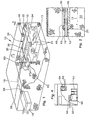
- FIG. 1 an on-site sewage treatment and disposal system 10 in accordance with the present invention.
- the sewage system 10 is for use in areas having a ground water level 12 above a minimum depth below grade, which causes a limiting zone which would otherwise prevent obtaining a permit for installation of a below grade leach field. It will be recognized by those skilled in the art from the present disclosure that the present system 10 can also be used to reduce the required size for a leach field and/or to increase the perc rate of the soil.
- the sewage system 10 preferably includes a septic tank 14 which receives wastewater and sewage from a source such as a house (not shown) through a first pipe 16.
- the septic tank 14 provides for the separation by gravity of gross solids; and also bacteria in the septic tank 14 decomposes and/or digests the raw sewage.
- a fluid or effluent passes by gravity or pumping from the septic tank 14 via a second pipe 18 to a leach field 24.
- a perimeter barrier 20 is arranged around a selected subterraneal volume 22.
- the selected subterraneal volume 22 is of a sufficient size for containing the leach field 24 for the sewage system 10.
- the size for the leach field 24 is usually determined based on regulatory agency requirements, the applicable zoning codes, soil type, and perc rate, etc.
- the perimeter barrier 20 is preferably made of a 30 mil. thick PVC geomembrane and extends to a depth below the minimum required depth for the leach field 24.
- the perimeter barrier 20 may also be made from other materials such as an HDPE geomembrane, or can be formed as a bentonite slurry wall or a soil cement wall.
- the perimeter barrier could be made from any material which creates a barrier around the selected subterraneal volume 22 which is at least partially impermeable to air or gas.
- the preferred PVC geomembrane perimeter barrier 20 is preferably installed around the selected subterraneal volume 22 by excavating a trench around the volume 22, or alternatively by excavating the entire subterraneal volume 22.
- the entire subterraneal volume 22 can be excavated and the soil replaced with a better quality soil for the leach field 24.
- a bentonite slurry wall or soil cement is used to create the perimeter barrier 20, it can also be installed by excavation or by injecting the material into a series of wells located around the selected subterraneal volume 22.
- a drainage pipe 30 adapted to receive fluid is at least partially located within the selected subterraneal volume 22 inside the perimeter barrier 20.
- the drainage pipe 30 comprises a perforated pipe or drain tiles arranged as a conventional leach field having one or more branches 32, 34, 36 which are located entirely within the selected subterraneal volume 22.
- the drainage pipe 30 is placed in a gravel or crushed stone bed 38 and back-filled with soil, and is sized and installed in the same manner as a conventional leach field.
- the drainage pipe 30 and bed 38 refers to any fluid carrying system, such as THE INFILTRATOR® CHAMBER SYSTEM for leach fields, available from INFILTRATOR Systems, Inc., Old Saybrook, Connecticut, such as described in U.S. Patents 5,017,041; 5,156,488 and 5,336,017.
- the second pipe 18 from the septic tank 14 is connected to the drainage pipe 30 for directing effluent from the septic tank 14 to the leach field 24.
- a collar 42 is located around the second pipe 18 where it passes through the perimeter barrier 20 to provide a seal between the second pipe 18 and the perimeter barrier 20.
- the collar 42 is also made of a PVC material and is solvent welded to the perimeter barrier 20 and the second pipe 18.
- the collar 42 can be made of other suitable materials and can be attached to the perimeter barrier 20 and the second pipe 18 in other manners, such as by an adhesive.
- the collar 42 can be omitted, if desired, in order to allow some air exchange between the selected subterraneal volume 22 and the adjacent subterraneal volume.
- an at least partially gas impermeable cap 48 is located over the drainage pipe 30 used for the leach field 24 in the selected subterraneal volume 22.
- the cap 48 is preferably made of the same material as the perimeter barrier 20, as noted above. Fill soil is also preferably located over the cap 48.
- the cap 48 can be made from a variety of other low permeability materials or may omitted, depending on the porosity of the soil.
- a pump 50 having an intake side 52 and a discharge side 54 which discharges gas, which is preferably air, at a pressure greater than atmospheric pressure is provided.
- the pump 50 is located remotely from the selected subterraneal volume 22, such as in the garage or basement of the house connected to the system 10. However, it can be located in an above grade or underground housing located in proximity to the selected subterraneal volume 22.
- the discharge side 54 of the pump 50 is in fluid communication with the selected subterraneal volume 22, preferably via a third pipe 56, to lower the ground water level 12 within the perimeter barrier 20 to a level 13 at or below the minimum depth below grade required for the leach field 24 to operate in its intended manner.
- the pump 50 is a 1/16 horsepower air compressor, such as a Gast Model MOAP101AA.
- a Gast Model MOAP101AA a 1/16 horsepower air compressor
- other types of pumps or compressors could be used, if desired.
- the discharge side 54 of the pump 50 is in fluid communication with the subterraneal volume 22 through the drainage pipe 30.
- the third pipe 56 is preferably used to connect the pump 50 to the drainage pipe 30.
- a level probe 60 which preferably comprises several individual level probes, is positioned within a ground water level monitoring well 62 located within the selected subterraneal volume 22.
- the level probe 60 is in communication with the pump 50, preferably through wires 66 and the controller 64, shown in Figs 3 and 4, which are connected between the level probe 60, the controller 64 and the pump 50, to start and stop the pump 50 based on the ground water level 13 within the perimeter barrier 22 to maintain the ground water 13 within the perimeter barrier 22 at or below the required minimum depth below grade.
- the level probe 60 preferably includes several conductance probes.
- the level controller is a Warrick Series 16M.
- other types of level control devices such as a float actuated switch.
- a septic tank effluent pump 68 is preferably in fluid communication with the drainage pipe 30 via the second pipe 18 to provide a positive pressure on the fluid.
- Effluent pumps are generally known, and the effluent pump 68 used in conjunction with the present invention is the same type used in connection with sand mound leach fields. However, it will be recognized by those skilled in the art from the present disclosure that the effluent pump can be omitted depending on the difference in elevation between the septic tank 14 and the leach field 24 if there is a sufficient head to keep liquid and air from backing up from the drainage pipe 34 to the septic tank 14.
- the system 10 includes means for fresh air exchange with the soil located in the selected subterraneal volume 22.
- the fresh air exchange means is preferably a perforated pipe 72 connected to the monitoring well 62.
- the perforated pipe 72 allows air within the selected subterraneal barrier to exit the area enclosed by the perimeter barrier 20 and the cap 48 through the monitoring well 62 and the perforated pipe 72 into the surrounding soil.
- the air is replaced by fresh air from the pump 50 which is forced into the selected subterraneal volume 22 via the third pipe 56 and the drainage pipes 30. This provides needed oxygen for aerobic organisms located in the soil within the selected subterraneal space 22.
- the fresh air exchange could be provided in other manners, such as a separate pipe from the selected subterraneal volume 22, or a permeable portion located in the perimeter barrier 20 or the cap 48. It will also be recognized by those skilled in the art from the present disclosure that the air exchange system need not be provided if treatment of effluent by anoxic or anaerobic organisms is desired. Without fresh air exchange, organisms which require oxygen will die off and anoxic and/or anaerobic organisms will multiple in numbers. Such systems can be used to treat nitrates in order to prevent them from being discharged into the ground water.
- FIG. 5 a second embodiment of an on-site sewage treatment and disposal system 110 for use in areas having a ground water level above a minimum depth below grade is shown.
- the system 110 in accordance with the second embodiment is similar to the system 10 in accordance with the first preferred embodiment 10 and like elements have been designated with the same reference numerals. The differences between the system 110 in accordance with the second embodiment from the system 10 in accordance with the first embodiment are explained below.
- the system 110 includes a plurality of vertical wells 186 located in the subterraneal volume 22.
- a manifold 188 having an inlet 189 is connected to the wells.
- the inlet 189 is connected to the pump discharge side 54 via the third pipe 56.
- the manifold further includes a plurality of outlets 190 connected to the plurality of wells 186 for discharging gas from the pump 50 at a pressure greater than atmospheric pressure into the selected subterraneal volume 22 to lower the ground water level 13 within the perimeter barrier to a level at or below the minimum required depth below grade in order to allow the leach field 24 to operate in a conventional manner.
- the operation of the first and second systems 10, 110 is similar. Effluent from the septic tank 14 is pumped by effluent pump 68 through the second pipe 18 to the drainage pipe 30 for the leach field 24. The effluent is distributed through the one or more branches 32, 34, 36 of the leach field 24 which are located within the selected subterraneal volume 22 enclosed by the perimeter barrier 20, and preferably by the cap 48.
- the pump 50 provides gas, preferably air, at higher than atmospheric pressure through the third pipe 56 to the drainage lines 30 in the first preferred embodiment of the septic system 10 and through the manifold 188 to the wells 186 in the selective subterraneal volume 22 in the second preferred embodiment 110.
- the air at higher than atmospheric pressure lowers the ground water from the first depth below grade 12 to a level 13 at or below the minimum depth below grade such that the leach field 24 operates in a conventional manner with the required thickness of unsaturated soils within the leach field.
- the effluent pump 68 prevents effluent from being forced back up the second pipe 18 due to the pressure caused by the gas pump 50.
- the effluent in the leach field 24 is absorbed into the earth where additional treatment takes place as the effluent migrates downwardly toward the lowered ground water level 13.
- the level probe 60 located in the monitoring well 62 is connected to the controller 64 to turn the pump 50 on and off in order to maintain sufficient gas pressure within the selective subterraneal volume 22 to maintain the ground water within the perimeter barrier 20 at the level 13 which is at or below the required minimum depth below grade.
- the level probe 60 and/or the controller 64 can be set to turn the pump 50 on when the ground water level 13 within the perimeter barrier 20 reaches the minimum required depth below grade for the leach field 24, and turns the pump 50 off when the ground water level 13 located within the perimeter barrier 20 is lowered by an additional amount such that several hours or more time elapses before the controller 64 cycles the pump on. This should prevent unnecessarily frequent cycling of the pump 50 while maintaining the ground water level 13 within the perimeter barrier 20 at or below the required depth.
- Fresh air exchange in the selected subterraneal volume 22 is preferably provided via the air exchange pipe 72 connected the monitoring well 62 which allows to be forced through the soil into the monitoring well and upwardly to escape through the exchange pipe 72 into the adjacent subterraneal space.
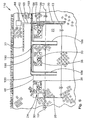
- FIG. 6 a third embodiment of a treatment system 210 in accordance with the present invention is shown.
- the system 210 in accordance with the third embodiment of the invention is similar to the system 10 in accordance with the first embodiment of the invention and like elements have been identified with the same reference numerals.
- sewage from the household flows through the first pipe 16 into the septic tank 14 where the solid matter is separated from liquid and anaerobic bacterial action decomposes the raw sewage.
- Fluid exits the septic tank 14 through the second pipe 18 and is pumped by an effluent pump 68 to the leach field 24 having drainage pipes 30 within the selected subterraneal volume 22.
- a water or treated effluent collection member 214 is located below the selected subterraneal volume 22.
- the collection member is made of 30 mil. thick PVC geomembrane, and is sloped to a collection site 216.
- the effluent collection member 214 may be formed of materials having a sufficient permeability contrast, such as pea gravel over a sand bed, such that the fluid travels through the pea gravel to the collection site 216 instead of migrating downwardly through the sand.
- the collection member 214 is preferably installed by excavating the selected subterraneal volume and installing the 30 mil. thick PVC geomembrane on the bottom.
- the perimeter barrier 20 is also preferably installed prior to back filling with soil. If the soil quality is poor, the soil used to back fill can be augmented with carbon source material, such as peat, or replaced with a better quality soil for the leach field.
- the leach field 24 is then installed in the same manner described in conjunction with the first embodiment.
- An intermediate pipe 218 is connected between the collection site 216 and the inlet of a leach field 224 for a nitrate treatment system 211.
- the nitrate treatment system 211 is identical to the system 10 described above in connection with the first embodiment of the invention except that no fresh air exchange is provided, and includes a perimeter barrier 220 arranged around a second selected subterraneal volume 222, and preferably a cap 248 for reducing the ground water level 12 to a minimum depth below grade.
- the leach field 224 is similar to the leach field 24 in accordance with the first embodiment of the invention and is arranged in a similar manner, and is made from perforated drainage pipe or tiles 230, which is similar to the drainage pipe 30, noted above.
- No fresh air exchange is provided for the nitrate treatment system 211, and the second selected subterraneal volume 222 becomes oxygen depleted, allowing anoxic and/or anaerobic organisms which are used for the treatment of nitrates to thrive.
- Pressurized air is pumped through a pipe 256 into the drainage pipe 230 to lower the ground water level 13 within the perimeter barrier 220 to a level at or below the minimum depth below grade required for the system to operate for nitrate treatment.
- the water level is monitored by a second level control 260 in communication via wires 266 with a second pump, similar to the pump 50.
- the second pump is cycled off and on, in a similar manner to the pump 50, to maintain the ground water level 13 below the minimum required depth below grade.
- ground water level in both enclosed subterraneal volumes 20, 220 can be controlled by a single gas or air pump 50, with both being pressurized at the same time, or controllable valves used to direct the pressurized air flow from the discharge side 54 of the pump 50 to the appropriate subterraneal volume 20, 220.
- pressure in the first selected subterraneal volume 22 will cause the fluid collected by the collection member 214 to flow through the transfer pipe 218 into the leach field 224 of the nitrate treatment system 211.
- a pump (not shown) can be provided in the transfer pipe 218 for transferring fluid to the leach field 224 located within the perimeter barrier 220 surrounding the second selected subterraneal volume 222.
- nitrate treatment system 211 can be used independently of the system 210, if desired, in order to treat nitrates in any water source. It will be similarly recognized that the system 211 can be used for treatment of fluid using other anoxic and/or anaerobic organisms.
Landscapes
- Health & Medical Sciences (AREA)
- Life Sciences & Earth Sciences (AREA)
- Engineering & Computer Science (AREA)
- Hydrology & Water Resources (AREA)
- Public Health (AREA)
- Water Supply & Treatment (AREA)
- Processing Of Solid Wastes (AREA)
- Excavating Of Shafts Or Tunnels (AREA)
- Treatment Of Sludge (AREA)
- Electrical Discharge Machining, Electrochemical Machining, And Combined Machining (AREA)
- Separation Of Suspended Particles By Flocculating Agents (AREA)
Claims (15)
- Système d'épuration et d'évacuation des eaux usées sur place (10) pour des zones dont le niveau de la nappe phréatique (12) est supérieur à une profondeur minimale au-dessous du niveau du sol, comprenant :une barrière périmétrique (20) disposée autour d'un volume souterrain choisi (22) ;une canalisation d'évacuation (30) conçue pour décharger l'effluent des eaux usées jusqu'à un champ de lixiviation des eaux usées (24), le champ de lixiviation des eaux usées (24) étant situé au sein du volume souterrain choisi (22) à l'intérieur de la barrière périmétrique (20) ; une pompe (50) présentant une admission de gaz (52) etun côté de refoulement (54) qui refoule du gaz à une pression supérieure à la pression atmosphérique, le côté de refoulement (54) de la pompe (50) étant en communication fluide avec le volume souterrain choisi (22) pour faire descendre le niveau de la nappe phréatique (12) au sein de la barrière périmétrique (20) jusqu'à un niveau (13) correspondant, ou inférieur à la profondeur minimale au-dessous du niveau du sol.
- Système d'épuration (10) selon la revendication 1, comprenant en outre une chape au moins partiellement imperméable aux gaz (48) située au-dessus de la canalisation d'évacuation (30) dans le volume souterrain choisi (22).
- Système d'épuration (10) selon la revendication 2, comprenant en outre de la terre de remblayage située sur la chape (48).
- Système d'épuration (10) selon la revendication 1, dans lequel le côté de refoulement (54) de la pompe (50) est en communication fluide avec le volume souterrain (22) par l'intermédiaire de la canalisation d'évacuation (30).
- Système d'épuration (10) selon la revendication 1, dans lequel une pluralité de puits (186) sont situés dans le volume souterrain (22), et le système (10) comprend en outre un collecteur (188) comportant une entrée (189) raccordée au côté de refoulement (54) de la pompe et une pluralité de sorties (190) raccordées à la pluralité de puits (186).
- Système d'épuration (10) selon la revendication 1, comprenant en outre une pompe d'effluents de fosse septique (68) en communication fluide avec la canalisation d'évacuation (30) pour appliquer une pression positive sur le fluide.
- Système d'épuration (10) selon la revendication 1, comprenant en outre une sonde de niveau (60) conçue pour être placée dans un puits de surveillance (62) de niveau de la nappe phréatique (12) situé au sein du volume souterrain choisi (22), la sonde de niveau (60) étant en communication avec la pompe (50) pour démarrer et couper l'écoulement de gaz sortant de la pompe (50) en fonction du niveau de la nappe phréatique (12) à l'intérieur de la barrière périmétrique (20) pour maintenir la nappe phréatique (13) à l'intérieur de la barrière périmétrique (20) à ou au-dessous de la profondeur minimale au-dessous du niveau du sol.
- Système d'épuration (10) selon la revendication 6, dans lequel la sonde de niveau (60) est une sonde à conductance.
- Système d'épuration (10) selon la revendication 1, dans lequel la barrière périmétrique (20) comprend un élément parmi une géomembrane à base de PVC, une géomembrane à base de HDPE, une paroi en boue bentonitique, de l'argile, une paroi en sol-ciment et une paroi en coulis chimique.
- Système d'épuration (10) selon la revendication 2, dans lequel la chape (48) comprend un élément parmi une géomembrane à base de PVC, une géomembrane à base de HDPE, une barrière en boue bentonitique, de l'argile, une barrière en sol-ciment et une barrière en coulis chimique.
- Procédé d'évacuation des eaux usées sur place, comprenant les étapes consistant à :(a) choisir un volume souterrain (22) présentant une superficie suffisante pour un champ de lixiviation (24) pour un système septique, le volume souterrain choisi (22) comportant une nappe phréatique située à une première profondeur au-dessous du niveau du sol qui est inférieure à une profondeur minimale requise pour le champ de lixiviation (24) ;(b) disposer un champ de lixiviation (24) pour l'effluent provenant d'un système septique au moins partiellement au sein du volume souterrain choisi (22) ;(c) installer une barrière périmétrique (20) autour du volume souterrain choisi (22) pour isoler le volume souterrain choisi (22) autour du champ de lixiviation (24) des volumes souterrains adjacents (22) ; et(d) faire descendre la nappe phréatique de la première profondeur au-dessous du niveau du sol à un niveau (13) à ou au-dessous de la profondeur minimale au-dessous du niveau du sol en appliquant du gaz à une pression positive ou en pompant la nappe phréatique depuis le volume souterrain choisi (22) ; et(e) maintenir la nappe phréatique à un niveau (13) situé à ou au-dessous de la profondeur minimale au-dessous du niveau du sol, de façon à assurer le fonctionnement traditionnel du champ de lixiviation (24) par application de gaz à une pression positive.
- Procédé selon la revendication 11, dans lequel la barrière périmétrique (20) comporte un bord supérieur et un bord inférieur, le procédé comprenant en outre l'étape consistant à disposer la barrière périmétrique (20) de façon à ce que le bord inférieur se prolonge au-dessous de la deuxième profondeur de la nappe phréatique pour permettre le fonctionnement traditionnel du champ de lixiviation (24) en vue de former un joint hydraulique étanche entre la nappe phréatique et la barrière périmétrique (20).
- Procédé selon la revendication 11, comprenant en outre l'étape consistant à disposer une chape (48) sur le champ de lixiviation (24) dans le volume souterrain (22) pour maintenir la pression positive dans le volume souterrain choisi (22).
- Procédé selon la revendication 11, comprenant en outre les étapes consistant à forer le sol dans ledit volume souterrain choisi (22) pour créer au moins un puits (62) pour appliquer la pression positive sur le volume souterrain (22), et à raccorder un orifice à gaz pour appliquer le gaz à la pression positive dans le puits (62) pour déplacer la nappe phréatique de la profondeur d'origine à la profondeur convenable pour permettre le fonctionnement traditionnel du champ de lixiviation (24).
- Procédé selon la revendication 11, comprenant en outre les étapes consistant à fournir une canalisation (18) pour permettre l'écoulement de l'effluent d'une fosse septique (14) au champ de lixiviation (24) en passant par la barrière périmétrique (20), et à fournir une pression positive sur l'écoulement d'effluent dans la canalisation (18) pour empêcher l'écoulement en retour d'effluent et d'air.
Applications Claiming Priority (3)
| Application Number | Priority Date | Filing Date | Title |
|---|---|---|---|
| US822252 | 1997-03-20 | ||
| US08/822,252 US5827010A (en) | 1997-03-20 | 1997-03-20 | On-site sewage treatment and disposal system |
| PCT/US1998/005426 WO1998041694A1 (fr) | 1997-03-20 | 1998-03-19 | Systeme d'epuration et d'evacuation des eaux usees sur place |
Publications (3)
| Publication Number | Publication Date |
|---|---|
| EP0983403A1 EP0983403A1 (fr) | 2000-03-08 |
| EP0983403A4 EP0983403A4 (fr) | 2002-01-02 |
| EP0983403B1 true EP0983403B1 (fr) | 2005-03-02 |
Family
ID=25235577
Family Applications (1)
| Application Number | Title | Priority Date | Filing Date |
|---|---|---|---|
| EP98911842A Expired - Lifetime EP0983403B1 (fr) | 1997-03-20 | 1998-03-19 | Systeme d'epuration et d'evacuation des eaux usees sur place |
Country Status (8)
| Country | Link |
|---|---|
| US (1) | US5827010A (fr) |
| EP (1) | EP0983403B1 (fr) |
| AT (1) | ATE290131T1 (fr) |
| AU (1) | AU724602B2 (fr) |
| CA (1) | CA2284215C (fr) |
| DE (1) | DE69829180D1 (fr) |
| NZ (1) | NZ338077A (fr) |
| WO (1) | WO1998041694A1 (fr) |
Families Citing this family (17)
| Publication number | Priority date | Publication date | Assignee | Title |
|---|---|---|---|---|
| EP1169270A4 (fr) * | 1999-03-17 | 2004-09-22 | David A Potts | Procede et dispositif pour le traitement de champs d'epandage |
| US7157011B1 (en) | 1999-03-17 | 2007-01-02 | Potts David A | Vent for leach field aeration |
| US20030070985A1 (en) * | 1999-03-17 | 2003-04-17 | Potts David A. | Apparatus for subsurface aerated treatment of wastewater |
| US6444126B1 (en) | 2000-09-19 | 2002-09-03 | T. M. Gates, Inc. | System and method for treating sanitary wastewater for on-site disposal |
| US6726401B1 (en) * | 2001-01-17 | 2004-04-27 | David A. Potts | Treatment of a leach field |
| US6969464B1 (en) * | 2001-01-17 | 2005-11-29 | Potts David A | Dewatering a leach field |
| US6840710B2 (en) | 2001-05-15 | 2005-01-11 | Rar Group, Llc | Underground alluvial water storage reservoir and method |
| CA2499209A1 (fr) * | 2002-09-17 | 2004-04-01 | The White Oak Partnership, L.P. | Systeme de traitement biologique d'eaux usees et procede y relatif |
| US7018075B2 (en) * | 2003-05-02 | 2006-03-28 | Rodgers Holdings | Protective overhead light fixture kit |
| US7192218B2 (en) * | 2004-02-24 | 2007-03-20 | Ps Systems Inc. | Direct recharge injection of underground water reservoirs |
| US7287932B2 (en) * | 2005-08-22 | 2007-10-30 | The English Oak Partnership, L.P. | Ballasting system for on-site sewage treatment and disposal system |
| US20080073087A1 (en) * | 2006-09-26 | 2008-03-27 | Ps Systems Inc. | Ventilation of underground porosity storage reservoirs |
| US8074670B2 (en) * | 2006-09-26 | 2011-12-13 | PS Systems, Inc. | Maintaining dynamic water storage in underground porosity reservoirs |
| US7972080B2 (en) * | 2007-03-14 | 2011-07-05 | PS Systems, Inc. | Bank-sided porosity storage reservoirs |
| US20090173142A1 (en) * | 2007-07-24 | 2009-07-09 | Ps Systems Inc. | Controlling gas pressure in porosity storage reservoirs |
| US10883238B2 (en) * | 2019-03-26 | 2021-01-05 | Edward Goodrich | Groundwater management and redistribution systems, and related methods |
| US12168860B2 (en) | 2022-07-14 | 2024-12-17 | Core Management, LLC | Pneumatic lift and recharge system for horizontal water wells |
Family Cites Families (10)
| Publication number | Priority date | Publication date | Assignee | Title |
|---|---|---|---|---|
| DE3703066A1 (de) * | 1987-02-03 | 1988-08-11 | Holzmann Philipp Ag | Vorrichtung zum verbinden von in eine dichtungswand einzubauenden dichtungsplatten |
| US4850745A (en) * | 1988-06-17 | 1989-07-25 | Sybron Chemicals, Inc. | Bioremediation system |
| US5022786A (en) * | 1990-05-23 | 1991-06-11 | Philo Kenneth W | Method and apparatus for the recovery and treatment of ground water contaminated by hazardous waste |
| US5054961A (en) * | 1990-07-12 | 1991-10-08 | Ocean Todd Enterprises Inc. | Onsite soil treatment process |
| US5246309A (en) * | 1991-05-16 | 1993-09-21 | Hobby Michael M | System and method for decontamination of contaminated ground |
| US5345034A (en) * | 1993-02-03 | 1994-09-06 | The United States Of America As Represented By The United States Department Of Energy | Containment of subsurface contaminants |
| US5435666A (en) * | 1993-12-14 | 1995-07-25 | Environmental Resources Management, Inc. | Methods for isolating a water table and for soil remediation |
| US5382363A (en) * | 1993-12-27 | 1995-01-17 | Boylen; Wilford M. | Septic system and method |
| US5588490A (en) * | 1995-05-31 | 1996-12-31 | Geraghty & Miller, Inc. | Method and system to achieve two dimensional air sparging |
| US5660500A (en) * | 1995-12-15 | 1997-08-26 | Shell Oil Company | Enhanced deep soil vapor extraction process and apparatus utilizing sheet metal pilings |
-
1997
- 1997-03-20 US US08/822,252 patent/US5827010A/en not_active Expired - Lifetime
-
1998
- 1998-03-19 DE DE69829180T patent/DE69829180D1/de not_active Expired - Fee Related
- 1998-03-19 EP EP98911842A patent/EP0983403B1/fr not_active Expired - Lifetime
- 1998-03-19 CA CA002284215A patent/CA2284215C/fr not_active Expired - Fee Related
- 1998-03-19 AU AU65703/98A patent/AU724602B2/en not_active Ceased
- 1998-03-19 WO PCT/US1998/005426 patent/WO1998041694A1/fr not_active Ceased
- 1998-03-19 NZ NZ338077A patent/NZ338077A/en unknown
- 1998-03-19 AT AT98911842T patent/ATE290131T1/de not_active IP Right Cessation
Also Published As
| Publication number | Publication date |
|---|---|
| DE69829180D1 (de) | 2005-04-07 |
| CA2284215A1 (fr) | 1998-09-24 |
| CA2284215C (fr) | 2006-11-28 |
| AU6570398A (en) | 1998-10-12 |
| AU724602B2 (en) | 2000-09-28 |
| EP0983403A1 (fr) | 2000-03-08 |
| US5827010A (en) | 1998-10-27 |
| WO1998041694A1 (fr) | 1998-09-24 |
| EP0983403A4 (fr) | 2002-01-02 |
| NZ338077A (en) | 2001-06-29 |
| ATE290131T1 (de) | 2005-03-15 |
Similar Documents
| Publication | Publication Date | Title |
|---|---|---|
| AU724602B2 (en) | On-site sewage treatment and disposal system | |
| KR100290288B1 (ko) | 잠수역류조를 이용한 침출수차단 시스템 및 방법 | |
| US20110132824A1 (en) | High Performance Sewer System | |
| US20020172559A1 (en) | Underground alluvial water storage reservoir and method | |
| US5895569A (en) | Small bore sewer system | |
| US7022235B2 (en) | Wastewater biological treatment system and method therefor | |
| US9981867B2 (en) | System for enhanced aerobic activity and bio-mat control for onsite wastewater disposal systems | |
| US5099917A (en) | Water well construction | |
| JPS63293224A (ja) | 排水還元井戸 | |
| McCormick | Filter‐Pack Installation and Redevelopment Techniques for Shallow Recharge Shafts a | |
| JP2001170667A (ja) | 敷地内排水処理装置 | |
| JPS61211416A (ja) | 還元井戸工法 | |
| JPS61242216A (ja) | 土木工事における地下水位の低下方法 | |
| US7287932B2 (en) | Ballasting system for on-site sewage treatment and disposal system | |
| Reid | A catalog of water supply and waste disposal methods for individual units | |
| CN1057280C (zh) | 竖井集水回水式氧化塘-土地渗滤场 | |
| JPH0420045B2 (fr) | ||
| Umarov | The Construction and Effectiveness of Combined Drainage Systems | |
| GB2604581A (en) | Water management apparatus | |
| SANIIRI | THE CONSTRUCTION AND EFFECTIVENESS OF COMBINED DRAINAGE SYSTEMS | |
| Pipe | ETI | |
| Swart | STED systems: A low-maintenance sanitation alternative (Part 1) | |
| Trullinger | Water supply, plumbing, and sewage disposal for country homes | |
| JPS6022140B2 (ja) | 排水および雨水の回収方法およびその装置 |
Legal Events
| Date | Code | Title | Description |
|---|---|---|---|
| PUAI | Public reference made under article 153(3) epc to a published international application that has entered the european phase |
Free format text: ORIGINAL CODE: 0009012 |
|
| 17P | Request for examination filed |
Effective date: 19991020 |
|
| AK | Designated contracting states |
Kind code of ref document: A1 Designated state(s): AT BE CH DE DK ES FI FR GB GR IE IT LI LU MC NL PT SE |
|
| A4 | Supplementary search report drawn up and despatched |
Effective date: 20011116 |
|
| AK | Designated contracting states |
Kind code of ref document: A4 Designated state(s): AT BE CH DE DK ES FI FR GB GR IE IT LI LU MC NL PT SE |
|
| 17Q | First examination report despatched |
Effective date: 20020502 |
|
| GRAP | Despatch of communication of intention to grant a patent |
Free format text: ORIGINAL CODE: EPIDOSNIGR1 |
|
| GRAS | Grant fee paid |
Free format text: ORIGINAL CODE: EPIDOSNIGR3 |
|
| GRAA | (expected) grant |
Free format text: ORIGINAL CODE: 0009210 |
|
| AK | Designated contracting states |
Kind code of ref document: B1 Designated state(s): AT BE CH DE DK ES FI FR GB GR IE IT LI LU MC NL PT SE |
|
| PG25 | Lapsed in a contracting state [announced via postgrant information from national office to epo] |
Ref country code: NL Free format text: LAPSE BECAUSE OF FAILURE TO SUBMIT A TRANSLATION OF THE DESCRIPTION OR TO PAY THE FEE WITHIN THE PRESCRIBED TIME-LIMIT Effective date: 20050302 Ref country code: LI Free format text: LAPSE BECAUSE OF FAILURE TO SUBMIT A TRANSLATION OF THE DESCRIPTION OR TO PAY THE FEE WITHIN THE PRESCRIBED TIME-LIMIT Effective date: 20050302 Ref country code: IT Free format text: LAPSE BECAUSE OF FAILURE TO SUBMIT A TRANSLATION OF THE DESCRIPTION OR TO PAY THE FEE WITHIN THE PRE;WARNING: LAPSES OF ITALIAN PATENTS WITH EFFECTIVE DATE BEFORE 2007 MAY HAVE OCCURRED AT ANY TIME BEFORE 2007. THE CORRECT EFFECTIVE DATE MAY BE DIFFERENT FROM THE ONE RECORDED.SCRIBED TIME-LIMIT Effective date: 20050302 Ref country code: FR Free format text: LAPSE BECAUSE OF NON-PAYMENT OF DUE FEES Effective date: 20050302 Ref country code: FI Free format text: LAPSE BECAUSE OF FAILURE TO SUBMIT A TRANSLATION OF THE DESCRIPTION OR TO PAY THE FEE WITHIN THE PRESCRIBED TIME-LIMIT Effective date: 20050302 Ref country code: CH Free format text: LAPSE BECAUSE OF FAILURE TO SUBMIT A TRANSLATION OF THE DESCRIPTION OR TO PAY THE FEE WITHIN THE PRESCRIBED TIME-LIMIT Effective date: 20050302 Ref country code: BE Free format text: LAPSE BECAUSE OF FAILURE TO SUBMIT A TRANSLATION OF THE DESCRIPTION OR TO PAY THE FEE WITHIN THE PRESCRIBED TIME-LIMIT Effective date: 20050302 Ref country code: AT Free format text: LAPSE BECAUSE OF FAILURE TO SUBMIT A TRANSLATION OF THE DESCRIPTION OR TO PAY THE FEE WITHIN THE PRESCRIBED TIME-LIMIT Effective date: 20050302 |
|
| REG | Reference to a national code |
Ref country code: GB Ref legal event code: FG4D |
|
| REG | Reference to a national code |
Ref country code: CH Ref legal event code: EP |
|
| PG25 | Lapsed in a contracting state [announced via postgrant information from national office to epo] |
Ref country code: LU Free format text: LAPSE BECAUSE OF NON-PAYMENT OF DUE FEES Effective date: 20050319 |
|
| PG25 | Lapsed in a contracting state [announced via postgrant information from national office to epo] |
Ref country code: MC Free format text: LAPSE BECAUSE OF NON-PAYMENT OF DUE FEES Effective date: 20050331 |
|
| REG | Reference to a national code |
Ref country code: IE Ref legal event code: FG4D |
|
| REF | Corresponds to: |
Ref document number: 69829180 Country of ref document: DE Date of ref document: 20050407 Kind code of ref document: P |
|
| PG25 | Lapsed in a contracting state [announced via postgrant information from national office to epo] |
Ref country code: GR Free format text: LAPSE BECAUSE OF FAILURE TO SUBMIT A TRANSLATION OF THE DESCRIPTION OR TO PAY THE FEE WITHIN THE PRESCRIBED TIME-LIMIT Effective date: 20050602 Ref country code: DK Free format text: LAPSE BECAUSE OF FAILURE TO SUBMIT A TRANSLATION OF THE DESCRIPTION OR TO PAY THE FEE WITHIN THE PRESCRIBED TIME-LIMIT Effective date: 20050602 |
|
| PG25 | Lapsed in a contracting state [announced via postgrant information from national office to epo] |
Ref country code: ES Free format text: LAPSE BECAUSE OF FAILURE TO SUBMIT A TRANSLATION OF THE DESCRIPTION OR TO PAY THE FEE WITHIN THE PRESCRIBED TIME-LIMIT Effective date: 20050613 |
|
| PG25 | Lapsed in a contracting state [announced via postgrant information from national office to epo] |
Ref country code: PT Free format text: LAPSE BECAUSE OF FAILURE TO SUBMIT A TRANSLATION OF THE DESCRIPTION OR TO PAY THE FEE WITHIN THE PRESCRIBED TIME-LIMIT Effective date: 20050817 |
|
| NLV1 | Nl: lapsed or annulled due to failure to fulfill the requirements of art. 29p and 29m of the patents act | ||
| REG | Reference to a national code |
Ref country code: CH Ref legal event code: PL |
|
| PG25 | Lapsed in a contracting state [announced via postgrant information from national office to epo] |
Ref country code: DE Free format text: LAPSE BECAUSE OF NON-PAYMENT OF DUE FEES Effective date: 20051001 |
|
| PLBE | No opposition filed within time limit |
Free format text: ORIGINAL CODE: 0009261 |
|
| STAA | Information on the status of an ep patent application or granted ep patent |
Free format text: STATUS: NO OPPOSITION FILED WITHIN TIME LIMIT |
|
| 26N | No opposition filed |
Effective date: 20051205 |
|
| EN | Fr: translation not filed | ||
| PGFP | Annual fee paid to national office [announced via postgrant information from national office to epo] |
Ref country code: GB Payment date: 20070327 Year of fee payment: 10 |
|
| PG25 | Lapsed in a contracting state [announced via postgrant information from national office to epo] |
Ref country code: SE Free format text: LAPSE BECAUSE OF FAILURE TO SUBMIT A TRANSLATION OF THE DESCRIPTION OR TO PAY THE FEE WITHIN THE PRESCRIBED TIME-LIMIT Effective date: 20050602 |
|
| GBPC | Gb: european patent ceased through non-payment of renewal fee |
Effective date: 20080319 |
|
| PGFP | Annual fee paid to national office [announced via postgrant information from national office to epo] |
Ref country code: IE Payment date: 20090325 Year of fee payment: 12 |
|
| PG25 | Lapsed in a contracting state [announced via postgrant information from national office to epo] |
Ref country code: GB Free format text: LAPSE BECAUSE OF NON-PAYMENT OF DUE FEES Effective date: 20080319 |
|
| REG | Reference to a national code |
Ref country code: IE Ref legal event code: MM4A |
|
| PG25 | Lapsed in a contracting state [announced via postgrant information from national office to epo] |
Ref country code: IE Free format text: LAPSE BECAUSE OF NON-PAYMENT OF DUE FEES Effective date: 20100319 |