EP0982512B1 - Clutch hydraulic controller - Google Patents
Clutch hydraulic controller Download PDFInfo
- Publication number
- EP0982512B1 EP0982512B1 EP99115519A EP99115519A EP0982512B1 EP 0982512 B1 EP0982512 B1 EP 0982512B1 EP 99115519 A EP99115519 A EP 99115519A EP 99115519 A EP99115519 A EP 99115519A EP 0982512 B1 EP0982512 B1 EP 0982512B1
- Authority
- EP
- European Patent Office
- Prior art keywords
- pressure
- valve
- control
- clutch
- line
- Prior art date
- Legal status (The legal status is an assumption and is not a legal conclusion. Google has not performed a legal analysis and makes no representation as to the accuracy of the status listed.)
- Expired - Lifetime
Links
Images


Classifications
-
- F—MECHANICAL ENGINEERING; LIGHTING; HEATING; WEAPONS; BLASTING
- F16—ENGINEERING ELEMENTS AND UNITS; GENERAL MEASURES FOR PRODUCING AND MAINTAINING EFFECTIVE FUNCTIONING OF MACHINES OR INSTALLATIONS; THERMAL INSULATION IN GENERAL
- F16H—GEARING
- F16H61/00—Control functions within control units of change-speed- or reversing-gearings for conveying rotary motion ; Control of exclusively fluid gearing, friction gearing, gearings with endless flexible members or other particular types of gearing
- F16H61/12—Detecting malfunction or potential malfunction, e.g. fail safe; Circumventing or fixing failures
-
- F—MECHANICAL ENGINEERING; LIGHTING; HEATING; WEAPONS; BLASTING
- F16—ENGINEERING ELEMENTS AND UNITS; GENERAL MEASURES FOR PRODUCING AND MAINTAINING EFFECTIVE FUNCTIONING OF MACHINES OR INSTALLATIONS; THERMAL INSULATION IN GENERAL
- F16H—GEARING
- F16H61/00—Control functions within control units of change-speed- or reversing-gearings for conveying rotary motion ; Control of exclusively fluid gearing, friction gearing, gearings with endless flexible members or other particular types of gearing
- F16H61/0021—Generation or control of line pressure
-
- F—MECHANICAL ENGINEERING; LIGHTING; HEATING; WEAPONS; BLASTING
- F16—ENGINEERING ELEMENTS AND UNITS; GENERAL MEASURES FOR PRODUCING AND MAINTAINING EFFECTIVE FUNCTIONING OF MACHINES OR INSTALLATIONS; THERMAL INSULATION IN GENERAL
- F16H—GEARING
- F16H61/00—Control functions within control units of change-speed- or reversing-gearings for conveying rotary motion ; Control of exclusively fluid gearing, friction gearing, gearings with endless flexible members or other particular types of gearing
- F16H61/02—Control functions within control units of change-speed- or reversing-gearings for conveying rotary motion ; Control of exclusively fluid gearing, friction gearing, gearings with endless flexible members or other particular types of gearing characterised by the signals used
- F16H61/0202—Control functions within control units of change-speed- or reversing-gearings for conveying rotary motion ; Control of exclusively fluid gearing, friction gearing, gearings with endless flexible members or other particular types of gearing characterised by the signals used the signals being electric
- F16H61/0251—Elements specially adapted for electric control units, e.g. valves for converting electrical signals to fluid signals
- F16H2061/0258—Proportional solenoid valve
-
- F—MECHANICAL ENGINEERING; LIGHTING; HEATING; WEAPONS; BLASTING
- F16—ENGINEERING ELEMENTS AND UNITS; GENERAL MEASURES FOR PRODUCING AND MAINTAINING EFFECTIVE FUNCTIONING OF MACHINES OR INSTALLATIONS; THERMAL INSULATION IN GENERAL
- F16H—GEARING
- F16H61/00—Control functions within control units of change-speed- or reversing-gearings for conveying rotary motion ; Control of exclusively fluid gearing, friction gearing, gearings with endless flexible members or other particular types of gearing
- F16H61/12—Detecting malfunction or potential malfunction, e.g. fail safe; Circumventing or fixing failures
- F16H2061/1208—Detecting malfunction or potential malfunction, e.g. fail safe; Circumventing or fixing failures with diagnostic check cycles; Monitoring of failures
-
- F—MECHANICAL ENGINEERING; LIGHTING; HEATING; WEAPONS; BLASTING
- F16—ENGINEERING ELEMENTS AND UNITS; GENERAL MEASURES FOR PRODUCING AND MAINTAINING EFFECTIVE FUNCTIONING OF MACHINES OR INSTALLATIONS; THERMAL INSULATION IN GENERAL
- F16H—GEARING
- F16H61/00—Control functions within control units of change-speed- or reversing-gearings for conveying rotary motion ; Control of exclusively fluid gearing, friction gearing, gearings with endless flexible members or other particular types of gearing
- F16H61/12—Detecting malfunction or potential malfunction, e.g. fail safe; Circumventing or fixing failures
- F16H2061/122—Avoiding failures by using redundant parts
-
- F—MECHANICAL ENGINEERING; LIGHTING; HEATING; WEAPONS; BLASTING
- F16—ENGINEERING ELEMENTS AND UNITS; GENERAL MEASURES FOR PRODUCING AND MAINTAINING EFFECTIVE FUNCTIONING OF MACHINES OR INSTALLATIONS; THERMAL INSULATION IN GENERAL
- F16H—GEARING
- F16H61/00—Control functions within control units of change-speed- or reversing-gearings for conveying rotary motion ; Control of exclusively fluid gearing, friction gearing, gearings with endless flexible members or other particular types of gearing
- F16H61/12—Detecting malfunction or potential malfunction, e.g. fail safe; Circumventing or fixing failures
- F16H2061/1256—Detecting malfunction or potential malfunction, e.g. fail safe; Circumventing or fixing failures characterised by the parts or units where malfunctioning was assumed or detected
- F16H2061/126—Detecting malfunction or potential malfunction, e.g. fail safe; Circumventing or fixing failures characterised by the parts or units where malfunctioning was assumed or detected the failing part is the controller
- F16H2061/1268—Electric parts of the controller, e.g. a defect solenoid, wiring or microprocessor
-
- F—MECHANICAL ENGINEERING; LIGHTING; HEATING; WEAPONS; BLASTING
- F16—ENGINEERING ELEMENTS AND UNITS; GENERAL MEASURES FOR PRODUCING AND MAINTAINING EFFECTIVE FUNCTIONING OF MACHINES OR INSTALLATIONS; THERMAL INSULATION IN GENERAL
- F16H—GEARING
- F16H59/00—Control inputs to control units of change-speed-, or reversing-gearings for conveying rotary motion
- F16H59/36—Inputs being a function of speed
- F16H59/38—Inputs being a function of speed of gearing elements
- F16H59/42—Input shaft speed
-
- F—MECHANICAL ENGINEERING; LIGHTING; HEATING; WEAPONS; BLASTING
- F16—ENGINEERING ELEMENTS AND UNITS; GENERAL MEASURES FOR PRODUCING AND MAINTAINING EFFECTIVE FUNCTIONING OF MACHINES OR INSTALLATIONS; THERMAL INSULATION IN GENERAL
- F16H—GEARING
- F16H61/00—Control functions within control units of change-speed- or reversing-gearings for conveying rotary motion ; Control of exclusively fluid gearing, friction gearing, gearings with endless flexible members or other particular types of gearing
- F16H61/02—Control functions within control units of change-speed- or reversing-gearings for conveying rotary motion ; Control of exclusively fluid gearing, friction gearing, gearings with endless flexible members or other particular types of gearing characterised by the signals used
- F16H61/0262—Control functions within control units of change-speed- or reversing-gearings for conveying rotary motion ; Control of exclusively fluid gearing, friction gearing, gearings with endless flexible members or other particular types of gearing characterised by the signals used the signals being hydraulic
- F16H61/0276—Elements specially adapted for hydraulic control units, e.g. valves
- F16H61/0283—Governor valves
-
- F—MECHANICAL ENGINEERING; LIGHTING; HEATING; WEAPONS; BLASTING
- F16—ENGINEERING ELEMENTS AND UNITS; GENERAL MEASURES FOR PRODUCING AND MAINTAINING EFFECTIVE FUNCTIONING OF MACHINES OR INSTALLATIONS; THERMAL INSULATION IN GENERAL
- F16H—GEARING
- F16H61/00—Control functions within control units of change-speed- or reversing-gearings for conveying rotary motion ; Control of exclusively fluid gearing, friction gearing, gearings with endless flexible members or other particular types of gearing
- F16H61/66—Control functions within control units of change-speed- or reversing-gearings for conveying rotary motion ; Control of exclusively fluid gearing, friction gearing, gearings with endless flexible members or other particular types of gearing specially adapted for continuously variable gearings
- F16H61/662—Control functions within control units of change-speed- or reversing-gearings for conveying rotary motion ; Control of exclusively fluid gearing, friction gearing, gearings with endless flexible members or other particular types of gearing specially adapted for continuously variable gearings with endless flexible members
Definitions
- the present invention relates generally to a hydraulic controller according to the preamble of claim 1 which controls a clutch, and particularly to a hydraulic controller which is used for a vehicular starting clutch.
- This hydraulic controller ensures the movement of the vehicle even while the circuit of the controller is experiencing a breakdown.
- a hydraulic controller of this kind is known from BE-A-100 91 48.
- a pump delivers hydraulic oil to two consecutive valves which set a defined line pressure.
- the line pressure is fed to two parallel solenoid valves which produce a valve control pressure in correspondence to an electrical control signal. From these two solenoids valves the valve control pressure is fed to a further valve, from there to a manually operated valve and from there finally to a hydraulic actuator of the clutch.
- the pressure output by a shift control valve is increased to a maximum, whereby the spool of the further valve and the spool of a pressure switch valve are shifted.
- the pressure of a portion of the conduits is set to a pressure corresponding to the rotational speed of the combustion engine.
- the hydraulic actuator is connected to a pressure that is always present in the conduit system due to the working of the pump.
- the pressure corresponding to the rotational speed of the combustion engine is sent as a signal pressure to a regulating valve for the regulation of the always present pressure. Consequently, also the always present pressure is regulated corresponding to the rotational speed of the combustion engine.
- a vehicular transmission comprises a speed change mechanism and a clutching mechanism (also referred to as "a starting clutch") .
- the speed change mechanism includes an input member, which is driven by an engine, and an output member, which is connected to wheels of a vehicle.
- the starting clutch controls the mechanical power transmission for starting, driving and stopping the vehicle in relation with the engagement and disengagement of the clutch.
- the engagement of the clutch is controlled hydraulically, and in most clutching mechanisms, the hydraulic control fot the operation of the clutch is carried out, for example, in relation to the rotational speed of the engine, which is detected by a sensor, and an electromagnetic valve is actuated in correspondence with the rotational speed detected.
- hydraulic controllers are often equipped with a backup mechanism, in which a signal pressure is generated in correspondence with the rotational speed of the engine, and the hydraulic control is carried out by using this signal pressure.
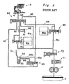
- FIG. 5 shows a starting clutch controller of prior art which uses a pitot tube.
- a pitot flange 51 is provided in a direct connection to the output shaft of the engine, and a pitot tube 53 is provided against the rotational direction in the lubrication oil which accumulates in the oil chamber of the pitot flange 51.
- the pitot tube 53 extracts the dynamic pressure of the lubrication oil, which moves in the pitot flange along with the rotation of the engine, as a signal pressure which corresponds to the rotational speed of the engine.
- this hydraulic circuit used for controlling the starting clutch is described in detail.
- the pressure of the hydraulic oil supplied from a tank T by a pump P is adjusted to a line pressure PL by regulator valves 71 and 72, and this line pressure PL is supplied to a starting clutch control valve 81.
- a control pressure is produced in correspondence with the electrical current applied to the linear solenoid 81 a of this valve.
- This control pressure is supplied through an accumulator 86 and a shift restriction valve 82, which are provided on a line 92 to the starting clutch 5, to control the engagement of the clutch.
- the line pressure PL is also supplied through another line 91c to a shift control valve 85, and a shift control pressure is produced in correspondence with the electrical current applied to the linear solenoid 85a of this valve.
- This shift control pressure is supplied through a line 94 to a shift restriction valve 82 as a signal pressure.
- the shift control pressure is used as the pressure for hydraulic control of the widths of the drive and driven pulleys of the belt- type continuous speed change mechanism, which is not shown in the drawing.
- the shift restriction valve 82 includes a spool 82a, which is biased rightward by a spring 82b, and the shift control pressure creates a thrust which pushes the spool 82a leftward.
- the position of the spool 82a in the shift restriction valve 82 is controllable in correspondence with the magnitude of the shift control pressure, so this pressure is able to control the switching of the circuits for the starting clutch, the adjustment of the valve opening, etc.
- This controller is designed such that if it is determined that there is a breakdown in the circuits of the hydraulic controller, for example, the starting clutch control valve 81 or the electrical circuit breaks down, then the current applied to the shift control valve 85 is turned OFF to fix the shift control valve 85 to its open condition. As a result, the line 94 receives the same line pressure as the line 91.
- FIG. 6 shows all the valves in their breakdown mode.
- the spool 82a of the shift restriction valve 82 is pushed leftward against the spring 82b by the line pressure which is applied through the line 94.
- the line 92 and the line 93 which had been in fluid communication, are now closed to each other while the line 91b and the line 95 are in fluid communication with each other.
- the line pressure in the line 91b acts on a pitot regulator valve 83 through a line 95, and portion of the hydraulic oil is supplied through a line 95b that is branched from the line 95 to an oil supply pipe 52, from which the oil is discharged into the oil chamber of the pitot flange 51.
- the hydraulic oil 54 which accumulates in the oil chamber of the pitot flange 51 is rotated along with the pitot flange 51 in correspondence with its viscosity as the pitot flange 51 is directly connected to the output shaft of the engine.
- the detector portion at the tip of the pitot tube 53 is positioned in this hydraulic oil in the direction against the rotation of the flange.
- the pitot tube 53 detects the dynamic pressure which is proportional to the flow speed of the hydraulic oil, which is rotating.
- the pressure (signal pressure) which corresponds to the rotational speed of the engine is supplied from the pitot tube 53 through a line 96 to the pitot regulator valve 83.
- the pitot regulator valve 83 includes a spool 83a, which is biased leftward in the drawing by a spring 83b, and the above mentioned signal pressure (also referred to as “the pitot pressure” in the following) which corresponds to the rotational speed of the engine generates a thrust rightward for the spool.
- the position of the spool 83a is controlled in correspondence with the rotational speed of the engine. Therefore, the pitot regulator valve 83 regulates the line pressure in the line 95 in correspondence with the pitot pressure, i.e., the signal pressure, and supplies the pressure which corresponds to the rotational speed of the engine, through the lines 97 and 93 to the starting clutch 5.
- the pitot regulator valve 83 substantially closes the fluid communication between the lines 95 and 97 while the rotational speed of the engine is relatively low, for example, when the vehicle is in idling condition. In this condition, the clutch is in the disengaged condition, so the vehicle will not start.
- the rotational speed of the engine is increased a little, i.e., the accelerator pedal is stepped down a little, this valve opens partially, so the vehicle will start gradually.
- the accelerator pedal is stepped further downward to increase the rotational speed of the engine, the clutch is engaged completely, and the vehicle is able to travel continuously.
- the vehicle can start and stop gradually even when the hydraulic controller for the clutch experiences a failure because of, for example, a breakdown in the hydraulic circuit of the hydraulic controller including the starting clutch or a breakdown in the electrical control system.
- the gain adjustment of the clutch control pressure involves the adjustment of not only the spool of the starting clutch control valve 81 but also that of the shift restriction valve 82.
- the gain adjustment of the clutch pressure for the abnormal condition requires the adjustment of the two spools which are in the shift restriction valve 82 and the pitot regulator valve 83. Therefore, a number of man-hours must be spent for adjusting and setting the backup mechanism to keep an appropriate balance in these valves both for the normally operating condition and for the abnormal condition.
- the clutch control pressure which has been already adjusted for controlling the clutch, must pass through an additional valve (e.g., the shift restriction valve 82 in the drawing) in either normal or abnormal condition. Therefore, there is a concern that the existence of such a valve increases the possibility of oil leak and resultant pressure loss especially around this valve and the oil passages connected to it (e.g., the lines 92, 95 and 97).
- this hydraulic circuit of prior art is constructed such that the clutch control pressure, which actuates the starting clutch, passes through the starting clutch control valve 81 (in the normal condition) and the pitot regulator valve 83 (in the abnormal condition).
- the clutch control pressure which actuates the starting clutch
- the pitot regulator valve 83 in the abnormal condition.
- the regulator valve means adjusts and sets a line pressure (PL) which is the original pressure used for control, and the electrically controlled valve produces a valve control pressure in response to an electrical control signal.
- the correspondent pressure generating means produces mechanically a correspondent pressure that corresponds to the rotational speed of the engine, and the clutch pressure control valve adjusts the line pressure by using the valve control pressure or the correspondent pressure and supplies this adjusted line pressure to a hydraulic actuator which actuates the clutch.
- the fault determining means determines whether there is a fault in the hydraulic controller. As long as the hydraulic controller is operating normally, the line pressure is adjusted by the valve control pressure to set the clutch control pressure.
- the line pressure is adjusted by the above mentioned correspondent pressure instead of the valve control pressure to set the clutch control pressure.
- This clutch control pressure is then supplied to the hydraulic actuator of the clutch (e.g., the cylinder chamber 4 of the clutch 5).
- This clutch hydraulic controller controls the clutch pressure control valve by the valve control pressure supplied from the electrically controlled valve in normal operating condition (this "normal operating condition” excludes the condition where the hydraulic controller is experiencing a breakdown. This phrase is used in the following sections to indicate the same meaning defined here) and adjusts and set the line pressure by the clutch pressure control valve to actuate the hydraulic actuator of the clutch.
- the hydraulic controller is determined to be experiencing a breakdown (a failure event)
- the correspondent pressure which is produced by the correspondent pressure generating means and which corresponds to the rotational speed of the engine, instead of the valve control pressure from the electrically controlled valve is supplied to the clutch pressure control valve.
- the clutch pressure control valve is controlled by this pressure, which acts as a signal pressure, and the line pressure is adjusted and set appropriately and supplied to the hydraulic actuator of the clutch. Either in the normal operating condition or in an event of failure, the pressure to the clutch is achieved by adjusting and setting the line pressure with the clutch pressure control valve. Therefore, basically, the above mentioned gain adjustment of the clutch requires only the adjustment of the spool of this clutch pressure control valve. No other adjustment is necessary on the other valves.
- the clutch control pressure which is controlled by this clutch pressure control valve, is supplied directly to the hydraulic actuator of the clutch, so there is no redundant oil supply passages which lead to other valves for this purpose. With a relatively few valves and oil passages, this hydraulic controller performs the hydraulic control at a high accuracy with a relatively small possibility of oil leak and pressure loss.
- the hydraulic circuit of the clutch hydraulic controller is constructed such that the electrically controlled valve and the correspondent pressure generating means are each to provide a signal pressure which controls the valve opening of the clutch pressure control valve, and that each signal pressure is not directly supplied to the clutch as the clutch control pressure.
- This design of the hydraulic controller is advantageous when, for example, the capacity of the clutch must be increased because of an engine replacement for increasing the output power. In this hydraulic controller, simply, the capacity of the clutch pressure control valve, which adjusts the line pressure, should be increased. There is no need to increase the capacities of the electrically controlled valve and the correspondent pressure generating means, and it is not necessary to replace the linear solenoid for a larger power.
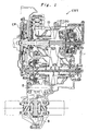
- FIGS. 1 and 2 show the construction of a continuously variable transmission CVT, which is equipped with a hydraulic controller according to the present invention.
- This continuously variable transmission CVT is a belt-type continuously variable transmission which uses a metal V-belt, and it comprises a metal V-belt mechanism 10, which is disposed between the input shaft 1 and the countershaft 2 of the transmission, a planetary gear type forward-reverse selector mechanism 20, which is disposed between the input shaft 1 and the drive pulley 11 of the metal V-belt mechanism 10, and a starting clutch 5, which is disposed between the countershaft 2 and the output member (including a differential mechanism 8) of the transmission.
- This continuously variable transmission CVT is used on a vehicle, so the input shaft 1 is connected through a coupling mechanism CP with the output shaft of the engine ENG, and the power transmitted to the differential mechanism 8 is used for driving the right and left wheels of the vehicle.
- the metal V-belt mechanism 10 comprises the drive pulley 11, which is disposed over the input shaft 1, a driven pulley 16, which is disposed on the countershaft 2, and the metal V-belt 15, which is disposed around these pulleys 11 and 16.
- the drive pulley 11 comprises a stationary pulley half 12, which is disposed rotatably over the input shaft 1, and a movable pulley half 13, which is movable with respect to the stationary pulley half 12 in the axial direction of the pulley 11.
- a drive-side cylinder chamber 14 is defined by a cylinder wall 12a which is fixed to the stationary pulley half 12. The pressure supplied into the cylinder chamber 14 generates a thrust which shifts the movable pulley half 13 in the axial direction of the drive pulley.
- the driven pulley 16 comprises a stationary pulley half 17, which is fixed on the countershaft 2, and a movable pulley half 18, which is movable with respect to the stationary pulley half 17 in the axial direction of the pulley.
- a driven- side cylinder chamber 19 is defined by a cylinder wall 17a which is fixed to the stationary pulley half 17. The pressure supplied into the cylinder chamber 19 generates a thrust which shifts the movable pulley half 18 in the axial direction of the driven pulley.
- the hydraulic pressure which is supplied into these cylinder chambers 14 and 19 is controlled to generate appropriate lateral thrusts in these two pulleys, which thrusts change the widths of the V grooves of the drive and driven pulleys 11 and 16 without any slip of the belt 15 and thereby change the pitch radii of the respective pulleys for the V belt 15 to vary the speed change ratio of the transmission continuously.
- the planetary gear type forward-reverse selector mechanism 20 comprises a double- pinion planetary gear train.
- This planetary gear train comprises a sun gear 21, which is connected to the input shaft 1, a carrier 22, which is connected to the stationary pulley half 12 of the drive pulley 11, and a ring gear 23, which can be held against rotation by a reverse brake 27.
- the planetary gear train also comprises a forward clutch 25, which can connect the sun gear 21 and the ring gear 23. When this forward clutch 25 is engaged, all the gears 21, 22 and 23 rotate together with the input shaft 1 as a one body, and the drive pulley 11 is driven in the same direction as the input shaft 1 (i.e., the forward direction of the vehicle).
- the starting clutch 5 is a clutch which controls the power transmission between the countershaft 2 and the output members of the transmission. When the starting clutch 5 is engaged, it is possible to transmit the power therebetween.
- the pressure supplied to the starting clutch 5 (clutch control pressure) is controlled to adjust the hydraulic engaging force of the clutch so that the torque transmission capacity (torque capacity) between the input side and the output side of the clutch is controllable. Therefore, when the starting clutch 5 is engaged, the output of the engine, after undergoing the speed change by the metal V-belt mechanism 10, is transmitted through gears 6a, 6b, 7a and 7b to the differential mechanism 8 and then divided and transmitted by the differential mechanism 8 to the right and left wheels (not shown). When the starting clutch 5 is released, this power transmission is not carried out, and the transmission is in the neutral condition.
- a hydraulic controller is to control the engagement of the starting clutch 5 by means of a clutch pressure control valve in the normal operating condition as well as in an event of failure.
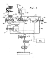
- the construction of this hydraulic controller (also referred to as “the clutch hydraulic controller") is described in reference to FIGS. 3 and 4.
- FIG. 3 shows the whole of the circuit of the clutch hydraulic controller with the respective valves in the normal operating condition while
- FIG. 4 shows the condition of only major valves of the clutch hydraulic controller while the controller is experiencing a breakdown.
- Each "X" mark in the drawings represents a connection to drainage.
- the hydraulic oil which is sucked from a tank T by a pump P is supplied to regulator valves 31 and 32 (regulator valve means), which adjusts the pressure of the oil to a line pressure PL and supplies this pressure to the succeeding lines 61 (61a, 61b and 61c).
- This line pressure is the original control pressure.
- the line pressure PL is supplied through the line 61a to a starting clutch control valve 41, which in turn produces a desired valve control pressure in response to the electrical current applied to the linear solenoid 41a of this valve 41 (controlled by an electrical control signal).
- This valve control pressure is supplied through a line 62a to a clutch pressure control valve 42.
- the clutch pressure control valve 42 includes a spool 42a, which is biased rightward by a spring 42b, and the valve control pressure acts on the spool 42a to produce a leftward thrust.
- the position of the spool 42a is controllable in correspondence to the magnitude of the valve control pressure, which is set by the starting clutch control valve 41.
- the valve opening of the line 61b is controllable as desired for the operation of the transmission, and the line pressure PL is adjusted and then supplied through a line 63 to the clutch 5 for the engagement control of the clutch.
- the starting clutch control valve 41 is controlled by an electrical control signal being output in response to the information provided by a rotational speed detector (not shown), which detects the rotational speed of the input shaft 1 of the transmission. Therefore, the engagement control of the starting clutch is carried out appropriately in correspondence to the rotational speed of the input shaft of the transmission, i.e., the rotational speed of the engine.
- the valve control pressure is also supplied through the line 62b to a shift restriction valve 43.
- the shift restriction valve 43 comprises a spool 43a, which is biased rightward by a spring 43b, and an oil chamber 43c, which accommodates the spring 43b and creates a rightward thrust on the spool when it receives the above mentioned valve control pressure through the line 62b as a control back pressure.
- a shift control valve 45 supplies a desired control pressure into the line 64 when the electrical current applied to the linear solenoid 45a of this valve is controlled appropriately.
- This control pressure is supplied through a line (not shown in the drawing) as a signal pressure to a shift valve, which controls the pressures supplied into the cylinder chambers of the drive and driven pulleys 11 and 16, respectively, for the control of the speed change ratio in the normal operating condition.
- the shift restriction valve 43 is designed such that the spool 43a never shifts leftward as long as it is receiving a range of pressure supplied through the line 64 in the normal operating condition.
- the spool 43a of the shift restriction valve 43 is maintained to the right side because the rightward thrust generated by the spring 43b and by the valve control pressure acting on the spool in the oil chamber 43c overpowers the leftward thrust which is generated by the pressure supplied through the line 64 in the normal operation condition.
- a determining means ECU determines that there is a fault, it turns OFF the electrical currents applied to the starting clutch control valve 41 and to the shift control valve 45.
- This fault determination is carried out for a breakdown in the electrical control system. For example, a failure of the electrical power supply to the electromagnetic valves is determined as a fault. Also, if the real speed change ratio, which is determined from the rotational speeds of the drive and driven pulleys, is not within a predetermined range for the value of the command signal sent to the transmission in the speed change control, then this condition is determined as a fault.
- the determining means ECU which comprises a computer mounted on the vehicle, evaluates in the fault determination such signals as provided by a pressure detector which detects the pressure of each line and a spool position detector which detects the position of the spool in each linear solenoid valve.
- the line 62b is relieved of the pressure while the line 64 receives the line pressure PL.
- the spool 43a of the shift restriction valve 43 is shifted to the left side, and the position of the spool in the valve becomes as shown in FIG. 4.
- the line pressure PL is supplied to a mechanism which comprises a pitot tube.
- the hydraulic oil is supplied through the line 65 to an oil supply pipe 52 and then to a pitot flange 51.
- the pitot flange 51 is directly connected to the output shaft of the engine, the hydraulic oil 54 accumulating in the oil chamber of the flange is drawn and rotated along with the pitot flange 51, which is rotated by the engine, because of the viscosity of the oil.
- the detector portion at the tip of the pitot tube 53 is positioned in the hydraulic oil against the rotational direction of the flange, the pitot tube 53 detects the dynamic pressure which corresponds to the flow speed of the rotating oil.
- a correspondent pressure PD which corresponds to the rotational speed of the engine is sent from the pitot tube 53 through a line 66 to the shift restriction valve 43, not by an electrical means but by this mechanical means, which utilizes the dynamic pressure of the fluid.
- This pressure PD is then supplied as a signal pressure through a line 67 to the clutch pressure control valve 42.
- the clutch pressure control valve 42 includes the spool 42a, which is biased rightward by the spring 42b as mentioned above.
- the position of the spool 42a is controlled by the valve control pressure supplied through the line 62a in the normal operating condition.
- the valve control pressure supplied through the line 62a
- the position of the spool 42a is now controlled by the correspondent pressure PD, which is supplied into the oil chamber 42c of this valve.
- the valve opening between the line 61b and the line 63 is controlled in correspondence to the correspondent pressure PD to adjust the line pressure PL so as to set the clutch control pressure, which is then supplied through the line 63 to the clutch 5.
- the correspondent pressure generating means generates mechanically the pressure (correspondent pressure) which corresponds to the rotational speed of the engine.
- this correspondent pressure is supplied as a signal pressure to the clutch pressure control valve 42 so that the line pressure can be adjusted in correspondence to the rotational speed of the engine for setting the clutch control pressure.
- the correspondent pressure generating means which supplies to the clutch pressure control valve the correspondent pressure that corresponds to the rotational speed of the engine when there is a breakdown, comprises a pitot tube.
- a throttle can be provided on the discharge oil passage of the regulator which produces the line pressure by adjusting the discharge pressure of the oil pump as in the invention described in Japanese Patent Application No. H1O(1998)-57827, which was applied by the same applicant as this patent application. With this throttle, the upstream pressure which corresponds to the rotational speed of the engine is bypassed in the normal operating condition, and when there is a breakdown, by closing the bypass oil passage, this pressure can be drawn and used. In this way, the correspondent pressure generating means can be also realized.
- Line pressure is adjusted by one valve for supplying the pressure to control the engagement of a clutch in normal and abnormal operating conditions.
- the valve control pressure which is controlled by a starting clutch control valve 41 is used for the control of a clutch pressure control valve 42, so the line pressure from a line 61b is adjusted to control the engagement of the starting clutch 5.
- two electrically controlled valves 41 and 45 are turned off, and the line pressure is applied through another line 64.
- the spool of a shift restriction valve 43 is shifted to the left, so the hydraulic oil is supplied to a pitot flange 51.
- the pressure which corresponds to the rotational speed of the engine is supplied as a signal pressure from a pitot pipe 53 through lines 66 and 67 to the shift restriction valve 43.
- This hydraulic controller adjusts the line pressure in the line 61b by using this correspondent pressure for controlling the engagement of the starting clutch 5.
Landscapes
- Engineering & Computer Science (AREA)
- General Engineering & Computer Science (AREA)
- Mechanical Engineering (AREA)
- Control Of Transmission Device (AREA)
- Hydraulic Clutches, Magnetic Clutches, Fluid Clutches, And Fluid Joints (AREA)
Description
- The present invention relates generally to a hydraulic controller according to the preamble of
claim 1 which controls a clutch, and particularly to a hydraulic controller which is used for a vehicular starting clutch. This hydraulic controller ensures the movement of the vehicle even while the circuit of the controller is experiencing a breakdown. - A hydraulic controller of this kind is known from BE-A-100 91 48. In the known hydraulic controller a pump delivers hydraulic oil to two consecutive valves which set a defined line pressure. The line pressure is fed to two parallel solenoid valves which produce a valve control pressure in correspondence to an electrical control signal. From these two solenoids valves the valve control pressure is fed to a further valve, from there to a manually operated valve and from there finally to a hydraulic actuator of the clutch.
- In case of a break-down of the electric system the pressure output by a shift control valve is increased to a maximum, whereby the spool of the further valve and the spool of a pressure switch valve are shifted. By shifting the spool of the pressure switching valve, the pressure of a portion of the conduits is set to a pressure corresponding to the rotational speed of the combustion engine. By shifting the spool of the further valve the hydraulic actuator is connected to a pressure that is always present in the conduit system due to the working of the pump. The pressure corresponding to the rotational speed of the combustion engine is sent as a signal pressure to a regulating valve for the regulation of the always present pressure. Consequently, also the always present pressure is regulated corresponding to the rotational speed of the combustion engine.
- For a better understanding of the present invention some background information is given in the following:
- In general, a vehicular transmission comprises a speed change mechanism and a clutching mechanism (also referred to as "a starting clutch") . The speed change mechanism includes an input member, which is driven by an engine, and an output member, which is connected to wheels of a vehicle. The starting clutch controls the mechanical power transmission for starting, driving and stopping the vehicle in relation with the engagement and disengagement of the clutch. In general, the engagement of the clutch is controlled hydraulically, and in most clutching mechanisms, the hydraulic control fot the operation of the clutch is carried out, for example, in relation to the rotational speed of the engine, which is detected by a sensor, and an electromagnetic valve is actuated in correspondence with the rotational speed detected.
- To avoid a failure in the hydraulic control when an electrical breakdown (e.g., a breakdown of the electrical control system) or an open stick (i.e., the condition where the spool of a valve sticks in its open state) occurs, such hydraulic controllers are often equipped with a backup mechanism, in which a signal pressure is generated in correspondence with the rotational speed of the engine, and the hydraulic control is carried out by using this signal pressure.
- As a backup mechanism, a mechanism which uses a pitot tube is known and described as an example of prior art in Japanese Patent Application No. H1O(1998)-57827, which was applied by the same applicant as this patent application. FIG. 5 shows a starting clutch controller of prior art which uses a pitot tube. In this hydraulic circuit, a
pitot flange 51 is provided in a direct connection to the output shaft of the engine, and apitot tube 53 is provided against the rotational direction in the lubrication oil which accumulates in the oil chamber of thepitot flange 51. Thepitot tube 53 extracts the dynamic pressure of the lubrication oil, which moves in the pitot flange along with the rotation of the engine, as a signal pressure which corresponds to the rotational speed of the engine. In the following paragraph, this hydraulic circuit used for controlling the starting clutch is described in detail. - In this controller, the pressure of the hydraulic oil supplied from a tank T by a pump P is adjusted to a line pressure PL by
regulator valves 71 and 72, and this line pressure PL is supplied to a startingclutch control valve 81. In the starting clutch control valve, a control pressure is produced in correspondence with the electrical current applied to the linear solenoid 81 a of this valve. This control pressure is supplied through anaccumulator 86 and ashift restriction valve 82, which are provided on aline 92 to the startingclutch 5, to control the engagement of the clutch. - On the other hand, the line pressure PL is also supplied through another
line 91c to ashift control valve 85, and a shift control pressure is produced in correspondence with the electrical current applied to thelinear solenoid 85a of this valve. This shift control pressure is supplied through aline 94 to ashift restriction valve 82 as a signal pressure. The shift control pressure is used as the pressure for hydraulic control of the widths of the drive and driven pulleys of the belt- type continuous speed change mechanism, which is not shown in the drawing. - As shown in FIG. 6 in detail, the
shift restriction valve 82 includes aspool 82a, which is biased rightward by aspring 82b, and the shift control pressure creates a thrust which pushes thespool 82a leftward. The position of thespool 82a in theshift restriction valve 82 is controllable in correspondence with the magnitude of the shift control pressure, so this pressure is able to control the switching of the circuits for the starting clutch, the adjustment of the valve opening, etc. - This controller is designed such that if it is determined that there is a breakdown in the circuits of the hydraulic controller, for example, the starting
clutch control valve 81 or the electrical circuit breaks down, then the current applied to theshift control valve 85 is turned OFF to fix theshift control valve 85 to its open condition. As a result, theline 94 receives the same line pressure as the line 91. FIG. 6 shows all the valves in their breakdown mode. - In this mode, the
spool 82a of theshift restriction valve 82 is pushed leftward against thespring 82b by the line pressure which is applied through theline 94. As shown in the drawing, theline 92 and theline 93, which had been in fluid communication, are now closed to each other while the line 91b and theline 95 are in fluid communication with each other. In this condition, the line pressure in the line 91b acts on apitot regulator valve 83 through aline 95, and portion of the hydraulic oil is supplied through aline 95b that is branched from theline 95 to anoil supply pipe 52, from which the oil is discharged into the oil chamber of thepitot flange 51. - The
hydraulic oil 54 which accumulates in the oil chamber of thepitot flange 51 is rotated along with thepitot flange 51 in correspondence with its viscosity as thepitot flange 51 is directly connected to the output shaft of the engine. The detector portion at the tip of thepitot tube 53 is positioned in this hydraulic oil in the direction against the rotation of the flange. Thus, thepitot tube 53 detects the dynamic pressure which is proportional to the flow speed of the hydraulic oil, which is rotating. As a result, the pressure (signal pressure) which corresponds to the rotational speed of the engine is supplied from thepitot tube 53 through aline 96 to thepitot regulator valve 83. - The
pitot regulator valve 83 includes aspool 83a, which is biased leftward in the drawing by aspring 83b, and the above mentioned signal pressure (also referred to as "the pitot pressure" in the following) which corresponds to the rotational speed of the engine generates a thrust rightward for the spool. Thus, the position of thespool 83a is controlled in correspondence with the rotational speed of the engine. Therefore, thepitot regulator valve 83 regulates the line pressure in theline 95 in correspondence with the pitot pressure, i.e., the signal pressure, and supplies the pressure which corresponds to the rotational speed of the engine, through thelines clutch 5. - In this clutch control circuit, the
pitot regulator valve 83 substantially closes the fluid communication between thelines - By the provision of such a backup mechanism, the vehicle can start and stop gradually even when the hydraulic controller for the clutch experiences a failure because of, for example, a breakdown in the hydraulic circuit of the hydraulic controller including the starting clutch or a breakdown in the electrical control system.
- However, in this type of backup mechanism, the gain adjustment of the clutch control pressure (i.e., the adjustment of the clutch control pressure against the signal pressure) involves the adjustment of not only the spool of the starting
clutch control valve 81 but also that of theshift restriction valve 82. Also, the gain adjustment of the clutch pressure for the abnormal condition requires the adjustment of the two spools which are in theshift restriction valve 82 and thepitot regulator valve 83. Therefore, a number of man-hours must be spent for adjusting and setting the backup mechanism to keep an appropriate balance in these valves both for the normally operating condition and for the abnormal condition. - In addition, in this hydraulic circuit, the clutch control pressure, which has been already adjusted for controlling the clutch, must pass through an additional valve (e.g., the
shift restriction valve 82 in the drawing) in either normal or abnormal condition. Therefore, there is a concern that the existence of such a valve increases the possibility of oil leak and resultant pressure loss especially around this valve and the oil passages connected to it (e.g., thelines - Moreover, this hydraulic circuit of prior art is constructed such that the clutch control pressure, which actuates the starting clutch, passes through the starting clutch control valve 81 (in the normal condition) and the pitot regulator valve 83 (in the abnormal condition). As a result, for example, if the engine is replaced with another one which has a larger output power, and therefore the capacity of the clutch must be increased, then these valves must be also replaced to increase the capacities as well as the capacity of the linear solenoid valve 81a. This is another disadvantage.
- The object of the invention is attained by a clutch hydraulic controller having the features of
claim 1. The function of a large part of these features is explained below: - The regulator valve means adjusts and sets a line pressure (PL) which is the original pressure used for control, and the electrically controlled valve produces a valve control pressure in response to an electrical control signal. The correspondent pressure generating means produces mechanically a correspondent pressure that corresponds to the rotational speed of the engine, and the clutch pressure control valve adjusts the line pressure by using the valve control pressure or the correspondent pressure and supplies this adjusted line pressure to a hydraulic actuator which actuates the clutch. The fault determining means determines whether there is a fault in the hydraulic controller. As long as the hydraulic controller is operating normally, the line pressure is adjusted by the valve control pressure to set the clutch control pressure. However, if the determining means determines that there is a breakdown in the hydraulic controller, then the line pressure is adjusted by the above mentioned correspondent pressure instead of the valve control pressure to set the clutch control pressure. This clutch control pressure is then supplied to the hydraulic actuator of the clutch (e.g., the
cylinder chamber 4 of the clutch 5). - This clutch hydraulic controller controls the clutch pressure control valve by the valve control pressure supplied from the electrically controlled valve in normal operating condition (this "normal operating condition" excludes the condition where the hydraulic controller is experiencing a breakdown. This phrase is used in the following sections to indicate the same meaning defined here) and adjusts and set the line pressure by the clutch pressure control valve to actuate the hydraulic actuator of the clutch. However, if the hydraulic controller is determined to be experiencing a breakdown (a failure event), then the correspondent pressure, which is produced by the correspondent pressure generating means and which corresponds to the rotational speed of the engine, instead of the valve control pressure from the electrically controlled valve is supplied to the clutch pressure control valve. Now, the clutch pressure control valve is controlled by this pressure, which acts as a signal pressure, and the line pressure is adjusted and set appropriately and supplied to the hydraulic actuator of the clutch. Either in the normal operating condition or in an event of failure, the pressure to the clutch is achieved by adjusting and setting the line pressure with the clutch pressure control valve. Therefore, basically, the above mentioned gain adjustment of the clutch requires only the adjustment of the spool of this clutch pressure control valve. No other adjustment is necessary on the other valves.
- The clutch control pressure, which is controlled by this clutch pressure control valve, is supplied directly to the hydraulic actuator of the clutch, so there is no redundant oil supply passages which lead to other valves for this purpose. With a relatively few valves and oil passages, this hydraulic controller performs the hydraulic control at a high accuracy with a relatively small possibility of oil leak and pressure loss.
- Furthermore, the hydraulic circuit of the clutch hydraulic controller according to the present invention is constructed such that the electrically controlled valve and the correspondent pressure generating means are each to provide a signal pressure which controls the valve opening of the clutch pressure control valve, and that each signal pressure is not directly supplied to the clutch as the clutch control pressure. This design of the hydraulic controller is advantageous when, for example, the capacity of the clutch must be increased because of an engine replacement for increasing the output power. In this hydraulic controller, simply, the capacity of the clutch pressure control valve, which adjusts the line pressure, should be increased. There is no need to increase the capacities of the electrically controlled valve and the correspondent pressure generating means, and it is not necessary to replace the linear solenoid for a larger power.
- Further scope of applicability of the present invention will become apparent from the detailed description given hereinafter. However, it should be understood that the detailed description and specific examples, while indicating preferred embodiments of the invention, are given by way of illustration only, since various changes and modifications within the spirit and scope of the invention will become apparent to those skilled in the art from this detailed description.
- The present invention will become more fully understood from the detailed description given herein below and the accompanying drawings which are given by way of illustration only and thus are not limitative of the present invention and wherein:
- FIG. 1 is a cross-sectional view showing a continuously variable transmission which is equipped with a hydraulic controller according to the present invention;
- FIG. 2 is a schematic diagram showing the construction of the mechanisms for power transmission of the transmission;
- FIG. 3 is a hydraulic circuit diagram showing the construction of an embodiment of hydraulic controller according to the present invention;
- FIG. 4 is an illustration showing the actuation of respective valves when a major hydraulic circuit constituting the hydraulic controller experiences a breakdown;
- FIG. 5 is a hydraulic circuit diagram showing an example of prior- art hydraulic controller; and
- FIG. 6 is an illustration showing the actuation of respective valves when a major hydraulic circuit constituting the prior-art hydraulic controller experiences a breakdown.
-
- FIGS. 1 and 2 show the construction of a continuously variable transmission CVT, which is equipped with a hydraulic controller according to the present invention. This continuously variable transmission CVT is a belt-type continuously variable transmission which uses a metal V-belt, and it comprises a metal V-
belt mechanism 10, which is disposed between theinput shaft 1 and thecountershaft 2 of the transmission, a planetary gear type forward-reverse selector mechanism 20, which is disposed between theinput shaft 1 and the drive pulley 11 of the metal V-belt mechanism 10, and a startingclutch 5, which is disposed between thecountershaft 2 and the output member (including a differential mechanism 8) of the transmission. This continuously variable transmission CVT is used on a vehicle, so theinput shaft 1 is connected through a coupling mechanism CP with the output shaft of the engine ENG, and the power transmitted to the differential mechanism 8 is used for driving the right and left wheels of the vehicle. - The metal V-
belt mechanism 10 comprises the drive pulley 11, which is disposed over theinput shaft 1, a drivenpulley 16, which is disposed on thecountershaft 2, and the metal V-belt 15, which is disposed around thesepulleys 11 and 16. - The drive pulley 11 comprises a
stationary pulley half 12, which is disposed rotatably over theinput shaft 1, and amovable pulley half 13, which is movable with respect to thestationary pulley half 12 in the axial direction of the pulley 11. On the outside of themovable pulley half 13, a drive-side cylinder chamber 14 is defined by acylinder wall 12a which is fixed to thestationary pulley half 12. The pressure supplied into thecylinder chamber 14 generates a thrust which shifts themovable pulley half 13 in the axial direction of the drive pulley. - The driven
pulley 16 comprises astationary pulley half 17, which is fixed on thecountershaft 2, and amovable pulley half 18, which is movable with respect to thestationary pulley half 17 in the axial direction of the pulley. On the outside of themovable pulley half 18, a driven-side cylinder chamber 19 is defined by acylinder wall 17a which is fixed to thestationary pulley half 17. The pressure supplied into thecylinder chamber 19 generates a thrust which shifts themovable pulley half 18 in the axial direction of the driven pulley. - The hydraulic pressure which is supplied into these
cylinder chambers pulleys 11 and 16 without any slip of thebelt 15 and thereby change the pitch radii of the respective pulleys for theV belt 15 to vary the speed change ratio of the transmission continuously. - The planetary gear type forward-
reverse selector mechanism 20 comprises a double- pinion planetary gear train. This planetary gear train comprises asun gear 21, which is connected to theinput shaft 1, acarrier 22, which is connected to thestationary pulley half 12 of the drive pulley 11, and aring gear 23, which can be held against rotation by areverse brake 27. The planetary gear train also comprises aforward clutch 25, which can connect thesun gear 21 and thering gear 23. When this forward clutch 25 is engaged, all thegears input shaft 1 as a one body, and the drive pulley 11 is driven in the same direction as the input shaft 1 (i.e., the forward direction of the vehicle). On the other hand, if thereverse brake 27 is engaged, thering gear 23 is held stationary, so thecarrier 22 rotates in the direction opposite to that of thesun gear 21, and the drive pulley 11 is driven in the direction opposite to that of the input shaft 1 (i.e., the reverse direction). - The starting
clutch 5 is a clutch which controls the power transmission between thecountershaft 2 and the output members of the transmission. When the startingclutch 5 is engaged, it is possible to transmit the power therebetween. The pressure supplied to the starting clutch 5 (clutch control pressure) is controlled to adjust the hydraulic engaging force of the clutch so that the torque transmission capacity (torque capacity) between the input side and the output side of the clutch is controllable. Therefore, when the startingclutch 5 is engaged, the output of the engine, after undergoing the speed change by the metal V-belt mechanism 10, is transmitted throughgears clutch 5 is released, this power transmission is not carried out, and the transmission is in the neutral condition. - A hydraulic controller according to the present invention is to control the engagement of the starting
clutch 5 by means of a clutch pressure control valve in the normal operating condition as well as in an event of failure. The construction of this hydraulic controller (also referred to as "the clutch hydraulic controller") is described in reference to FIGS. 3 and 4. FIG. 3 shows the whole of the circuit of the clutch hydraulic controller with the respective valves in the normal operating condition while FIG. 4 shows the condition of only major valves of the clutch hydraulic controller while the controller is experiencing a breakdown. Each "X" mark in the drawings represents a connection to drainage. - In this hydraulic controller, as shown in FIG. 3, the hydraulic oil which is sucked from a tank T by a pump P is supplied to
regulator valves 31 and 32 (regulator valve means), which adjusts the pressure of the oil to a line pressure PL and supplies this pressure to the succeeding lines 61 (61a, 61b and 61c). This line pressure is the original control pressure. - The line pressure PL is supplied through the line 61a to a starting
clutch control valve 41, which in turn produces a desired valve control pressure in response to the electrical current applied to thelinear solenoid 41a of this valve 41 (controlled by an electrical control signal). This valve control pressure is supplied through aline 62a to a clutchpressure control valve 42. - The clutch
pressure control valve 42 includes aspool 42a, which is biased rightward by aspring 42b, and the valve control pressure acts on thespool 42a to produce a leftward thrust. As a result, the position of thespool 42a is controllable in correspondence to the magnitude of the valve control pressure, which is set by the startingclutch control valve 41. In this condition, the valve opening of the line 61b is controllable as desired for the operation of the transmission, and the line pressure PL is adjusted and then supplied through aline 63 to theclutch 5 for the engagement control of the clutch. - The starting
clutch control valve 41 is controlled by an electrical control signal being output in response to the information provided by a rotational speed detector (not shown), which detects the rotational speed of theinput shaft 1 of the transmission. Therefore, the engagement control of the starting clutch is carried out appropriately in correspondence to the rotational speed of the input shaft of the transmission, i.e., the rotational speed of the engine. - The valve control pressure is also supplied through the
line 62b to ashift restriction valve 43. Theshift restriction valve 43 comprises aspool 43a, which is biased rightward by aspring 43b, and anoil chamber 43c, which accommodates thespring 43b and creates a rightward thrust on the spool when it receives the above mentioned valve control pressure through theline 62b as a control back pressure. - To the
shift restriction valve 43, the output of ashift control valve 45 is connected through aline 64. Theshift control valve 45 supplies a desired control pressure into theline 64 when the electrical current applied to the linear solenoid 45a of this valve is controlled appropriately. This control pressure is supplied through a line (not shown in the drawing) as a signal pressure to a shift valve, which controls the pressures supplied into the cylinder chambers of the drive and drivenpulleys 11 and 16, respectively, for the control of the speed change ratio in the normal operating condition. Theshift restriction valve 43 is designed such that thespool 43a never shifts leftward as long as it is receiving a range of pressure supplied through theline 64 in the normal operating condition. In other words, thespool 43a of theshift restriction valve 43 is maintained to the right side because the rightward thrust generated by thespring 43b and by the valve control pressure acting on the spool in theoil chamber 43c overpowers the leftward thrust which is generated by the pressure supplied through theline 64 in the normal operation condition. - In this hydraulic control circuit, when a determining means ECU determines that there is a fault, it turns OFF the electrical currents applied to the starting
clutch control valve 41 and to theshift control valve 45. This fault determination is carried out for a breakdown in the electrical control system. For example, a failure of the electrical power supply to the electromagnetic valves is determined as a fault. Also, if the real speed change ratio, which is determined from the rotational speeds of the drive and driven pulleys, is not within a predetermined range for the value of the command signal sent to the transmission in the speed change control, then this condition is determined as a fault. Furthermore, the determining means ECU, which comprises a computer mounted on the vehicle, evaluates in the fault determination such signals as provided by a pressure detector which detects the pressure of each line and a spool position detector which detects the position of the spool in each linear solenoid valve. - Here, the actuation of each valve at the event of such a breakdown is described in reference to FIG. 4. When the electrical current to the starting
clutch control valve 41 is turned OFF, the spool of this valve is shifted to the right side by aspring 41c provided inside the valve. In this condition, the line 61a is closed, and the pressure remaining in the line 62 is purged to the drain X. On the other hand, when the electrical current to theshift control valve 45 is turned OFF, the spool 45b of this valve is shifted to the left side by aspring 45c provided inside the valve. In this condition, the valve opening between thelines 61d and 64 becomes maximum, and the line pressure PL in the line 61d is supplied through theline 64 to a side port of theshift restriction valve 43. - With respect to the
shift restriction valve 43, theline 62b is relieved of the pressure while theline 64 receives the line pressure PL. As a result, thespool 43a of theshift restriction valve 43 is shifted to the left side, and the position of the spool in the valve becomes as shown in FIG. 4. - As the valve is open between the
line 65 and the line 61c, which are charged with the line pressure PL, as shown in the drawing, the line pressure PL is supplied to a mechanism which comprises a pitot tube. In this embodiment, the hydraulic oil is supplied through theline 65 to anoil supply pipe 52 and then to apitot flange 51. As thepitot flange 51 is directly connected to the output shaft of the engine, thehydraulic oil 54 accumulating in the oil chamber of the flange is drawn and rotated along with thepitot flange 51, which is rotated by the engine, because of the viscosity of the oil. As the detector portion at the tip of thepitot tube 53 is positioned in the hydraulic oil against the rotational direction of the flange, thepitot tube 53 detects the dynamic pressure which corresponds to the flow speed of the rotating oil. - In this way, when there is a breakdown in the hydraulic control circuit, a correspondent pressure PD which corresponds to the rotational speed of the engine is sent from the
pitot tube 53 through aline 66 to theshift restriction valve 43, not by an electrical means but by this mechanical means, which utilizes the dynamic pressure of the fluid. This pressure PD is then supplied as a signal pressure through aline 67 to the clutchpressure control valve 42. - The clutch
pressure control valve 42 includes thespool 42a, which is biased rightward by thespring 42b as mentioned above. The position of thespool 42a is controlled by the valve control pressure supplied through theline 62a in the normal operating condition. However, when there is a breakdown, as the valve control pressure is not supplied from theline 62a, the position of thespool 42a is now controlled by the correspondent pressure PD, which is supplied into theoil chamber 42c of this valve. In this way, the valve opening between the line 61b and theline 63 is controlled in correspondence to the correspondent pressure PD to adjust the line pressure PL so as to set the clutch control pressure, which is then supplied through theline 63 to theclutch 5. - In other words, the correspondent pressure generating means generates mechanically the pressure (correspondent pressure) which corresponds to the rotational speed of the engine. When there is a breakdown in the electrical control system or the hydraulic control circuit, this correspondent pressure is supplied as a signal pressure to the clutch
pressure control valve 42 so that the line pressure can be adjusted in correspondence to the rotational speed of the engine for setting the clutch control pressure. - With this hydraulic control circuit, which is designed for controlling the clutch as described above, when there is a breakdown, the clutch engagement control is still carried out in the following manner. When the rotational speed of the engine is relatively low, for example, the vehicle is in idling, the correspondent pressure (pitot pressure) generated is relatively low. In this condition, the valve opening between the line 61b and the
line 63 is relatively small, so the clutch is kept in the disengaged condition, and the vehicle will not start. When the accelerator pedal is stepped down a little to increase the rotational speed of the engine a little, the valve opening increases accordingly, and the clutch is engaged in half way, so the vehicle starts gradually. Furthermore, when the accelerator pedal is stepped down deeply to increase the rotational speed of the engine further, the correspondent pressure (pitot pressure) increases accordingly, and the above mentioned valve opening also increases. In this condition, the clutch is engaged completely, so the vehicle is in the normal driving condition. - In the above embodiment, the correspondent pressure generating means, which supplies to the clutch pressure control valve the correspondent pressure that corresponds to the rotational speed of the engine when there is a breakdown, comprises a pitot tube. This is only an example, and the present invention is not limited to this embodiment. For example, a throttle can be provided on the discharge oil passage of the regulator which produces the line pressure by adjusting the discharge pressure of the oil pump as in the invention described in Japanese Patent Application No. H1O(1998)-57827, which was applied by the same applicant as this patent application. With this throttle, the upstream pressure which corresponds to the rotational speed of the engine is bypassed in the normal operating condition, and when there is a breakdown, by closing the bypass oil passage, this pressure can be drawn and used. In this way, the correspondent pressure generating means can be also realized.
- The invention being thus described, it will be obvious that the same may be varied in many ways. Such variations are not to be regarded as a departure from the scope of the invention, and all such modifications as would be obvious to one skilled in the art are intended to be included within the scope of the following claims.
- Line pressure is adjusted by one valve for supplying the pressure to control the engagement of a clutch in normal and abnormal operating conditions. In the normal operating condition, the valve control pressure which is controlled by a starting
clutch control valve 41 is used for the control of a clutchpressure control valve 42, so the line pressure from a line 61b is adjusted to control the engagement of the startingclutch 5. If there is a breakdown, two electrically controlledvalves line 64. As a result, the spool of ashift restriction valve 43 is shifted to the left, so the hydraulic oil is supplied to apitot flange 51. In this condition, the pressure (correspondent pressure) which corresponds to the rotational speed of the engine is supplied as a signal pressure from apitot pipe 53 throughlines shift restriction valve 43. This hydraulic controller adjusts the line pressure in the line 61b by using this correspondent pressure for controlling the engagement of the startingclutch 5.
Claims (4)
- A clutch hydraulic controller comprising:wherein as long as said fault determining means (ECU) determines that said hydraulic controller is operating normally, said line pressure (PL) is adjusted using said valve control pressure for setting a clutch control pressure; and if said fault determining means (ECU) determines that there is a breakdown, then said line pressure is adjusted using said correspondent pressurea hydraulic actuator for engaging and disengaging a clutch,regulator valve means (31, 32), which adjusts and sets a line pressure (PL), an electrically controlled valve (41), which produces a valve control pressure in correspondence to an electrical control signal; wherein
said electrically controlled valve comprises a linear solenoid valve, and when said electrical control signal is turned off, said valve control pressure becomes nil,
correspondent pressure generating means (51, 52, 53, 54), which produces mechanically a correspondent pressure (PD) that corresponds to rotational speed of an engine,
fault determining means (ECU), which determines existence of a fault, a shift restriction valve (43), which draws selectively either said valve control pressure or said correspondent pressure, wherein a signal pressure is supplied to said shift restriction valve (43) from a shift control valve (45) which comprises a linear solenoid valve (45a) for actuation control, and when electrical current to this linear solenoid valve (45a) is turned off, said signal pressure is supplied at a maximum pressure to said shift restriction valve (43) so that said shift restriction valve (43) selectively draws said correspondent pressure, and
instead of said valve control pressure, for setting said clutch control pressure,
characterized in that said hydraulic controller further comprises:and in thata clutch pressure control valve (42) to which the pressure drawn selectively by said shift restriction valve (43) is supplied and which adjusts said line pressure (PL) by using said valve control pressure or said correspondent pressure and supplies this adjusted line pressure to said hydraulic actuator,
said valve control pressure is supplied to said shift restriction valve (43) for actuation control. - The hydraulic controller as set forth in claim 1, wherein:said correspondent pressure generating means (51, 52, 53, 54) comprises a pitot flange (51), which rotates at identical rotational speed as the engine, and a pitot tube (53), which is provided in said pitot flange (51) and detects dynamic pressure of hydraulic oil in said pitot flange (51), andsaid dynamic pressure is used as said correspondent pressure (PD).
- The hydraulic controller as set forth in claim 1 or 2, wherein:said shift control valve (45) is normally used for speed change control, and pressure used for speed change control is equal to or smaller than said maximum pressure, andwhen said pressure for speed change control is supplied to said shift restriction valve (43), said shift restriction valve (43) selectively draws said valve control pressure and supplies said valve control pressure to said clutch pressure control valve (42).
- The hydraulic controller as set forth in claim 1 or claims 1, 2 and 3, wherein:if said signal pressure is supplied at a maximum pressure to said shift restriction valve (43) because electrical current to said shift control valve (43) is turned off, andif said valve control pressure, which acts on said shift restriction valve (43), is nil because the electrical current to said electrically controlled valve (41) is turned off, thensaid shift restriction valve (43) selectively draws said correspondent pressure, which is then supplied to said clutch pressure control valve (42).
Applications Claiming Priority (2)
| Application Number | Priority Date | Filing Date | Title |
|---|---|---|---|
| JP10239691A JP2994626B1 (en) | 1998-08-26 | 1998-08-26 | Hydraulic control device for clutch |
| JP23969198 | 1998-08-26 |
Publications (3)
| Publication Number | Publication Date |
|---|---|
| EP0982512A2 EP0982512A2 (en) | 2000-03-01 |
| EP0982512A3 EP0982512A3 (en) | 2002-07-10 |
| EP0982512B1 true EP0982512B1 (en) | 2005-06-29 |
Family
ID=17048490
Family Applications (1)
| Application Number | Title | Priority Date | Filing Date |
|---|---|---|---|
| EP99115519A Expired - Lifetime EP0982512B1 (en) | 1998-08-26 | 1999-08-05 | Clutch hydraulic controller |
Country Status (4)
| Country | Link |
|---|---|
| US (1) | US6155396A (en) |
| EP (1) | EP0982512B1 (en) |
| JP (1) | JP2994626B1 (en) |
| DE (1) | DE69925963T2 (en) |
Families Citing this family (22)
| Publication number | Priority date | Publication date | Assignee | Title |
|---|---|---|---|---|
| IT1319470B1 (en) | 2000-05-29 | 2003-10-10 | Lombardini Srl | BELT DRIVE UNIT WITH CONTINUOUS CHANGE IN THE TRANSMISSION REPORT |
| JP3461329B2 (en) * | 2000-07-05 | 2003-10-27 | 本田技研工業株式会社 | Hydraulic control device for continuously variable transmission |
| US6595338B2 (en) | 2001-09-26 | 2003-07-22 | New Venture Gear, Inc. | Torque transfer clutch with linear piston hydraulic clutch actuator |
| JP2003120804A (en) * | 2001-10-09 | 2003-04-23 | Toyota Motor Corp | Controller for driving mechanism including continuously variable transmission |
| US6974009B2 (en) * | 2002-02-04 | 2005-12-13 | Toyota Jidosha Kabushiki Kaisha | Control apparatus for power train including continuously variable transmission |
| US7128688B2 (en) * | 2003-04-25 | 2006-10-31 | Jatco Ltd | Hydraulic control for automatic transmission |
| US6913554B2 (en) * | 2003-10-03 | 2005-07-05 | Gilbert W. Younger | Methods and systems for improving the operation of transmissions for motor vehicles |
| DE102004020569A1 (en) | 2004-04-27 | 2005-12-01 | Zf Friedrichshafen Ag | Control valve arrangement for controlling a starting clutch of an automatic transmission |
| KR101013947B1 (en) * | 2004-08-30 | 2011-02-14 | 현대자동차주식회사 | Hydraulic control system of continuously variable transmission |
| WO2006110946A1 (en) * | 2005-04-18 | 2006-10-26 | Nt Consulting International Pty Limited | Fluid flow control apparatus and valve system |
| DE102005050493A1 (en) | 2005-10-21 | 2007-04-26 | Zf Friedrichshafen Ag | Control valve arrangement for controlling a starting clutch of an automatic transmission |
| DE102005050494A1 (en) * | 2005-10-21 | 2007-04-26 | Zf Friedrichshafen Ag | Valve arrangement for control of starting clutch of automatic transmission unit, comprises self-holding valve transmitting activating pressure in relation to engine dependant control pressure to activating valve |
| DE102005050489A1 (en) | 2005-10-21 | 2007-04-26 | Zf Friedrichshafen Ag | Control valve arrangement for controlling a starting clutch of an automatic transmission |
| JP4333784B2 (en) * | 2007-07-27 | 2009-09-16 | トヨタ自動車株式会社 | Failure determination device and failure determination method for continuously variable transmission |
| DE102007055811A1 (en) | 2007-12-14 | 2009-06-25 | Zf Friedrichshafen Ag | Hydraulic control arrangement for friction clutch utilized as e.g. moving off clutch, in reduction gear in motor vehicle, has holding valve to which system pressure is supplied, where pressure is activated in terms of adjustment of valve |
| US8425378B2 (en) * | 2009-05-29 | 2013-04-23 | GM Global Technology Operations LLC | Dual gain clutch control system |
| JP4922422B2 (en) * | 2010-02-24 | 2012-04-25 | 本田技研工業株式会社 | Fault detection device in hydraulic circuit of transmission |
| DE102016214378A1 (en) * | 2016-08-03 | 2018-02-08 | Audi Ag | Hydraulic system for an automatic transmission of a motor vehicle |
| US10801612B1 (en) | 2019-04-26 | 2020-10-13 | Caterpillar Inc. | Machine transmission with clutch element hydraulic control |
| US11543006B2 (en) | 2019-06-21 | 2023-01-03 | Team Industries, Inc. | Variable torque limiting clutch for a steel belt continuously variable transmission |
| US11499608B2 (en) * | 2019-06-21 | 2022-11-15 | Team Industries, Inc. | Integrated launch clutch and drive sheave for steel belt continuously variable transmission |
| DE102021208816A1 (en) | 2021-08-12 | 2023-02-16 | Zf Friedrichshafen Ag | Actuation of a converter lock-up clutch of a hydrodynamic torque converter using a safety function |
Family Cites Families (11)
| Publication number | Priority date | Publication date | Assignee | Title |
|---|---|---|---|---|
| JPH01295067A (en) * | 1988-05-19 | 1989-11-28 | Mazda Motor Corp | Hydraulic control device for continuously variable transmission |
| JP2937268B2 (en) * | 1991-01-22 | 1999-08-23 | 本田技研工業株式会社 | Control device for belt type continuously variable transmission |
| GB9111387D0 (en) * | 1991-05-25 | 1991-07-17 | Massey Ferguson Services Nv | Clutches |
| JP2587774B2 (en) * | 1993-04-21 | 1997-03-05 | 本田技研工業株式会社 | Control device for belt type continuously variable transmission |
| DE4340431A1 (en) * | 1993-11-27 | 1995-06-01 | Bosch Gmbh Robert | Electrohydraulic transmission control |
| DE4424790A1 (en) * | 1994-07-14 | 1996-01-18 | Bosch Gmbh Robert | Hydraulic emergency control for a friction clutch arranged between an internal combustion engine and a transmission |
| DE4436506A1 (en) * | 1994-10-13 | 1996-04-18 | Zahnradfabrik Friedrichshafen | Device for controlling a CVT |
| BE1009148A3 (en) * | 1995-02-21 | 1996-12-03 | Vcst Nv | Method for regulating a transmission unit for motor vehicles in failsafe mode and a transmission unit made according to this method |
| DE19519162A1 (en) * | 1995-05-24 | 1996-11-28 | Bosch Gmbh Robert | Hydraulic emergency control for a transmission-dependent change of the hydraulic oil pressures in the hydraulic conical pulley axial adjustments of a continuously variable belt transmission |
| JPH1057827A (en) | 1996-08-19 | 1998-03-03 | Shinya Suzuki | Method and device for milling |
| JPH10239691A (en) | 1997-02-24 | 1998-09-11 | Hitachi Ltd | Method for forming liquid crystal alignment layer |
-
1998
- 1998-08-26 JP JP10239691A patent/JP2994626B1/en not_active Expired - Fee Related
-
1999
- 1999-08-05 EP EP99115519A patent/EP0982512B1/en not_active Expired - Lifetime
- 1999-08-05 DE DE69925963T patent/DE69925963T2/en not_active Expired - Fee Related
- 1999-08-17 US US09/375,380 patent/US6155396A/en not_active Expired - Lifetime
Also Published As
| Publication number | Publication date |
|---|---|
| DE69925963T2 (en) | 2005-12-22 |
| DE69925963D1 (en) | 2005-08-04 |
| JP2994626B1 (en) | 1999-12-27 |
| US6155396A (en) | 2000-12-05 |
| JP2000074205A (en) | 2000-03-14 |
| EP0982512A2 (en) | 2000-03-01 |
| EP0982512A3 (en) | 2002-07-10 |
Similar Documents
| Publication | Publication Date | Title |
|---|---|---|
| EP0982512B1 (en) | Clutch hydraulic controller | |
| US7575111B2 (en) | Hydraulic pressure control apparatus for a vehicular power transmitting device | |
| KR100568047B1 (en) | Hydraulic control device for belt type continuously variable transmission | |
| EP0061735B1 (en) | Apparatus for controlling continuously variable v-belt transmission | |
| US5183439A (en) | Control system for continuously variable transmission | |
| US6835147B2 (en) | Hydraulic pressure controller for automatic transmission | |
| US7179196B2 (en) | Input torque control system of belt-type continuously variable transmission for vehicle | |
| JP2587774B2 (en) | Control device for belt type continuously variable transmission | |
| JP4289407B2 (en) | Hydraulic supply device | |
| JPH04249664A (en) | Hydraulic controller for belt type continuously variable transmission for vehicle | |
| US5674150A (en) | Control apparatus for transmission | |
| US5649876A (en) | Pulley thrust pressure control apparatus for belt-type continuously variable transmission | |
| KR20010019805A (en) | Hydraulic control system of continuously variable transmission for vehicle | |
| EP0942202B1 (en) | Hydraulic circuit for transmission | |
| EP0762018B1 (en) | Hydraulic control apparatus for continuously variable transmission of vehicle | |
| JP3116666B2 (en) | Transmission control device for continuously variable transmission for vehicles | |
| JP2006153104A (en) | Hydraulic controller | |
| US7029409B2 (en) | Hydraulic system for a CVT-transmission of a vehicle | |
| JPH09105457A (en) | Controller for continuously variable transmission | |
| KR100279428B1 (en) | Hydraulic control system of continuously variable transmission for automobile | |
| JP2009250304A (en) | Hydraulic control device | |
| JP2792370B2 (en) | Hydraulic control device for continuously variable transmission | |
| JP3916181B2 (en) | Hydraulic clutch control device for transmission | |
| JP2021116849A (en) | Hydraulic control device | |
| JPH10141458A (en) | Continuously variable transmission controller |
Legal Events
| Date | Code | Title | Description |
|---|---|---|---|
| PUAI | Public reference made under article 153(3) epc to a published international application that has entered the european phase |
Free format text: ORIGINAL CODE: 0009012 |
|
| AK | Designated contracting states |
Kind code of ref document: A2 Designated state(s): AT BE CH CY DE DK ES FI FR GB GR IE IT LI LU MC NL PT SE |
|
| AX | Request for extension of the european patent |
Free format text: AL;LT;LV;MK;RO;SI |
|
| PUAL | Search report despatched |
Free format text: ORIGINAL CODE: 0009013 |
|
| AK | Designated contracting states |
Kind code of ref document: A3 Designated state(s): AT BE CH CY DE DK ES FI FR GB GR IE IT LI LU MC NL PT SE |
|
| AX | Request for extension of the european patent |
Free format text: AL;LT;LV;MK;RO;SI |
|
| 17P | Request for examination filed |
Effective date: 20020820 |
|
| AKX | Designation fees paid |
Designated state(s): DE GB |
|
| 17Q | First examination report despatched |
Effective date: 20030307 |
|
| GRAP | Despatch of communication of intention to grant a patent |
Free format text: ORIGINAL CODE: EPIDOSNIGR1 |
|
| GRAS | Grant fee paid |
Free format text: ORIGINAL CODE: EPIDOSNIGR3 |
|
| GRAA | (expected) grant |
Free format text: ORIGINAL CODE: 0009210 |
|
| AK | Designated contracting states |
Kind code of ref document: B1 Designated state(s): DE GB |
|
| REG | Reference to a national code |
Ref country code: GB Ref legal event code: FG4D |
|
| REF | Corresponds to: |
Ref document number: 69925963 Country of ref document: DE Date of ref document: 20050804 Kind code of ref document: P |
|
| PLBE | No opposition filed within time limit |
Free format text: ORIGINAL CODE: 0009261 |
|
| STAA | Information on the status of an ep patent application or granted ep patent |
Free format text: STATUS: NO OPPOSITION FILED WITHIN TIME LIMIT |
|
| 26N | No opposition filed |
Effective date: 20060330 |
|
| PGFP | Annual fee paid to national office [announced via postgrant information from national office to epo] |
Ref country code: GB Payment date: 20060802 Year of fee payment: 8 |
|
| GBPC | Gb: european patent ceased through non-payment of renewal fee |
Effective date: 20070805 |
|
| PGFP | Annual fee paid to national office [announced via postgrant information from national office to epo] |
Ref country code: DE Payment date: 20080821 Year of fee payment: 10 |
|
| PG25 | Lapsed in a contracting state [announced via postgrant information from national office to epo] |
Ref country code: GB Free format text: LAPSE BECAUSE OF NON-PAYMENT OF DUE FEES Effective date: 20070805 |
|
| PG25 | Lapsed in a contracting state [announced via postgrant information from national office to epo] |
Ref country code: DE Free format text: LAPSE BECAUSE OF NON-PAYMENT OF DUE FEES Effective date: 20100302 |