EP0982176B1 - Système d'alimentation d'un véhicule à traction électrique - Google Patents
Système d'alimentation d'un véhicule à traction électrique Download PDFInfo
- Publication number
- EP0982176B1 EP0982176B1 EP99402060A EP99402060A EP0982176B1 EP 0982176 B1 EP0982176 B1 EP 0982176B1 EP 99402060 A EP99402060 A EP 99402060A EP 99402060 A EP99402060 A EP 99402060A EP 0982176 B1 EP0982176 B1 EP 0982176B1
- Authority
- EP
- European Patent Office
- Prior art keywords
- vehicle
- traction
- energy
- kinetically
- storing energy
- Prior art date
- Legal status (The legal status is an assumption and is not a legal conclusion. Google has not performed a legal analysis and makes no representation as to the accuracy of the status listed.)
- Expired - Lifetime
Links
Images

Classifications
-
- B—PERFORMING OPERATIONS; TRANSPORTING
- B60—VEHICLES IN GENERAL
- B60L—PROPULSION OF ELECTRICALLY-PROPELLED VEHICLES; SUPPLYING ELECTRIC POWER FOR AUXILIARY EQUIPMENT OF ELECTRICALLY-PROPELLED VEHICLES; ELECTRODYNAMIC BRAKE SYSTEMS FOR VEHICLES IN GENERAL; MAGNETIC SUSPENSION OR LEVITATION FOR VEHICLES; MONITORING OPERATING VARIABLES OF ELECTRICALLY-PROPELLED VEHICLES; ELECTRIC SAFETY DEVICES FOR ELECTRICALLY-PROPELLED VEHICLES
- B60L5/00—Current collectors for power supply lines of electrically-propelled vehicles
- B60L5/42—Current collectors for power supply lines of electrically-propelled vehicles for collecting current from individual contact pieces connected to the power supply line
-
- B—PERFORMING OPERATIONS; TRANSPORTING
- B60—VEHICLES IN GENERAL
- B60L—PROPULSION OF ELECTRICALLY-PROPELLED VEHICLES; SUPPLYING ELECTRIC POWER FOR AUXILIARY EQUIPMENT OF ELECTRICALLY-PROPELLED VEHICLES; ELECTRODYNAMIC BRAKE SYSTEMS FOR VEHICLES IN GENERAL; MAGNETIC SUSPENSION OR LEVITATION FOR VEHICLES; MONITORING OPERATING VARIABLES OF ELECTRICALLY-PROPELLED VEHICLES; ELECTRIC SAFETY DEVICES FOR ELECTRICALLY-PROPELLED VEHICLES
- B60L50/00—Electric propulsion with power supplied within the vehicle
- B60L50/30—Electric propulsion with power supplied within the vehicle using propulsion power stored mechanically, e.g. in fly-wheels
-
- B—PERFORMING OPERATIONS; TRANSPORTING
- B60—VEHICLES IN GENERAL
- B60L—PROPULSION OF ELECTRICALLY-PROPELLED VEHICLES; SUPPLYING ELECTRIC POWER FOR AUXILIARY EQUIPMENT OF ELECTRICALLY-PROPELLED VEHICLES; ELECTRODYNAMIC BRAKE SYSTEMS FOR VEHICLES IN GENERAL; MAGNETIC SUSPENSION OR LEVITATION FOR VEHICLES; MONITORING OPERATING VARIABLES OF ELECTRICALLY-PROPELLED VEHICLES; ELECTRIC SAFETY DEVICES FOR ELECTRICALLY-PROPELLED VEHICLES
- B60L50/00—Electric propulsion with power supplied within the vehicle
- B60L50/50—Electric propulsion with power supplied within the vehicle using propulsion power supplied by batteries or fuel cells
- B60L50/51—Electric propulsion with power supplied within the vehicle using propulsion power supplied by batteries or fuel cells characterised by AC-motors
-
- B—PERFORMING OPERATIONS; TRANSPORTING
- B60—VEHICLES IN GENERAL
- B60L—PROPULSION OF ELECTRICALLY-PROPELLED VEHICLES; SUPPLYING ELECTRIC POWER FOR AUXILIARY EQUIPMENT OF ELECTRICALLY-PROPELLED VEHICLES; ELECTRODYNAMIC BRAKE SYSTEMS FOR VEHICLES IN GENERAL; MAGNETIC SUSPENSION OR LEVITATION FOR VEHICLES; MONITORING OPERATING VARIABLES OF ELECTRICALLY-PROPELLED VEHICLES; ELECTRIC SAFETY DEVICES FOR ELECTRICALLY-PROPELLED VEHICLES
- B60L53/00—Methods of charging batteries, specially adapted for electric vehicles; Charging stations or on-board charging equipment therefor; Exchange of energy storage elements in electric vehicles
- B60L53/30—Constructional details of charging stations
- B60L53/32—Constructional details of charging stations by charging in short intervals along the itinerary, e.g. during short stops
-
- B—PERFORMING OPERATIONS; TRANSPORTING
- B60—VEHICLES IN GENERAL
- B60L—PROPULSION OF ELECTRICALLY-PROPELLED VEHICLES; SUPPLYING ELECTRIC POWER FOR AUXILIARY EQUIPMENT OF ELECTRICALLY-PROPELLED VEHICLES; ELECTRODYNAMIC BRAKE SYSTEMS FOR VEHICLES IN GENERAL; MAGNETIC SUSPENSION OR LEVITATION FOR VEHICLES; MONITORING OPERATING VARIABLES OF ELECTRICALLY-PROPELLED VEHICLES; ELECTRIC SAFETY DEVICES FOR ELECTRICALLY-PROPELLED VEHICLES
- B60L7/00—Electrodynamic brake systems for vehicles in general
- B60L7/02—Dynamic electric resistor braking
- B60L7/06—Dynamic electric resistor braking for vehicles propelled by ac motors
-
- B—PERFORMING OPERATIONS; TRANSPORTING
- B60—VEHICLES IN GENERAL
- B60L—PROPULSION OF ELECTRICALLY-PROPELLED VEHICLES; SUPPLYING ELECTRIC POWER FOR AUXILIARY EQUIPMENT OF ELECTRICALLY-PROPELLED VEHICLES; ELECTRODYNAMIC BRAKE SYSTEMS FOR VEHICLES IN GENERAL; MAGNETIC SUSPENSION OR LEVITATION FOR VEHICLES; MONITORING OPERATING VARIABLES OF ELECTRICALLY-PROPELLED VEHICLES; ELECTRIC SAFETY DEVICES FOR ELECTRICALLY-PROPELLED VEHICLES
- B60L9/00—Electric propulsion with power supply external to the vehicle
- B60L9/16—Electric propulsion with power supply external to the vehicle using ac induction motors
- B60L9/24—Electric propulsion with power supply external to the vehicle using ac induction motors fed from ac supply lines
-
- B—PERFORMING OPERATIONS; TRANSPORTING
- B60—VEHICLES IN GENERAL
- B60L—PROPULSION OF ELECTRICALLY-PROPELLED VEHICLES; SUPPLYING ELECTRIC POWER FOR AUXILIARY EQUIPMENT OF ELECTRICALLY-PROPELLED VEHICLES; ELECTRODYNAMIC BRAKE SYSTEMS FOR VEHICLES IN GENERAL; MAGNETIC SUSPENSION OR LEVITATION FOR VEHICLES; MONITORING OPERATING VARIABLES OF ELECTRICALLY-PROPELLED VEHICLES; ELECTRIC SAFETY DEVICES FOR ELECTRICALLY-PROPELLED VEHICLES
- B60L2200/00—Type of vehicles
- B60L2200/26—Rail vehicles
-
- Y—GENERAL TAGGING OF NEW TECHNOLOGICAL DEVELOPMENTS; GENERAL TAGGING OF CROSS-SECTIONAL TECHNOLOGIES SPANNING OVER SEVERAL SECTIONS OF THE IPC; TECHNICAL SUBJECTS COVERED BY FORMER USPC CROSS-REFERENCE ART COLLECTIONS [XRACs] AND DIGESTS
- Y02—TECHNOLOGIES OR APPLICATIONS FOR MITIGATION OR ADAPTATION AGAINST CLIMATE CHANGE
- Y02E—REDUCTION OF GREENHOUSE GAS [GHG] EMISSIONS, RELATED TO ENERGY GENERATION, TRANSMISSION OR DISTRIBUTION
- Y02E60/00—Enabling technologies; Technologies with a potential or indirect contribution to GHG emissions mitigation
- Y02E60/16—Mechanical energy storage, e.g. flywheels or pressurised fluids
-
- Y—GENERAL TAGGING OF NEW TECHNOLOGICAL DEVELOPMENTS; GENERAL TAGGING OF CROSS-SECTIONAL TECHNOLOGIES SPANNING OVER SEVERAL SECTIONS OF THE IPC; TECHNICAL SUBJECTS COVERED BY FORMER USPC CROSS-REFERENCE ART COLLECTIONS [XRACs] AND DIGESTS
- Y02—TECHNOLOGIES OR APPLICATIONS FOR MITIGATION OR ADAPTATION AGAINST CLIMATE CHANGE
- Y02T—CLIMATE CHANGE MITIGATION TECHNOLOGIES RELATED TO TRANSPORTATION
- Y02T10/00—Road transport of goods or passengers
- Y02T10/60—Other road transportation technologies with climate change mitigation effect
- Y02T10/64—Electric machine technologies in electromobility
-
- Y—GENERAL TAGGING OF NEW TECHNOLOGICAL DEVELOPMENTS; GENERAL TAGGING OF CROSS-SECTIONAL TECHNOLOGIES SPANNING OVER SEVERAL SECTIONS OF THE IPC; TECHNICAL SUBJECTS COVERED BY FORMER USPC CROSS-REFERENCE ART COLLECTIONS [XRACs] AND DIGESTS
- Y02—TECHNOLOGIES OR APPLICATIONS FOR MITIGATION OR ADAPTATION AGAINST CLIMATE CHANGE
- Y02T—CLIMATE CHANGE MITIGATION TECHNOLOGIES RELATED TO TRANSPORTATION
- Y02T10/00—Road transport of goods or passengers
- Y02T10/60—Other road transportation technologies with climate change mitigation effect
- Y02T10/70—Energy storage systems for electromobility, e.g. batteries
-
- Y—GENERAL TAGGING OF NEW TECHNOLOGICAL DEVELOPMENTS; GENERAL TAGGING OF CROSS-SECTIONAL TECHNOLOGIES SPANNING OVER SEVERAL SECTIONS OF THE IPC; TECHNICAL SUBJECTS COVERED BY FORMER USPC CROSS-REFERENCE ART COLLECTIONS [XRACs] AND DIGESTS
- Y02—TECHNOLOGIES OR APPLICATIONS FOR MITIGATION OR ADAPTATION AGAINST CLIMATE CHANGE
- Y02T—CLIMATE CHANGE MITIGATION TECHNOLOGIES RELATED TO TRANSPORTATION
- Y02T10/00—Road transport of goods or passengers
- Y02T10/60—Other road transportation technologies with climate change mitigation effect
- Y02T10/7072—Electromobility specific charging systems or methods for batteries, ultracapacitors, supercapacitors or double-layer capacitors
-
- Y—GENERAL TAGGING OF NEW TECHNOLOGICAL DEVELOPMENTS; GENERAL TAGGING OF CROSS-SECTIONAL TECHNOLOGIES SPANNING OVER SEVERAL SECTIONS OF THE IPC; TECHNICAL SUBJECTS COVERED BY FORMER USPC CROSS-REFERENCE ART COLLECTIONS [XRACs] AND DIGESTS
- Y02—TECHNOLOGIES OR APPLICATIONS FOR MITIGATION OR ADAPTATION AGAINST CLIMATE CHANGE
- Y02T—CLIMATE CHANGE MITIGATION TECHNOLOGIES RELATED TO TRANSPORTATION
- Y02T90/00—Enabling technologies or technologies with a potential or indirect contribution to GHG emissions mitigation
- Y02T90/10—Technologies relating to charging of electric vehicles
- Y02T90/12—Electric charging stations
-
- Y—GENERAL TAGGING OF NEW TECHNOLOGICAL DEVELOPMENTS; GENERAL TAGGING OF CROSS-SECTIONAL TECHNOLOGIES SPANNING OVER SEVERAL SECTIONS OF THE IPC; TECHNICAL SUBJECTS COVERED BY FORMER USPC CROSS-REFERENCE ART COLLECTIONS [XRACs] AND DIGESTS
- Y02—TECHNOLOGIES OR APPLICATIONS FOR MITIGATION OR ADAPTATION AGAINST CLIMATE CHANGE
- Y02T—CLIMATE CHANGE MITIGATION TECHNOLOGIES RELATED TO TRANSPORTATION
- Y02T90/00—Enabling technologies or technologies with a potential or indirect contribution to GHG emissions mitigation
- Y02T90/10—Technologies relating to charging of electric vehicles
- Y02T90/14—Plug-in electric vehicles
Definitions
- the present invention relates to the supply of electrical energy to public transport vehicles with electric traction and relates more particularly to the supply of electrical energy to trams.
- the invention aims to overcome the drawbacks of the devices of the prior art by creating a power supply system for electric power of a high capacity autonomous tramway which combines the simplicity of design with a reasonable cost price and relative ease of operation. 'installation.
- the present invention aims to overcome these disadvantages.
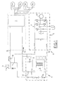
- FIG. 1 there is shown the diagram of the power circuit of an autonomous tram combining a number of the solutions listed above.
- This circuit comprises a traction system 1 supplying engines M1, M2, M3, M4 for driving the wheels of the vehicle.
- the traction system 1 is supplied on the one hand in conventional mode by a pantograph 2 from a catenary 3 and on the other hand, in autonomous mode by an autonomous power supply device on board the vehicle and designated by the general numerical reference 4.
- the on-board device 4 comprises a system 5 with kinetic energy accumulation and a system 6 of backup autonomy both connected to a common point 7 with the pantograph 2 for transmitting the power supply from the catenary 3 .
- the kinetic energy storage system 5 comprises a polyphase synchronous motor 10 with permanent magnets, the rotor of which is known per se, placed outside and acts as a mass of inertia.
- This motor is associated with a variable frequency electronic supply device 11 which makes it possible to regulate a fixed voltage as a function of the speed of the motor 10.
- the supply of a phase of the motor 10 by means of a bridge of transistors IGBT 12, is represented on the figure 1 .
- the rotor mass of the motor 10 is driven at a high speed.
- the motor In the discharge mode, the motor operates as a generator and supplies energy to the traction system 1.
- the supply voltage of the kinetic energy storage system on the high voltage network is set at a value between 700 V and 800 V, which allows operation of the traction system 1 identical, that it is powered by the catenary (typical voltage of 750V) or the kinetic energy storage system 5.
- the backup autonomy system 6 comprises a traction battery 14 to which is associated a charger 16 connected to the pantograph 2 in order to connect it to either the catenary 3 or to an external power supply circuit which will be described with reference to FIG. figure 2 .
- the backup autonomy system 6 can be connected by switches 17 in combination with a switch 18, to the traction system 1.
- a connection 20 allows the supply of the traction system 1 by the kinetic energy storage system 5.
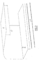
- FIG. 2 schematically shows a stop station for a tramway equipped with the feed system of the invention.
- This station comprises an awning 22 which carries a contact wire 23 located above the track 24 and powered by the high voltage sector, this wire being intended to cooperate with the pantograph 2 of the tramway to recharge the accumulation system kinetic energy 5 and backup autonomy system 6 during the tram stop in the station.
- the voltage levels delivered by the kinetic energy storage system 5, the catenary 3 and the contact wire 23, are compatible, which allows easy switching of these sources with respect to the user loads.
- Station energy harvesting is provided as follows.
- the principle of capture in station is identical to that under catenary.
- the pantograph 2 is reused and the capture is carried out by the wire 23 located at a minimum height (typically 3.60m to 4m) under the awning 22 of the station.
- This wire can be flexible or rigid and integrated into the architecture and urbanism of the stations as represented in the figure 2 .
- the descent of the pantograph is controlled by the order of departure of the driver, the starting of the vehicle is delayed and is effective only on feedback of the pantograph 2 in the low position.
- the rise and fall time of the pantograph at this collection height is of the order of 1 s.
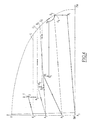
- the figure 3 shows schematically the management means implemented in the feed system according to the invention.
- These management means comprise sensors 25 for the speed of rotation of two traction motors M1 to M4, connected to a tachometer station 26.
- the traction system is associated with an electronic control circuit 28 which is connected on the one hand to a driving manipulator 30 and on the other hand, to an on-board computer network 32 from which it receives speed instructions.
- the on-board computer network 32 is connected to an on-board central computer 34 and tachometer 26.
- a current sensor 40 is connected in the line connecting the kinetic energy storage system 5 to the traction system 1.
- the energy management of the system according to the invention is ensured as follows.
- the measurement of energy is made from the measurement of the current I consumed or recovered by the kinetic energy storage system (according to its sign), because the system with kinetic energy accumulation regulates a constant voltage in a very wide range of rotation, which means that the current I is proportional to the power P.
- This measurement is performed by the electronic control circuit 36 of the kinetic energy accumulation system associated with the current sensor 40 and which integrates the energy consumed and the remaining energy by integration on a sampling step, taking also into account account in this calculation the corresponding yield values.
- the tramway conventionally has a speed measuring equipment (tachometer unit 26) which receives the speed measurements of two of the traction motors M1 and M4 and derives a reference speed value from the vehicle, as well as a speedometer. distance value traveled from a given moment (odometer function); this allows the central computer 34 of the vehicle to know its actual position on the course (interstation and position in the interstation).
- radio beacons located at different points of the route; these arrangements are optional but generally exist in a conventional manner on modern lines for operating assistance.
- the energy consumption under the nominal driving and operating conditions of the tramway on each interstation is measured during the preliminary testing phase on the line for different maximum speeds and is stored in the central computer 34 of each vehicle.
- the onboard central computer 34 For each interstation and at any given point by a distance step pk of the order of the length of the vehicle (30 to 40 m), the onboard central computer 34 therefore knows the nominal energy consumptions to provide E (v, pk ) for different maximum speeds v, until the next station stop.
- This speed value Vr is then transmitted by the on-board computer 34 to the traction system 1 which applies this limitation set of speed when the line manipulator 30 is in the traction position; a speed reduction signal is also issued in the driver's cabin.
- the kinetic energy storage system When the reduction in speed is too great or the speed sensor 38 of the kinetic energy storage system detects a threshold minimum speed of the flywheel of the engine 10, the kinetic energy storage system then regulates a voltage lower output, in order to adapt this voltage to the backup autonomy system voltage 6 so far backed up; an automatic switching is then performed on this backup system 6 by the electronic control circuit 36 which closes the switches 17 ( Fig.1 ).
- the battery system 14 allows the vehicle to travel in degraded mode at a reduced speed (typically 25 km / h) until the next station stop; this mode is an exceptional mode and the battery 14 is not solicited in number of cycles, so in life.
- the battery system is recharged by a specific charger in depot or from catenary 3 when the vehicle is traveling over catenary line zones ( Fig.1 ).
- the first start as well as the first course until the stop of the vehicle is represented by a loop designated by simple arrows.
- the total power consumed is less than the maximum power available on the kinetic energy storage system 5.
- the speed reaches a maximum value at the point E 1 and then remains at this value during the section E 1 F 1 .
- the section F 1 A 2 occurs braking with energy recovery.
- the second start and the second course until the next stop of the vehicle is represented by a loop A 2 B 2 C 2 D 2 E 2 A 3 designated by the double arrows.
- the power consumption is regulated by the traction system at the limit of the maximum characteristic of the kinetic accumulation system energy 5; during the traction phase, the central computer 24 measures overconsumption on the kinetic energy storage system 5 with respect to the consumption profile stored on this remote; a reduction in speed is therefore imposed on the vehicle.
- the speed increases but can not be maintained at the maximum speed so that during the section B 2 C 2 , the energy consumed is compared with a reduction energy mask. the speed setpoint.
- the third start is assumed unexpected, which induces overconsumption with maximum speed reduction.
- the third start and the third run to the stop are represented by the loop A 3 B 3 C 3 D 3 E 3 F 3 designated by triple arrows.
- the vehicle switches from standstill to a maximum speed compatible with the energy remaining available in the kinetic energy storage system 5.
- braking during the section E 3 F 3 provides energy recovery which when stopping the vehicle at point F 3 brings the available energy to the discharge limit of the steering wheel, so that if the stopping at point F 3 is at a station with charging means, the wheel 10 of the engine can be restarted so as to achieve sufficient energy during the parking time of the vehicle to allow it to continue its course normally.
- the power system for electric traction vehicle allows the vehicle to present performance very well suited to urban routes.
Applications Claiming Priority (2)
| Application Number | Priority Date | Filing Date | Title |
|---|---|---|---|
| FR9810830A FR2782680B1 (fr) | 1998-08-28 | 1998-08-28 | Systeme d'alimentation d'un vehicule a traction electrique |
| FR9810830 | 1998-08-28 |
Publications (2)
| Publication Number | Publication Date |
|---|---|
| EP0982176A1 EP0982176A1 (fr) | 2000-03-01 |
| EP0982176B1 true EP0982176B1 (fr) | 2011-10-12 |
Family
ID=9529964
Family Applications (1)
| Application Number | Title | Priority Date | Filing Date |
|---|---|---|---|
| EP99402060A Expired - Lifetime EP0982176B1 (fr) | 1998-08-28 | 1999-08-13 | Système d'alimentation d'un véhicule à traction électrique |
Country Status (7)
| Country | Link |
|---|---|
| US (1) | US6294886B1 (ja) |
| EP (1) | EP0982176B1 (ja) |
| JP (1) | JP3234203B2 (ja) |
| AT (1) | ATE528166T1 (ja) |
| CA (1) | CA2280417C (ja) |
| ES (1) | ES2371852T3 (ja) |
| FR (1) | FR2782680B1 (ja) |
Families Citing this family (32)
| Publication number | Priority date | Publication date | Assignee | Title |
|---|---|---|---|---|
| FR2819759B1 (fr) | 2001-01-24 | 2003-05-23 | Alstom | Systeme d'alimentation d'un vehicule a traction electrique |
| FR2822764B1 (fr) * | 2001-03-29 | 2003-05-16 | Alstom | Procede et dispositif de pilotage de l'alimentation en energie d'un vehicule a traction electrique destine a fonctionner en mode d'alimentation externe ou en mode d'alimentation autonome |
| US6753619B2 (en) * | 2002-08-06 | 2004-06-22 | Visteon Global Technologies, Inc. | Fly-wheel-based regenerative energy management system |
| DE10341512A1 (de) * | 2003-09-05 | 2005-04-14 | Bombardier Transportation Gmbh | Stromrichteranordnung |
| FR2871744B1 (fr) * | 2004-06-21 | 2008-02-22 | Alstom Sa | Dispositif d'alimentation embarque sur un vehicule de traction, procede d'alimentation et support d'enregistrement de ce procede |
| FR2873332B1 (fr) | 2004-07-21 | 2006-11-03 | Alstom Transport Sa | Systeme et sous-station d'alimentation electrique d'un reseau de traction |
| ES2258386B1 (es) * | 2004-08-11 | 2007-12-01 | Ferrocarriles De Via Estrecha Feve | Locomotora de ferrocarril de traccion dual electrica y diesel-electrica. |
| EP1864849A1 (fr) * | 2006-05-19 | 2007-12-12 | Siemens Transportation System S.A.S. | Système de régulation d'énergie pour un véhicule |
| JP4841441B2 (ja) * | 2007-01-09 | 2011-12-21 | 川崎重工業株式会社 | 鉄道車両のバッテリ用充電装置 |
| JP4568736B2 (ja) * | 2007-02-27 | 2010-10-27 | 三菱重工業株式会社 | 架線レス交通システム及びその充電方法 |
| FR2918004B1 (fr) * | 2007-06-29 | 2009-09-11 | Alstom Transport Sa | Installation d'alimentation d'un vehicule ferroviaire |
| DE102009008549A1 (de) * | 2009-02-12 | 2010-08-19 | Bombardier Transportation Gmbh | Anordnung zum Betreiben von Verbrauchern in einem Schienenfahrzeug mit elektrischer Energie, wahlweise aus einem Energieversorgungsnetz oder aus einer Motor-Generator-Kombination |
| CN101503065B (zh) * | 2009-02-23 | 2011-05-04 | 吴加林 | 一种铁路机车用的无分相式牵引供电装置 |
| DE102009039684A1 (de) | 2009-09-02 | 2011-03-31 | Voith Patent Gmbh | Hybridantrieb für Schienenfahrzeuge |
| DE102009047065A1 (de) * | 2009-11-24 | 2011-05-26 | SB LiMotive Company Ltd., Suwon | Serienschaltung von Schaltreglern zur Energieübertragung in Batteriesystemen |
| CN102195284B (zh) * | 2010-03-16 | 2014-12-17 | 施耐德东芝换流器欧洲公司 | 应用超级电容器的驱动系统的直流网络管理 |
| CN104221277B (zh) * | 2011-11-22 | 2018-09-18 | 昆腾燃料系统有限责任公司 | 组合充电器及动力装置 |
| US20130140100A1 (en) * | 2011-12-01 | 2013-06-06 | Caterpillar Inc. | Control Strategy For Powering Auxiliary Device In Trolley Capable Mining Truck |
| US9296300B2 (en) | 2012-04-13 | 2016-03-29 | General Electric Company | Method and system for powering a vehicle |
| ES2604177T3 (es) * | 2012-07-03 | 2017-03-03 | Visedo Oy | Un almacenamiento de energía capacitivo para una máquina de trabajo móvil |
| DE102012216312A1 (de) * | 2012-09-13 | 2014-03-13 | Siemens Aktiengesellschaft | Schienenfahrzeug mit Batteriebetrieb |
| PT3007925T (pt) | 2013-06-14 | 2019-07-10 | Hedgehog Applications B V | Método e sistema de utilização da energia de travagem regenerativa de veículos ferroviários |
| CN103434411B (zh) * | 2013-08-29 | 2016-03-02 | 武汉英康汇通电气有限公司 | 一种在线充电式电动车制动能量的回收系统 |
| DE102013226356A1 (de) * | 2013-10-02 | 2015-04-02 | Scania Cv Ab | Fahrzeug |
| US9685276B2 (en) | 2014-01-03 | 2017-06-20 | Visedo Oy | Capacitive energy-storage for a mobile working machine |
| CN104002690B (zh) * | 2014-06-06 | 2016-02-24 | 重庆大学 | 一种装有飞轮助力装置的增程式电动汽车动力系统 |
| JP6730842B2 (ja) * | 2015-05-05 | 2020-07-29 | ロールス−ロイス コーポレイション | 航空機の推進およびリフトのための電気直結駆動装置 |
| CN105774569B (zh) * | 2016-03-11 | 2017-11-10 | 中车青岛四方车辆研究所有限公司 | 集成储能装置充放电控制的轨道车辆牵引逆变系统及方法 |
| CN106240383A (zh) * | 2016-08-12 | 2016-12-21 | 西安科技大学 | 一种直流车辆牵引系统 |
| CN106427606A (zh) * | 2016-11-01 | 2017-02-22 | 广州电力机车有限公司 | 一种利用超级电容的自卸车动力系统 |
| CN113895238B (zh) * | 2021-09-15 | 2024-01-26 | 哈尔滨理工大学 | 一种基于mrpp制动转矩限制器的再生制动控制方法 |
| CN116872789B (zh) * | 2023-09-08 | 2023-11-10 | 强钧能源技术(深圳)有限公司 | 一种模块化储能电池充放电管理系统 |
Family Cites Families (14)
| Publication number | Priority date | Publication date | Assignee | Title |
|---|---|---|---|---|
| DE2405198A1 (de) * | 1973-02-15 | 1974-08-22 | Oscar Dr Ing Bossi | Batteriebetriebenes transportsystem, insbesondere fuer den oeffentlichen nahverkehr |
| USRE29994E (en) * | 1973-02-15 | 1979-05-15 | Electric traction transportation system with storage battery powered vehicles and fast recharge at the vehicle stops | |
| US4075948A (en) * | 1974-01-31 | 1978-02-28 | Minovitch Michael Andrew | Rapid transit system |
| US4096423A (en) * | 1976-03-01 | 1978-06-20 | General Electric Company | Direct current motor chopper propulsion system |
| US4095154A (en) * | 1976-10-21 | 1978-06-13 | General Electric Company | Regenerative braking system for a chopper controlled electric traction motor |
| AT370043B (de) * | 1980-01-22 | 1983-02-25 | Siemens Ag Oesterreich | Stromversorgungseinrichtung fuer elektrofahrzeuge |
| US5492192A (en) * | 1994-08-22 | 1996-02-20 | General Motors Corporation | Electric vehicle with traction control |
| DE9415770U1 (de) * | 1994-09-30 | 1994-12-15 | Abb Henschell Ag | Schienengebundenes Dieseltriebfahrzeug |
| US5670861A (en) * | 1995-01-17 | 1997-09-23 | Norvik Tractions Inc. | Battery energy monitoring circuits |
| US5731645A (en) * | 1996-02-05 | 1998-03-24 | Magnetic Bearing Technologies, Inc. | Integrated motor/generator/flywheel utilizing a solid steel rotor |
| US5767591A (en) * | 1996-09-09 | 1998-06-16 | Active Power, Inc. | Method and apparatus for providing startup power to a genset-backed uninterruptible power supply |
| FR2756118B1 (fr) * | 1996-11-20 | 1999-02-05 | Moteurs Fox | Machine electrique motrice a stockage inertiel alimentee par une source de tension continue autonome |
| US6020657A (en) * | 1997-08-27 | 2000-02-01 | Perfect Power Inc. | Power supply for providing instantaneous energy during utility power outages |
| US5929595A (en) * | 1997-11-21 | 1999-07-27 | Lockheed Martin Corporation | Hybrid electric vehicle with traction motor drive allocated between battery and auxiliary source depending upon battery charge state |
-
1998
- 1998-08-28 FR FR9810830A patent/FR2782680B1/fr not_active Expired - Lifetime
-
1999
- 1999-08-13 EP EP99402060A patent/EP0982176B1/fr not_active Expired - Lifetime
- 1999-08-13 CA CA002280417A patent/CA2280417C/fr not_active Expired - Lifetime
- 1999-08-13 ES ES99402060T patent/ES2371852T3/es not_active Expired - Lifetime
- 1999-08-13 AT AT99402060T patent/ATE528166T1/de active
- 1999-08-27 JP JP24190799A patent/JP3234203B2/ja not_active Expired - Fee Related
- 1999-08-30 US US09/384,979 patent/US6294886B1/en not_active Expired - Lifetime
Also Published As
| Publication number | Publication date |
|---|---|
| US6294886B1 (en) | 2001-09-25 |
| JP3234203B2 (ja) | 2001-12-04 |
| CA2280417A1 (fr) | 2000-02-28 |
| CA2280417C (fr) | 2004-04-20 |
| ES2371852T3 (es) | 2012-01-10 |
| FR2782680A1 (fr) | 2000-03-03 |
| EP0982176A1 (fr) | 2000-03-01 |
| FR2782680B1 (fr) | 2000-11-17 |
| JP2000078702A (ja) | 2000-03-14 |
| ATE528166T1 (de) | 2011-10-15 |
Similar Documents
| Publication | Publication Date | Title |
|---|---|---|
| EP0982176B1 (fr) | Système d'alimentation d'un véhicule à traction électrique | |
| EP1245432B1 (fr) | Procédé et dispositif de pilotage de l'alimentation en énergie électrique d'un véhicule a traction électrique destiné à fonctionner en mode d'alimentation externe ou en mode d'alimentation autonome | |
| CA2368037C (fr) | Systeme d'alimentation d'un vehicule a traction electrique | |
| EP2162313B1 (fr) | Installation d'alimentation d'un vehicule ferroviaire | |
| EP1725424B1 (fr) | Systeme d'alimentation en energie electrique a tres basse tension pour vehicule a traction electrique a stockage d'energie embarque | |
| CA2426372C (fr) | Procede et dispositif pour le controle et la regulation de la puissance consommee par un systeme de transport | |
| CA2778162C (fr) | Procede d'alimentation electrique d'un vehicule ferroviaire, systeme d'alimentation en station, systeme de stockage d'energie embarque et vehicule ferroviaire associes | |
| CA2988845C (fr) | Ensemble constitue d'un vehicule electrique et d'un systeme de recharge stationnaire par conduction; systeme, installation, vehicule et procede associes | |
| EP0968873B1 (fr) | Réseau de transport en commun avec véhicules électriques | |
| EP2231438A2 (fr) | Systeme d'alimentation pour véhicule a traction électrique a stockage d'énergie embarque | |
| JP2020074660A (ja) | 機関車推進システム | |
| JP3768982B2 (ja) | 間歇給電式電気車両システムおよび電気車両 | |
| EP3323661B1 (fr) | Système de transport à alimentation électrique par le sol | |
| JP6324682B2 (ja) | 保守用車両 | |
| EP1167112B1 (fr) | Système d'alimentation en énergie de véhicules à traction électrique | |
| TWI788751B (zh) | 再生煞車系統 | |
| EP3915822A1 (fr) | Procédé d'alimentation d'un ensemble de moteurs de traction embarqué dans un véhicule, dispositif électronique de contrôle d'alimentation et ensemble de moteurs de traction associé | |
| FR2897018A1 (fr) | Rame de metro. |
Legal Events
| Date | Code | Title | Description |
|---|---|---|---|
| PUAI | Public reference made under article 153(3) epc to a published international application that has entered the european phase |
Free format text: ORIGINAL CODE: 0009012 |
|
| AK | Designated contracting states |
Kind code of ref document: A1 Designated state(s): AT BE CH CY DE DK ES FI FR GB GR IE IT LI LU MC NL PT SE |
|
| AX | Request for extension of the european patent |
Free format text: AL;LT;LV;MK;RO;SI |
|
| 17P | Request for examination filed |
Effective date: 20000408 |
|
| AKX | Designation fees paid |
Free format text: AT BE CH CY DE DK ES FI FR GB GR IE IT LI LU MC NL PT SE |
|
| RAP1 | Party data changed (applicant data changed or rights of an application transferred) |
Owner name: ALSTOM HOLDINGS |
|
| RAP1 | Party data changed (applicant data changed or rights of an application transferred) |
Owner name: ALSTOM HOLDINGS |
|
| 17Q | First examination report despatched |
Effective date: 20071219 |
|
| RAP1 | Party data changed (applicant data changed or rights of an application transferred) |
Owner name: ALSTOM TRANSPORT SA |
|
| GRAP | Despatch of communication of intention to grant a patent |
Free format text: ORIGINAL CODE: EPIDOSNIGR1 |
|
| GRAS | Grant fee paid |
Free format text: ORIGINAL CODE: EPIDOSNIGR3 |
|
| GRAA | (expected) grant |
Free format text: ORIGINAL CODE: 0009210 |
|
| AK | Designated contracting states |
Kind code of ref document: B1 Designated state(s): AT BE CH CY DE DK ES FI FR GB GR IE IT LI LU MC NL PT SE |
|
| REG | Reference to a national code |
Ref country code: GB Ref legal event code: FG4D Free format text: NOT ENGLISH |
|
| REG | Reference to a national code |
Ref country code: CH Ref legal event code: EP |
|
| REG | Reference to a national code |
Ref country code: IE Ref legal event code: FG4D |
|
| REG | Reference to a national code |
Ref country code: DE Ref legal event code: R096 Ref document number: 69943776 Country of ref document: DE Effective date: 20111208 |
|
| REG | Reference to a national code |
Ref country code: ES Ref legal event code: FG2A Ref document number: 2371852 Country of ref document: ES Kind code of ref document: T3 Effective date: 20120110 |
|
| REG | Reference to a national code |
Ref country code: NL Ref legal event code: VDEP Effective date: 20111012 |
|
| REG | Reference to a national code |
Ref country code: IE Ref legal event code: FD4D |
|
| PG25 | Lapsed in a contracting state [announced via postgrant information from national office to epo] |
Ref country code: GR Free format text: LAPSE BECAUSE OF FAILURE TO SUBMIT A TRANSLATION OF THE DESCRIPTION OR TO PAY THE FEE WITHIN THE PRESCRIBED TIME-LIMIT Effective date: 20120113 Ref country code: SE Free format text: LAPSE BECAUSE OF FAILURE TO SUBMIT A TRANSLATION OF THE DESCRIPTION OR TO PAY THE FEE WITHIN THE PRESCRIBED TIME-LIMIT Effective date: 20111012 Ref country code: NL Free format text: LAPSE BECAUSE OF FAILURE TO SUBMIT A TRANSLATION OF THE DESCRIPTION OR TO PAY THE FEE WITHIN THE PRESCRIBED TIME-LIMIT Effective date: 20111012 Ref country code: PT Free format text: LAPSE BECAUSE OF FAILURE TO SUBMIT A TRANSLATION OF THE DESCRIPTION OR TO PAY THE FEE WITHIN THE PRESCRIBED TIME-LIMIT Effective date: 20120213 |
|
| PG25 | Lapsed in a contracting state [announced via postgrant information from national office to epo] |
Ref country code: CY Free format text: LAPSE BECAUSE OF FAILURE TO SUBMIT A TRANSLATION OF THE DESCRIPTION OR TO PAY THE FEE WITHIN THE PRESCRIBED TIME-LIMIT Effective date: 20111012 |
|
| PG25 | Lapsed in a contracting state [announced via postgrant information from national office to epo] |
Ref country code: IE Free format text: LAPSE BECAUSE OF FAILURE TO SUBMIT A TRANSLATION OF THE DESCRIPTION OR TO PAY THE FEE WITHIN THE PRESCRIBED TIME-LIMIT Effective date: 20111012 Ref country code: DK Free format text: LAPSE BECAUSE OF FAILURE TO SUBMIT A TRANSLATION OF THE DESCRIPTION OR TO PAY THE FEE WITHIN THE PRESCRIBED TIME-LIMIT Effective date: 20111012 |
|
| PLBE | No opposition filed within time limit |
Free format text: ORIGINAL CODE: 0009261 |
|
| STAA | Information on the status of an ep patent application or granted ep patent |
Free format text: STATUS: NO OPPOSITION FILED WITHIN TIME LIMIT |
|
| 26N | No opposition filed |
Effective date: 20120713 |
|
| REG | Reference to a national code |
Ref country code: DE Ref legal event code: R097 Ref document number: 69943776 Country of ref document: DE Effective date: 20120713 |
|
| PG25 | Lapsed in a contracting state [announced via postgrant information from national office to epo] |
Ref country code: MC Free format text: LAPSE BECAUSE OF NON-PAYMENT OF DUE FEES Effective date: 20120831 |
|
| GBPC | Gb: european patent ceased through non-payment of renewal fee |
Effective date: 20120813 |
|
| PG25 | Lapsed in a contracting state [announced via postgrant information from national office to epo] |
Ref country code: GB Free format text: LAPSE BECAUSE OF NON-PAYMENT OF DUE FEES Effective date: 20120813 |
|
| REG | Reference to a national code |
Ref country code: CH Ref legal event code: PUE Owner name: ALSTOM TRANSPORT TECHNOLOGIES, FR Free format text: FORMER OWNER: ALSTOM TRANSPORT SA, FR |
|
| REG | Reference to a national code |
Ref country code: ES Ref legal event code: PC2A Owner name: ALSTOM TRANSPORT TECHNOLOGIES Effective date: 20140211 |
|
| REG | Reference to a national code |
Ref country code: DE Ref legal event code: R081 Ref document number: 69943776 Country of ref document: DE Owner name: ALSTOM TRANSPORT TECHNOLOGIES, FR Free format text: FORMER OWNER: ALSTOM FRANCE S.A., PARIS, FR Effective date: 20111019 Ref country code: DE Ref legal event code: R081 Ref document number: 69943776 Country of ref document: DE Owner name: ALSTOM TRANSPORT TECHNOLOGIES, FR Free format text: FORMER OWNER: ALSTOM TRANSPORT SA, LEVALLOIS-PERRET, FR Effective date: 20140213 |
|
| PG25 | Lapsed in a contracting state [announced via postgrant information from national office to epo] |
Ref country code: LU Free format text: LAPSE BECAUSE OF NON-PAYMENT OF DUE FEES Effective date: 20120813 |
|
| REG | Reference to a national code |
Ref country code: CH Ref legal event code: NV Representative=s name: BUGNION S.A., CH |
|
| REG | Reference to a national code |
Ref country code: FR Ref legal event code: TP Owner name: ALSTOM TRANSPORT TECHNOLOGIES, FR Effective date: 20140926 |
|
| REG | Reference to a national code |
Ref country code: AT Ref legal event code: PC Ref document number: 528166 Country of ref document: AT Kind code of ref document: T Owner name: ALSTOM TRANSPORT TECHNOLOGIES, FR Effective date: 20140919 |
|
| REG | Reference to a national code |
Ref country code: FR Ref legal event code: PLFP Year of fee payment: 18 |
|
| REG | Reference to a national code |
Ref country code: FR Ref legal event code: PLFP Year of fee payment: 19 |
|
| REG | Reference to a national code |
Ref country code: DE Ref legal event code: R081 Ref document number: 69943776 Country of ref document: DE Owner name: ALSTOM TRANSPORT TECHNOLOGIES, FR Free format text: FORMER OWNER: ALSTOM TRANSPORT TECHNOLOGIES, LEVALLOIS-PERRET, FR |
|
| REG | Reference to a national code |
Ref country code: CH Ref legal event code: PCOW Free format text: NEW ADDRESS: 48 RUE ALBERT DHALENNE, 93400 SAINT-OUEN (FR) |
|
| REG | Reference to a national code |
Ref country code: FR Ref legal event code: CA Effective date: 20180103 |
|
| REG | Reference to a national code |
Ref country code: BE Ref legal event code: PD Owner name: ALSTOM TRANSPORT TECHNOLOGIES; FR Free format text: DETAILS ASSIGNMENT: CHANGE OF OWNER(S), AUTRE, ADRESSE Effective date: 20171031 |
|
| REG | Reference to a national code |
Ref country code: FR Ref legal event code: PLFP Year of fee payment: 20 |
|
| PGFP | Annual fee paid to national office [announced via postgrant information from national office to epo] |
Ref country code: DE Payment date: 20180823 Year of fee payment: 20 Ref country code: ES Payment date: 20180921 Year of fee payment: 20 Ref country code: IT Payment date: 20180830 Year of fee payment: 20 Ref country code: FR Payment date: 20180827 Year of fee payment: 20 |
|
| PGFP | Annual fee paid to national office [announced via postgrant information from national office to epo] |
Ref country code: FI Payment date: 20180822 Year of fee payment: 20 Ref country code: AT Payment date: 20180822 Year of fee payment: 20 Ref country code: BE Payment date: 20180821 Year of fee payment: 20 Ref country code: CH Payment date: 20180822 Year of fee payment: 20 |
|
| REG | Reference to a national code |
Ref country code: DE Ref legal event code: R079 Ref document number: 69943776 Country of ref document: DE Free format text: PREVIOUS MAIN CLASS: B60L0011180000 Ipc: B60L0050500000 |
|
| REG | Reference to a national code |
Ref country code: DE Ref legal event code: R071 Ref document number: 69943776 Country of ref document: DE |
|
| REG | Reference to a national code |
Ref country code: CH Ref legal event code: PL |
|
| REG | Reference to a national code |
Ref country code: BE Ref legal event code: MK Effective date: 20190813 |
|
| REG | Reference to a national code |
Ref country code: AT Ref legal event code: MK07 Ref document number: 528166 Country of ref document: AT Kind code of ref document: T Effective date: 20190813 |
|
| REG | Reference to a national code |
Ref country code: ES Ref legal event code: FD2A Effective date: 20200721 |
|
| PG25 | Lapsed in a contracting state [announced via postgrant information from national office to epo] |
Ref country code: ES Free format text: LAPSE BECAUSE OF EXPIRATION OF PROTECTION Effective date: 20190814 |