EP0982054A1 - Flipper mit einer Anzeigevorrichtung - Google Patents
Flipper mit einer Anzeigevorrichtung Download PDFInfo
- Publication number
- EP0982054A1 EP0982054A1 EP99402080A EP99402080A EP0982054A1 EP 0982054 A1 EP0982054 A1 EP 0982054A1 EP 99402080 A EP99402080 A EP 99402080A EP 99402080 A EP99402080 A EP 99402080A EP 0982054 A1 EP0982054 A1 EP 0982054A1
- Authority
- EP
- European Patent Office
- Prior art keywords
- playfield
- display
- cabinet
- pinball game
- display assembly
- Prior art date
- Legal status (The legal status is an assumption and is not a legal conclusion. Google has not performed a legal analysis and makes no representation as to the accuracy of the status listed.)
- Withdrawn
Links
Images


Classifications
-
- F—MECHANICAL ENGINEERING; LIGHTING; HEATING; WEAPONS; BLASTING
- F23—COMBUSTION APPARATUS; COMBUSTION PROCESSES
- F23G—CREMATION FURNACES; CONSUMING WASTE PRODUCTS BY COMBUSTION
- F23G7/00—Incinerators or other apparatus for consuming industrial waste, e.g. chemicals
- F23G7/06—Incinerators or other apparatus for consuming industrial waste, e.g. chemicals of waste gases or noxious gases, e.g. exhaust gases
- F23G7/08—Incinerators or other apparatus for consuming industrial waste, e.g. chemicals of waste gases or noxious gases, e.g. exhaust gases using flares, e.g. in stacks
- F23G7/085—Incinerators or other apparatus for consuming industrial waste, e.g. chemicals of waste gases or noxious gases, e.g. exhaust gases using flares, e.g. in stacks in stacks
Definitions
- the present invention relates generally to pinball games and, more particularly, relates to a pinball game display located in close proximity to, but not fastened to, a rear portion of a pinball playfield so that the display can be easily viewed by a player during game play and, yet, allows the play-field to be easily serviced for maintenance and troubleshooting purposes without interference from the display.
- Pinball games generally include an inclined playfield housed within a game cabinet and supporting a rolling ball (i.e.. pinball).
- a generally vertical backbox extends upward from a rear portion of the game cabinet and houses both a video display and game control circuitry.
- a plurality of play features are arranged on the playfield.
- a game player uses a pair of mechanical flippers mounted at one end of the playfield to propel the rolling ball at the various play features on the playfield to score points and control the play of the game.
- the video display generally shows player scores and provides special effects and suggestions to a player in response to certain events occurring on the playfield during game play.
- the special effects and suggestions on the display are intended to enhance the appeal of the pinball game.
- the game control circuitry may cause the display to show an explosion in response to the rolling ball actuating a particular switch on the playfield. Switches are generally associated with the play features such that a play feature switch is actuated in response to the rolling ball impacting the associated play feature.
- the game control circuitry generally causes a sound generator to generate sounds consistent with the special effects and suggestions shown on the display.
- a drawback of mounting the video display in the backbox is that the display is largely segregated from the playfield. Consequently, during game play, a player must divert his or her eyes away from events occurring on the playfield in order to view the scores, special effects, and suggestions provided by the display. Since keeping the rolling ball on the playfield and scoring points is generally of paramount concern to the player, the player may give minimal regard to the scores, special effects, and suggestions on the display. If the player misses some of the scores, special effects, and suggestions on the display due to its segregation from the playfield, the purpose of the display is defeated to some extent.
- an object of the present invention is to provide a display for a pinball game that can be easily viewed by a player during game play and, yet, allows the playfield to be easily serviced for maintenance and troubleshooting purposes without interference from the display.
- a pinball game including a cabinet, an inclined playfield, and a video display.
- the inclined playfield supports a rolling ball and a plurality of play features thereon.
- the cabinet includes a pair of opposing side walls and a rear wall extending between the opposing side walls.
- the playfield is housed within the cabinet such that the playfield is partially encompassed by the side walls and rear wall of the cabinet.
- An upper portion of the rear cabinet wall extends above a level of a rear portion of the playfield.
- the video display is mounted to this upper portion of the rear cabinet wall and is located in close proximity to the rear portion of the playfield.
- the angle between a front surface of the display and an upper surface of the playfield is preferably greater than 90 degrees but less than 135 degrees.
- the angle of the display relative to the playfield is greater than 90 degrees, distracting reflections of the play features on the front surface of the display are minimized.
- the front surface of the display is nearly perpendicular to a sight line extending between the eyes of a typical game player and the display.
- a generally vertical backbox preferably extends upward from a rear portion of the cabinet. Since, unlike most existing pinball games, the backbox is not used to house the video display, the backbox may use the space vacated by the display for additional game graphics, another display, or additional electrical or mechanical pinball game components.
- FIG. 1 depicts a pinball game 10 including a video display assembly 12 embodying the present invention.
- the pinball game 10 includes an inclined playfield 14 housed within a game cabinet 16 and supporting a rolling ferromagnetic ball 18 and a plurality of play features 19 thereon.
- the rolling ball 18 can be propelled across the playfield 14 by a pair of player-operated flippers 20.
- a generally vertical backbox 22 extends upward from a rear portion of the cabinet 16 and houses a game controller and other electronics for controlling play of the game. Since, unlike most existing pinball games, the backbox 22 is not used to house the video display assembly 12, the backbox 22 may use the space vacated by the display for additional game graphics, another display, or additional electrical or mechanical pinball game components.
- a player manipulates a plunger 24 to shoot the rolling ball 18 up an alley 26 onto the playfield 14.
- the player presses flipper switches 28 (see FIG. 5) to activate the flippers 20 and thereby propel the rolling ball 18 toward the play features on the playfield 14.
- the playfield 14 incorporates a number of playfield features. FIG. 1 shows only a few of these play features 19 for clarity.
- the game cabinet 16 includes a pair of opposing side walls 30 and 32, a rear wall 34, and a front wall 36 opposing the rear wall 34.
- the rear and front walls 34 and 36 extend between the opposing side walls 30 and 32.
- the playfield 14 is housed within the cabinet 16 such that the playfield 14 is positioned below upper edges of the cabinet walls 30, 32, 34, and 36 and is encompassed by the cabinet walls. Consequently, upper portions of the cabinet walls extend above levels of respective adjacent portions of the playfield 14.
- an upper portion 34a (FIG. 5) of the rear cabinet wall 34 extends above a level of an adjacent rear portion of the playfield 14.
- the cabinet 16 is elevated above a ground surface 38 by four corner legs 40 (only two legs shown) mounted to the respective four corners of the cabinet 16 and extending downward from the cabinet 16 to the ground surface 38.
- the video display assembly 12 has been strategically lowered from its conventional location in the vertical backbox 22 to a location just above the playfield 14 to provide for improved integration with game play.
- the display assembly 12 is mounted to the upper portion 34a of the rear cabinet wall 34 and is located immediately above the rear portion of the playfield 14 such that the display assembly 12 appears to "float" over the playfield 14.
- the display assembly 12 can be easily viewed by a player 42 during game play and, yet, allows the playfield 14 to be easily serviced for maintenance and troubleshooting purposes without interference from the display assembly 12.
- the player 42 can view scores, special effects, and suggestions shown on the display assembly 12 without sacrificing the attention he or she must give to events occurring the playfield 14 in order to keep the rolling ball 18 in play.
- the playfield 14 may easily be removed from the cabinet 16 without interference from the display assembly 12.
- the playfield 14 is preferably mounted to the cabinet 16 using a mounting systems that allows the playfield 14 to be quickly slid and pivoted relative to the cabinet 16.
- a mounting system may, for example, include grooves 46 formed in the cabinet side walls 30 and 32 and spring-biased pivot pins 48 mounted on the playfield 14 for travel within the respective grooves 46.
- Guide bumpers 50 only one of which is shown in FIG. 6, are fastened.to the underside of the playfield 14.
- the bumpers 50 prevent damage to game components that are attached to the underside of the playfield 14 by preventing contact between the components and the cabinet walls during movement of the playfield. Further details concerning the playfield mounting system may be obtained from U.S. Patent No. 5.536.082 to Ritchie et al., which is incorporated herein by reference in its entirety.
- the angle ⁇ between a front surface of the display assembly 12 and an upper surface of the playfield 14 is preferably greater than 90 degrees but less than 135 degrees.
- the angle of the display assembly 12 relative to the playfield 14 is greater than 90 degrees, distracting reflections of the play features 19 (see FIG. 1) on the front surface of the display assembly 12 are minimized.
- the front surface of the display assembly 12 is nearly perpendicular to a sight line 44 extending between the eyes of a typical game player 42 and the display assembly 12.
- the angle between the display assembly 12 and the playfield 14 is between about 100 degrees and about 125 degrees and is most preferably between about 110 degrees and about 120 degrees.
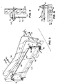
- FIGS. 2, 3, and 4 illustrate the video display assembly 12 in greater detail.
- the display assembly 12 includes a mounting frame 52, a video display 54, and a protective plastic cover 56.
- the display 54 is attached to the mounting frame 52 by a plurality of fasteners 58 in the form of screws, bolts, rivets, or the like.
- the fasteners 58 are inserted through respective aligned holes formed in the mounting frame 52 and the display 54.
- spacers 60 (FIGS. 3 and 4) are telescopically mounted over the respective fasteners 58 and disposed between the mounting frame 52 and the display 54.
- a protective paper or plastic backing 55 is preferably applied to a rear surface of the display.
- the display 54 and the backing 55 are secured adjacent to each other by virtue of the spacers 60 pressing against the display 54 on one side of the display/backing combination and fastener washers 61 pressing against the backing 55 on the other side.
- the protective plastic cover 56 is affixed to the mounting frame 52 by a plurality of fasteners 63 in the form of screws, bolts, rivets, or the like. The fasteners 63 are inserted through respective aligned holes formed in the cover 56 and the mounting frame 52.
- the mounting frame 52 is preferably composed of wood or rigid plastic and includes a generally rectangular opening 62 through which a substantial portion of the display 54 may be seen by a player.
- the mounting frame 52 preferably includes artwork applied to its front surface and is shaped along its periphery.
- the peripheral shape and dimensions of the plastic cover 56 preferably correspond to the peripheral shape and dimensions of the mounting frame 52.
- the display 54 is preferably a digital dot-matrix display.
- One such dot-matrix display is commercially available as model no. PD01-B220 (Plasmadot "Dot Matrix Gas Plasma” display) from Cherry Electrical Products Company of Waukegan, Illinois.
- the display 54 includes on-board circuitry 64 electrically connected to a main power supply and to a game controller in the backbox 22 (see FIGS. 1 and 5).
- the game controller sends video signals to the circuitry 64 to control the digital graphics shown on display 54.
- the graphics may, for example, include player scores, special effects, and text.
Applications Claiming Priority (2)
| Application Number | Priority Date | Filing Date | Title |
|---|---|---|---|
| US136900 | 1998-08-19 | ||
| US09/136,900 US5975885A (en) | 1998-08-19 | 1998-08-19 | Flare stack |
Publications (1)
| Publication Number | Publication Date |
|---|---|
| EP0982054A1 true EP0982054A1 (de) | 2000-03-01 |
Family
ID=22474915
Family Applications (1)
| Application Number | Title | Priority Date | Filing Date |
|---|---|---|---|
| EP99402080A Withdrawn EP0982054A1 (de) | 1998-08-19 | 1999-08-18 | Flipper mit einer Anzeigevorrichtung |
Country Status (2)
| Country | Link |
|---|---|
| US (1) | US5975885A (de) |
| EP (1) | EP0982054A1 (de) |
Families Citing this family (9)
| Publication number | Priority date | Publication date | Assignee | Title |
|---|---|---|---|---|
| CA2413553C (en) * | 2002-12-04 | 2008-07-29 | Robert C. Rajewski | Flare stack operating on coanda principle |
| US20060105276A1 (en) * | 2004-11-16 | 2006-05-18 | James Wilkins | Linear Coanda flare methods and apparatus |
| US20070281266A1 (en) * | 2006-05-18 | 2007-12-06 | Rajewski Robert C | Flare stack |
| US20070281251A1 (en) * | 2006-05-19 | 2007-12-06 | Diamond Qc Technologies Inc. | Alternate atomizing medium for burning efficiency of emulsion fuels, heavy oils and bitumens |
| EP2221549A1 (de) * | 2009-02-24 | 2010-08-25 | Siemens Aktiengesellschaft | Einrichtung zum Abblasen eines explosiblen Gases |
| US9816705B2 (en) | 2014-11-18 | 2017-11-14 | Honeywell International Inc. | Flare burner for a combustible gas |
| GB201610845D0 (en) * | 2016-06-21 | 2016-08-03 | Syngas Products Ltd | Flare with spuds |
| US10598375B2 (en) | 2016-11-01 | 2020-03-24 | Honeywell International Inc. | Asymmetrical and offset flare tip for flare burners |
| US11655978B2 (en) * | 2019-02-20 | 2023-05-23 | Moneyhun Equipment Sales & Services Co. | Flare tip assembly |
Citations (2)
| Publication number | Priority date | Publication date | Assignee | Title |
|---|---|---|---|---|
| GB2124505A (en) * | 1982-07-06 | 1984-02-22 | Bally Mfg Corp | Combination video and surface projectile apparatus |
| EP0502275A1 (de) * | 1991-03-04 | 1992-09-09 | Williams Electronics Games, Inc. | Angetriebenes Kugelspiel mit integrierter Animationsanzeige |
Family Cites Families (4)
| Publication number | Priority date | Publication date | Assignee | Title |
|---|---|---|---|---|
| GB1593391A (en) * | 1977-01-28 | 1981-07-15 | British Petroleum Co | Flare |
| US4464110A (en) * | 1980-12-10 | 1984-08-07 | The British Petroleum Company Limited | Flare using a Coanda director surface |
| DE3569020D1 (en) * | 1984-03-02 | 1989-04-27 | British Petroleum Co Plc | Flare |
| GB2156502A (en) * | 1984-03-30 | 1985-10-09 | James William Bunce | Self damping guyed stack |
-
1998
- 1998-08-19 US US09/136,900 patent/US5975885A/en not_active Expired - Fee Related
-
1999
- 1999-08-18 EP EP99402080A patent/EP0982054A1/de not_active Withdrawn
Patent Citations (2)
| Publication number | Priority date | Publication date | Assignee | Title |
|---|---|---|---|---|
| GB2124505A (en) * | 1982-07-06 | 1984-02-22 | Bally Mfg Corp | Combination video and surface projectile apparatus |
| EP0502275A1 (de) * | 1991-03-04 | 1992-09-09 | Williams Electronics Games, Inc. | Angetriebenes Kugelspiel mit integrierter Animationsanzeige |
Also Published As
| Publication number | Publication date |
|---|---|
| US5975885A (en) | 1999-11-02 |
Similar Documents
| Publication | Publication Date | Title |
|---|---|---|
| US6000697A (en) | Display for a pinball game | |
| US5720480A (en) | Display panel for a pinball machine | |
| US5580052A (en) | Rotating magnetic box play feature for a pinball game | |
| US6047962A (en) | Amusement game with pinball playfield and combined flipper/four-way switch | |
| US5465963A (en) | Height adjustable pinball game cabinet | |
| EP0982054A1 (de) | Flipper mit einer Anzeigevorrichtung | |
| CA2297550A1 (en) | Amusement game including video displays not related to the game | |
| CA2189822A1 (en) | System for playing electronic card game with player selection of cards in motion on display | |
| US5443259A (en) | Game apparatus including basketball, pinball, and target bowling | |
| WO2004101087A3 (en) | Multiple video display gaming machine and gaming system | |
| US4173341A (en) | Amusement device using perforated board | |
| US9707471B2 (en) | Display for a pinball game | |
| US6428008B1 (en) | Arcade game assembly | |
| US4030555A (en) | Wiggle table electronic ball game device | |
| GB2314030A (en) | Electronic dart board | |
| US20140091519A1 (en) | Cabinet construction for an amusement game device | |
| US20040256800A1 (en) | Game console with random selection device | |
| US7264247B2 (en) | Entertainment and refreshment assembly | |
| US5449170A (en) | Hockey goal arrangement | |
| EP0983779A1 (de) | Flipperspiel mit Kathodenstrahlröhrenanzeigegerät | |
| JP2001145762A5 (de) | ||
| JP3032427U (ja) | パチンコ台設備用ディスプレイ装置 | |
| CN212522963U (zh) | 一种弹球游艺机 | |
| US8376870B2 (en) | Game table with pop-up scoring unit and touch screen for game controls | |
| US10328335B1 (en) | Omnidirectional target for an amusement game device |
Legal Events
| Date | Code | Title | Description |
|---|---|---|---|
| PUAI | Public reference made under article 153(3) epc to a published international application that has entered the european phase |
Free format text: ORIGINAL CODE: 0009012 |
|
| AK | Designated contracting states |
Kind code of ref document: A1 Designated state(s): CH DE ES FR GB IT LI |
|
| AX | Request for extension of the european patent |
Free format text: AL;LT;LV;MK;RO;SI |
|
| 17P | Request for examination filed |
Effective date: 20000721 |
|
| AKX | Designation fees paid |
Free format text: CH DE ES FR GB IT LI |
|
| STAA | Information on the status of an ep patent application or granted ep patent |
Free format text: STATUS: THE APPLICATION HAS BEEN WITHDRAWN |
|
| 18W | Application withdrawn |
Withdrawal date: 20010523 |