EP0981850B1 - Batteriesparen in einem kommunikationssystem - Google Patents
Batteriesparen in einem kommunikationssystem Download PDFInfo
- Publication number
- EP0981850B1 EP0981850B1 EP98950262A EP98950262A EP0981850B1 EP 0981850 B1 EP0981850 B1 EP 0981850B1 EP 98950262 A EP98950262 A EP 98950262A EP 98950262 A EP98950262 A EP 98950262A EP 0981850 B1 EP0981850 B1 EP 0981850B1
- Authority
- EP
- European Patent Office
- Prior art keywords
- bits
- wake
- identity code
- receiving station
- radio identity
- Prior art date
- Legal status (The legal status is an assumption and is not a legal conclusion. Google has not performed a legal analysis and makes no representation as to the accuracy of the status listed.)
- Expired - Lifetime
Links
- 238000004891 communication Methods 0.000 title claims abstract description 15
- 230000004044 response Effects 0.000 claims abstract description 12
- 238000000034 method Methods 0.000 claims abstract description 9
- 238000004458 analytical method Methods 0.000 abstract 1
- 230000000694 effects Effects 0.000 description 4
- 238000013507 mapping Methods 0.000 description 3
- 230000011664 signaling Effects 0.000 description 3
- 230000001360 synchronised effect Effects 0.000 description 3
- XLYOFNOQVPJJNP-UHFFFAOYSA-N water Substances O XLYOFNOQVPJJNP-UHFFFAOYSA-N 0.000 description 3
- 238000001514 detection method Methods 0.000 description 2
- 238000012986 modification Methods 0.000 description 2
- 230000004048 modification Effects 0.000 description 2
- WHXSMMKQMYFTQS-UHFFFAOYSA-N Lithium Chemical compound [Li] WHXSMMKQMYFTQS-UHFFFAOYSA-N 0.000 description 1
- 230000008901 benefit Effects 0.000 description 1
- 230000005540 biological transmission Effects 0.000 description 1
- 230000001413 cellular effect Effects 0.000 description 1
- 230000008859 change Effects 0.000 description 1
- 230000003247 decreasing effect Effects 0.000 description 1
- 238000013461 design Methods 0.000 description 1
- 238000010586 diagram Methods 0.000 description 1
- 239000012634 fragment Substances 0.000 description 1
- 229910052744 lithium Inorganic materials 0.000 description 1
- 238000004519 manufacturing process Methods 0.000 description 1
- 208000010376 orofacial cleft 2 Diseases 0.000 description 1
- 230000008569 process Effects 0.000 description 1
- 238000005070 sampling Methods 0.000 description 1
- 238000012546 transfer Methods 0.000 description 1
Images


Classifications
-
- H—ELECTRICITY
- H04—ELECTRIC COMMUNICATION TECHNIQUE
- H04W—WIRELESS COMMUNICATION NETWORKS
- H04W52/00—Power management, e.g. Transmission Power Control [TPC] or power classes
- H04W52/02—Power saving arrangements
- H04W52/0209—Power saving arrangements in terminal devices
- H04W52/0212—Power saving arrangements in terminal devices managed by the network, e.g. network or access point is leader and terminal is follower
-
- H—ELECTRICITY
- H04—ELECTRIC COMMUNICATION TECHNIQUE
- H04B—TRANSMISSION
- H04B1/00—Details of transmission systems, not covered by a single one of groups H04B3/00 - H04B13/00; Details of transmission systems not characterised by the medium used for transmission
- H04B1/06—Receivers
- H04B1/10—Means associated with receiver for limiting or suppressing noise or interference
- H04B1/12—Neutralising, balancing, or compensation arrangements
- H04B1/123—Neutralising, balancing, or compensation arrangements using adaptive balancing or compensation means
- H04B1/126—Neutralising, balancing, or compensation arrangements using adaptive balancing or compensation means having multiple inputs, e.g. auxiliary antenna for receiving interfering signal
-
- H—ELECTRICITY
- H04—ELECTRIC COMMUNICATION TECHNIQUE
- H04W—WIRELESS COMMUNICATION NETWORKS
- H04W52/00—Power management, e.g. Transmission Power Control [TPC] or power classes
- H04W52/02—Power saving arrangements
- H04W52/0209—Power saving arrangements in terminal devices
- H04W52/0225—Power saving arrangements in terminal devices using monitoring of external events, e.g. the presence of a signal
- H04W52/0229—Power saving arrangements in terminal devices using monitoring of external events, e.g. the presence of a signal where the received signal is a wanted signal
-
- H—ELECTRICITY
- H04—ELECTRIC COMMUNICATION TECHNIQUE
- H04W—WIRELESS COMMUNICATION NETWORKS
- H04W52/00—Power management, e.g. Transmission Power Control [TPC] or power classes
- H04W52/02—Power saving arrangements
- H04W52/0209—Power saving arrangements in terminal devices
- H04W52/0225—Power saving arrangements in terminal devices using monitoring of external events, e.g. the presence of a signal
- H04W52/0238—Power saving arrangements in terminal devices using monitoring of external events, e.g. the presence of a signal where the received signal is an unwanted signal, e.g. interference or idle signal
-
- H—ELECTRICITY
- H04—ELECTRIC COMMUNICATION TECHNIQUE
- H04W—WIRELESS COMMUNICATION NETWORKS
- H04W88/00—Devices specially adapted for wireless communication networks, e.g. terminals, base stations or access point devices
- H04W88/02—Terminal devices
- H04W88/022—Selective call receivers
-
- Y—GENERAL TAGGING OF NEW TECHNOLOGICAL DEVELOPMENTS; GENERAL TAGGING OF CROSS-SECTIONAL TECHNOLOGIES SPANNING OVER SEVERAL SECTIONS OF THE IPC; TECHNICAL SUBJECTS COVERED BY FORMER USPC CROSS-REFERENCE ART COLLECTIONS [XRACs] AND DIGESTS
- Y02—TECHNOLOGIES OR APPLICATIONS FOR MITIGATION OR ADAPTATION AGAINST CLIMATE CHANGE
- Y02D—CLIMATE CHANGE MITIGATION TECHNOLOGIES IN INFORMATION AND COMMUNICATION TECHNOLOGIES [ICT], I.E. INFORMATION AND COMMUNICATION TECHNOLOGIES AIMING AT THE REDUCTION OF THEIR OWN ENERGY USE
- Y02D30/00—Reducing energy consumption in communication networks
- Y02D30/70—Reducing energy consumption in communication networks in wireless communication networks
Definitions
- the present invention relates to a method of battery economising in a communications system, a communications system, a transmitting station for use in the system and to a receiving station for use in the system.
- the communications system may comprise a telecommunications system such as a paging or cordless/cellular telephone system or telemetry system used for example in say an automatic meter reading system.
- Power saving in receivers of radio equipments is known for example in the digital paging field.
- the POCSAG or CCIR Radiopaging Code No. 1
- a batch comprises a sync code word and 8 frames.
- a receiver is powered for receipt of a sync code word and for a predesignated one of eight frames in successive batches, any messages for the receiver being transmitted in the predesignated frame.
- the receiver can be powered down.
- EP-B1-0 554 941 discloses the option of a paging system controller transmitting address or receiver identity codes (RICs) in an order of increasing or decreasing numerical significance and if a pager notes from the first few bits of an address being received that it follows after its address in the ordered sequence and therefore there is not a call or message for itself, the receiver section of the pager is powered down before the end of the frame in order to save power.
- RICs receiver identity codes
- WO 90/06634 discloses the concept of a portable receiver receiving a 32 bit sync code word and checking the sync code word in 2 parts, firstly the first 8 bits and secondly the last 24 bits. If the first part is received having less than two bit errors, the sync code word is considered detected and power control means in the portable receiver powers down the receiving stage for the duration of the second part. If the result is not acceptable, the receiver remains energised for the remaining 24 bits of the sync code word and the result is accepted if there are less than 3 errors in the remaining 24 bits.
- This citation also mentions power conservation by disabling the receiving stage or operating a microcomputer in the portable receiver in a low power mode, or by doing both.
- Paging systems are structured in that the air interface protocol determines, once the pagers are synchronised, when the receivers should be energised or not.
- telemetry as applied to for example automatic meter reading systems where transceivers coupled to metering units are required to transmit parcels of data in response to the receipt of an infrequently given request.
- transceivers In the interests of power saving the transceivers have to be controlled to minimise the energisation of the receivers whilst ensuring that a prompt response can be given to an interrogation signal.
- An object of the present invention is to facilitate power saving in communications apparatus which are on standby for long time periods.
- a method of battery economising in a communications system comprising a transmitting station and a receiving station having a radio identity code consisting of M bits, characterised by transmitting a wake-up message comprising at least two repetitions of a wake-up sequence, the wake-up sequence comprising N concatenated parts, where N is an integer, each of said N parts including a sync code word and a different fraction M/N of bits of a radio identity code, by energising the receiving station intermittently in order to detect at least one of said parts, by the receiving station remaining energised and analysing said at least one of said parts, and by de-energising the receiving station in response to determining that the received bits of the radio identity code do not correspond to the corresponding bits of the receiving station's radio identity code.
- a communications system comprising a transmitting station and a receiving station having a radio identity code consisting of M bits, characterised in that the transmitting station has means for transmitting a wake-up message comprising at least two repetitions of a wake-up sequence, the wake-up sequence comprising N concatenated parts, where N is an integer, each of said N parts including a sync code word and a different fraction M/N of bits of a radio identity code, the receiving station has means for intermittently energising its receiver in order to detect at least one of said parts, for remaining energised and for analysing said at least one of said parts, and for de-energising the receiving station in response to determining that the received bits of the radio identity code do not correspond to the corresponding bits of the receiving station's radio identity code.
- a transmitting station for use in a communications system including a receiving station having a radio identity code consisting of M bits, characterised in that the transmitting station has means for transmitting a wake-up message comprising at least two repetitions of a wake-up sequence, the wake-up sequence comprising N concatenated parts, where N is an integer, each of said N parts including a sync code word and a different fraction M/N of bits of a radio identity code.
- a receiving station for use in a communications system comprising a transmitting station and the receiving station, said receiving station having a radio identity code consisting of M bits, wherein the transmitting station has means for transmitting a wake-up message comprising at least two repetitions of a wake-up sequence, the wake-up sequence comprising N concatenated parts, where-N is an integer, each of said N parts including a sync code word and a different fraction M/N of bits of a radio identity code, characterised in that the receiving station has radio identity code detecting means and means for intermittently energising its receiver in order to detect at least one of said parts, for remaining energised whilst said at least one of said parts is being analysed by said radio identity code detecting means, and for de-energising the receiving station in response to determining that the received bits of the radio identity code do not correspond to the corresponding bits of the receiving station's radio identity code.
- the bits of the radio identity code are randomised prior to fractionalising.
- the bits of the radio identity code are randomised by applying the bits to stages of a linear feedback shift register with a generator polynomial for generating an M-sequence, clocking the shift register a predetermined number of times, and reading-out the new contents of the shift register.
- a different sync code word may precede each of the N parts of the wake-up sequence.
- the receiving station in response to detecting a particular sync code word indicating which of the N parts is being received will know which bits of the radio identity code are to be compared with the received bits.
- a wake-up message comprises a relatively large number of wake-up sequences
- a receiving station in response to a receiving station recognising its radio identity code in the early portion continues to intermittently energise at least its receiver until the later portion of the wake-up message is detected whereat its receiver is energised continuously in order to receive a message concatenated with the wake-up message. By delaying the instant at which the receiver is energised continuously the overall power consumption is reduced.
- the simplified embodiment of the automatic water metering system comprises a plurality of consumer units CU1, CU2, CU3 attached to water conduits supplying domestic premises.
- Each of the consumer units CU1 to CU3 comprises a metering unit 10 operatively coupled to a microprocessor 12 and a transceiver 14 having an antenna 16 which may be incorporated into or comprise a cover for a socket set into the ground and containing the consumer unit CU1 to CU3.
- the consumer units CU1 to CU3 can be interrogated remotely by in range management interface units (MIU) MIU1, MIU2 which relay meter reading information by way of land lines 18, such as the PSTN, or further radio links (not shown) to a master MIU, MMIU, which amongst other tasks controls the operation of the metering system and the billing of customers. Additionally the consumer units CU1 to CU3 may be interrogated remotely by portable MIUs (not shown) which store the meter reading information for later transfer to the master MIU, MMIU.
- MIU range management interface units
- each of the MIUs, MIU1 and MIU2 covers a respective plurality of meters in a particular geographic area.
- each of the MIUs is mounted in an elevated position on say a dedicated mast or a lamppost.
- Each of the MIUs comprises a controller 20 for controlling the operation of a transceiver 22 which may be similar to the transceiver 14 of the consumer unit, the storage of meter information in a store 24 and the relaying of the stored meter information by way of a modem 26.
- the MMIU has a controller comprising a large computer 30 which is coupled to a modem 32 which enables communication to be effected by way of the land lines 18.
- the consumer unit CU shown in Figure 2 comprises a metering unit 10 which provides a digital output to a microprocessor 12.
- the transceiver 14 comprises a receiver 34 for receiving signals from the antenna 16 and demodulates them.
- the demodulated signals are decoded in a decoder 36 and the decoded signals are applied to the microprocessor 12.
- the microprocessor 12 wants to transmit signals to the MIU, the signals are encoded in an encoder 38 and the encoded signals are modulated and transmitted by a transmitter 40.
- the consumer unit CU is a self contained unit which is powered by a low leakage battery 42, such as a lithium cell.
- a low leakage battery 42 such as a lithium cell.
- the performance of radio equipment used in automatic meter reading systems is governed by a number of official standards such as the UK Radiocommunications Agency Standard MPT 1601, Issue 2, 1996 and ETSI (European Telecommunication Standards Institute) Standard I-ETS 300 200, December 1996 .
- ETSI European Telecommunication Standards Institute
- each transceiver whether within a consumer unit CU or MIU to have a respective 32 bit address thereby enabling each transceiver to be called on a point to point basis.
- the system has provision for multicast addressing which allows a single message to be addressed to a group of transceivers. Irrespective of the number of groups created for multicasting, there should be at least one supergroup covering all the transceivers in consumer units.
- a time cycle may be allocated to a particular MIU in order that it can communicate with consumer units within its radio coverage area.
- the MIU transmits a wake-up call to a predetermined consumer unit and then switches to receive in order to permit the addressed consumer unit to reply.
- the transceivers are energised at regular intervals to listen for signals on its channel. This is shown in Figure 3 .
- the wake-up message WU ( Figure 4 ) itself must have a length greater than the duration of the regular intervals T when the transceiver is switched-off.
- the receiver section of a transceiver When the receiver section of a transceiver is powered-up, it performs a carrier detection and if no signal is found, it goes back to sleep for time T. If a carrier is detected, the receiver section obtains bit and word synchronisation and then decodes address information to determine if it is the addressee of the message that follows. If it is the addressee, it remains energised to receive a start of message sequence SOM ( Figure 4 ) and the concatenated message MES ( Figure 4 ).
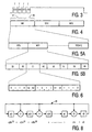
- Figure 4 illustrates a wake-up message WU which comprises a first portion 44 ( Figure 4 ), which is the earlier portion, and a second portion 46, which is the later portion.
- the wake-up message is concatenated with the start of message sequence SOM and the message MES proper.
- FIGs 5A, 5B and 6 illustrate the structure of a wake-up message WU for an individual consumer unit.
- the structure comprises a plurality of concatenated wake-up sequences WS0, WS1 .. WS(N-1).
- Figure 5B illustrates the structure of one example of a wake-up sequence for an individual address.
- the sequence assumes that a 32-bit address is divided into 4 bytes each of 8 bits.
- the wake-up sequence commences with a first 16 bit sync code word SO which is concatenated with a first of the address bytes A3.
- the sequence is completed by alternating second to fourth sync code words S1 to S3 with address bytes A2, A1 and A0 to make a fixed length of 96 bits.
- the address byte A3 is the most significant byte.
- a consumer unit being synchronised with the wake-up signal, if it determines that the address byte A3 is not part of its address, it switches off its receiver section for the remainder of that sequence. Otherwise if byte A3 is accepted, it checks byte A2 and so on so that by the end of the sequence it will have determined whether or not all 4 bytes comprise its address.
- each of the sync code words S0 to S3 include bits identifying the number of the address byte that follows the sync code word.
- Figure 6 illustrates an example of a 16 bit sync code word in which 12 of the bits comprise a fixed pattern and four bits b0 to b3 comprise signalling bits.
- the signalling bits have the meanings tabulated below: Signalling bit Description b1, b0 2-bit number indicating the number of the address byte that follows the synchronisation word.
- b1 is the most significant bit
- b2 Identifies the following addressing mode: 0 - multicast addressing 1 - individual addressing b3 Identifies the first or second portion of the Wakeup. 0 - first part of Wakeup 1 - second part of Wakeup
- Bits b1, b0 identify the transmitted address byte appended to the sync code word so that the processor 12 can determine which of the bits of its address are to be compared with the bits in the received address byte.
- a consumer unit CU determines from the bit b3 in the sync code word that identification of its address has occurred during the first portion 44 ( Figure 4 ) of the wake-up message WU, it resumes the sampling strategy in order to save battery power until the consumer unit CU determines from the change in value of the bit b3 that it is now receiving signals in the second portion 46 ( Figure 4 ), in which case the receiver section of the consumer unit CU remains continuously energised to receive the start of message sequence SOM.
- block 50 indicates energising the receiver section of a consumer unit for a short time period in order to detect carrier.
- Block 52 relates to checking if carrier has been detected. If the answer is no (N), the process returns to the block 50. If carrier has been detected (Y), then in block 54 the receiver remains energised to detect the wake-up message. In block 56 a check is made to see if the wake-up message has been detected. If the answer is no (N), the flow chart reverts to the block 50.
- Block 68 relates to the receiver receiving the start of message sequence SOM and the concatenated message MES.
- Block 70 represents the consumer unit responding to the message and reverting to a sleep mode. The flow chart reverts to the block 50.
- the four bytes A3 to A0 of the address should have approximately random properties in order to maximise the chance that the consumer unit is able to reject the address being transmitted after receiving only one of the address bytes.
- Each byte may take one of 256 different values.
- the address may be mapped onto a randomised address for use in the wake-up message WU. If the randomisation is successful, then in 255 out of 256 cases the wake-up address byte will not match that of the receiving consumer unit, and the consumer unit can reject the address after having seen one byte out of four.
- Figure 8 illustrates performing random mapping using a 32 bit linear feedback shift register 48 with a generator polynomial which is configured to generate a maximal length pseudo-random sequence or M-sequence.
- the 32 bit radio address is loaded in parallel into the stages a0 to a31 of the shift register 48 which is clocked 32 times to give a randomised address.
- generator polynomial represented in hex
- the contents of the shift register cycles through all 2 r - 1 non-zero r-bit numbers.
- the order in which these numbers appear in the shift register depends on the generator polynomial and may be approximately random.
- a31, a30 ... a0 are address bits with a31 being the most significant bit and c32, c31 ... c0 are coefficients of the generator polynomial.
- the scrambled address is the new contents of the shift register and are read-out in parallel.
- Using a linear feedback shift register with a generator polynomial gives a high degree of randomisation and a unique mapping of the radio address.
- the shift register 48 can be clocked by less than the number of bits in the radio address, clocking the shift register by at least the number of bits in the radio address ensures that all the bits contribute to the randomising operation.
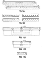
- Figures 9A and 9B illustrates a randomisation scheme in which the least significant bits of the address are distributed evenly the different parts of the scrambled address.
- Figure 9A represents the unscrambled 4 bytes of the radio address and Figure 9B represents 4 bytes of scrambled address, each byte containing 2 bits from each byte of the unscrambled address shown in Figure 9A .
- the most significant bits of the addresses will be the same for all of the consumer units.
- the least significant bits provide a way of differentiating between the consumer units. Therefore in this scheme it is important that each byte of a scrambled address contains some of the least significant bits.
- Figures 10A, 10B and 10C illustrate randomising bits by exclusive - OR (XOR) folding.
- Figure 10A illustrates the unscrambled address about a central fold line FL1.
- the address bits in corresponding bit positions on either side of the fold line FL1 are combined by XOR operations and the result is shown in Figure 9B .
- b0 a16 ⁇ a15
- b7 a23 ⁇ a8
- b8 a24 ⁇ a7
- b15 a31 ⁇ a0
- Figure 10B includes a central fold line FL2 and the bits in corresponding bit positions on either side of the fold line FL2 are combined by XOR operations and the result is shown in Figure 10C which shows one byte of the scrambled address.
- c0 b7 ⁇ b8
- c7 b0 ⁇ b15
- Radio telemetry systems such as remote automatic meter reading systems.
Landscapes
- Engineering & Computer Science (AREA)
- Computer Networks & Wireless Communication (AREA)
- Signal Processing (AREA)
- Mobile Radio Communication Systems (AREA)
Claims (17)
- Verfahren zum Reduzieren des Batteriestromverbrauchs in einem Kommunikationssystem mit einer Sendestation und einer Empfangsstation, die einen Funkidentitätscode bestehend aus M Bits aufweisen, gekennzeichnet durch Aussenden einer Aufweck-Nachricht mit mindestens zwei Wiederholungen einer Aufweckfolge, welche Aufweckfolge N verkettete Teile enthält, wobei N eine ganze Zahl ist, jedes der N Teile ein Synchronisiercodewort und eine unterschiedliche Fraktion M/N von Bits eines Funkidentitätscodes enthält,
durch intermittierendes Einschalten der Empfangsstation, um mindestens eines der Teile zu erkennen, wobei die Empfangsstation im eingeschalteten Zustand gehalten wird und das mindestens eine der Teile analysiert, und
durch Abschalten der Empfangsstation abhängig von der Feststellung, dass die empfangenen Bits des Funkidentitätscodes nicht mit den entsprechenden Bits des Funkidentitätscodes der Empfangsstation übereinstimmen. - Verfahren nach Anspruch 1, dadurch gekennzeichnet, dass die Bits des Funkidentitätscodes vor der Aufteilung randomisiert werden.
- Verfahren nach Anspruch 1 oder 2, dadurch gekennzeichnet, dass jedem der N Teile ein unterschiedliches Synchronisiercodewort vorangestellt ist.
- Verfahren nach einem oder mehreren der Ansprüche 1 bis 3, dadurch gekennzeichnet, dass die Aufweck-Nachricht einen früher übertragenen Abschnitt und einen später übertragenen Abschnitt enthält, dass jedes der Synchronisiercodeworte kennzeichnende Angaben darüber enthält, in welchem der früheren oder späteren Abschnitte es enthalten ist, und dass abhängig davon, ob eine Empfangsstation ihren Funkidentitätscode in dem früheren Abschnitt erkennt, sie fortfährt, mindestens ihren Empfänger weiter intermittierend eingeschaltet zu lassen bis der spätere Abschnitt der übertragenen Aufweck-Nachricht festgestellt wird, wonach ihr Empfänger dauernd eingeschaltet wird, um eine mit der Aufweck-Nachricht verkettete Nachricht zu empfangen.
- Kommunikationssystem mit einer Sendestation und einer Empfangsstation, die einen Funkidentitätscode bestehend aus M Bits aufweisen, dadurch gekennzeichnet
dass die Sendestation Mittel zum Aussenden einer Aufweck-Nachricht mit mindestens zwei Wiederholungen einer Aufweckfolge aufweist, welche Aufweckfolge N verkettete Teile enthält, wobei N eine ganze Zahl ist, jedes der N Teile ein Synchronisiercodewort und eine unterschiedliche Fraktion M/N von Bits eines Funkidentitätscodes enthält,
dass die Empfangsstation Mittel zum intermittierenden Einschalten ihres Empfängers aufweist, um mindestens eines der Teile zu erkennen, zum Halten im eingeschalteten Zustand, um das mindestens eine Teil zu analysieren, und zum Abschalten der Empfangsstation abhängig von der Feststellung, dass die empfangenen Bits des Funkidentitätscodes nicht mit den entsprechenden Bits des Funkidentitätscodes der Empfangsstation übereinstimmen. - System nach Anspruch 5, dadurch gekennzeichnet, dass die Sendestation Mittel zum Randomisieren von Bits des Funkidentitätscodes vor der Aufteilung aufweist.
- System nach Anspruch 6, dadurch gekennzeichnet, dass die Mittel zum Randomisieren von Bits des Funkidentitätscodes ein Schieberegister mit linearer Rückkopplung mit einem Generator-Polynom zum Erzeugen einer M-Folge, Mittel zum Fortschalten des Schieberegisters um eine vorbestimmte Anzahl von Takten und Mittel zum Auslesen der neuen Inhalte des Schieberegisters enthalten.
- System nach Anspruch 5, 6 oder 7, dadurch gekennzeichnet, dass Mittel zum Anhängen eines anderen Synchronisiercodewortes an jedes der N Teile vorgesehen sind.
- System nach einem oder mehreren der Ansprüche 5 bis 8, bei dem die Aufweck-Nachricht einen früher übertragenen Abschnitt und einen später übertragenen Abschnitt enthält, dadurch gekennzeichnet, dass die Sendestation Mittel enthält, in jedes der Synchronisiercodeworte kennzeichnende Angaben darüber einzuschließen, die anzeigen, in welchem der früheren oder späteren Abschnitte das Synchronisiercodewort enthalten ist, und dass in der Empfangsstation Mittel vorgesehen sind, die auf das Erkennen ihres Funkidentitätscodes in dem frühen Abschnitt ansprechen, um mindestens ihren Empfänger weiter intermittierend eingeschaltet zu lassen bis der spätere Abschnitt der übertragenen Aufweck-Nachricht festgestellt wird, wonach das Mittel bewirkt, dass der Empfänger dauernd eingeschaltet wird, um eine mit der Aufweck-Nachricht verkettete Nachricht zu empfangen.
- Sendestation für ein Kommunikationssystem mit einer Empfangsstation, die einen Funkidentitätscode bestehend aus M Bits aufweist, dadurch gekennzeichnet, dass die Sendestation Mittel zum Aussenden einer Aufweck-Nachricht mit mindestens zwei Wiederholungen einer Aufweckfolge aufweist, welche Aufweckfolge N verkettete Teile enthält, wobei N eine ganze Zahl ist, jedes der N Teile ein Synchronisiercodewort und eine unterschiedliche Fraktion M/N von Bits eines Funkidentitätscodes enthält.
- Sendestation nach Anspruch 10, gekennzeichnet durch Mittel zum Randomisieren von Bits des Funkidentitätscodes vor der Aufteilung.
- Sendestation nach Anspruch 10 oder 11, gekennzeichnet durch Mittel zum Anhängen eines anderen Synchronisiercodewortes an jedes der N Teile.
- Sendestation nach einem oder mehreren der Ansprüche 10 bis 12, bei dem die Aufweck-Nachricht einen früher übertragenen Abschnitt und einen später übertragenen Abschnitt enthält, gekennzeichnet durch Mittel zum Einschließen von kennzeichnenden Angaben in jedes der Synchronisiercodeworte, die anzeigen, in welchem der früheren oder späteren Abschnitte das Synchronisiercodewort enthalten ist.
- Empfangsstation für ein Kommunikationssystem mit einer Sendestation und einer Empfangsstation, wobei die Empfangsstation einen Funkidentitätscode bestehend aus M Bits aufweist und die Sendestation Mittel zum Aussenden einer Aufweck-Nachricht mit mindestens zwei Wiederholungen einer Aufweckfolge aufweist, welche Aufweckfolge N verkettete Teile enthält, wobei N eine ganze Zahl ist, jedes der N Teile ein Synchronisiercodewort und eine unterschiedliche
Fraktion M/N von Bits eines Funkidentitätscodes enthält, dadurch gekennzeichnet, dass die Empfangsstation Mittel zum Erkennen des Funkidentitätscodes und Mittel zum intermittierenden Einschalten ihres Empfängers aufweist, um mindestens eines der Teile zu erkennen, zum Halten im eingeschalteten Zustand, um das mindestens eine Teil zu analysieren, und zum Abschalten der Empfangsstation abhängig von der Feststellung, dass die empfangenen Bits des Funkidentitätscodes nicht mit den entsprechenden Bits des Funkidentitätscodes der Empfangsstation übereinstimmen. - Empfangsstation nach Anspruch 14, bei der die Sendestation Mittel zum Randomisieren von Bits des Funkidentitätscodes vor der Aufteilung aufweist, dadurch gekennzeichnet, dass die Mittel zum Erkennen des Funkidentitätscodes mit Mitteln ausgerüstet sind, die erkennen, ob die empfangenen randomisierten Bits den relevanten Bits in dem Empfängeridentitätscode entsprechen.
- Empfangsstation nach Anspruch 14 oder 15, bei der die Sendestation Mittel zum Anhängen eines anderen Synchronisiercodewortes an jedes der N Teile aufweist, dadurch gekennzeichnet, dass die Empfangsstation Mittel zum Identifizieren jedes der Synchronisiercodeworte und zum Anpassen der Mittel zum Erkennen des Funkidentitätscodes aufweist, damit diese die Bits des mit dem bestimmten Synchronisiercodewort verketteten Funkidentitätscodes erkennen.
- Empfangsstation nach Anspruch 14, 15 oder 16, bei der die Aufweck-Nachricht einen früher übertragenen Abschnitt und einen später übertragenen Abschnitt enthält, bei der jedes der Synchronisiercodeworte kennzeichnende Angaben darüber enthält, in welchem der früheren oder späteren Abschnitte das Synchronisiercodewort enthalten ist, dadurch gekennzeichnet, dass die Empfangsstation Mittel aufweist, die beim Erkennen ihres Funkidentitätscodes in dem früheren Abschnitt ansprechen, um mindestens ihren Empfänger intermittierend eingeschaltet zu lassen bis der spätere Abschnitt der übertragenen Aufweck-Nachricht festgestellt wird, wonach das Mittel bewirkt, dass der Empfänger dauernd eingeschaltet wird, um in der Lage zu sein, eine mit der Aufweck-Nachricht verkettete Nachricht zu empfangen.
Applications Claiming Priority (3)
| Application Number | Priority Date | Filing Date | Title |
|---|---|---|---|
| GB9723743 | 1997-11-12 | ||
| GBGB9723743.2A GB9723743D0 (en) | 1997-11-12 | 1997-11-12 | Battery economising in a communications system |
| PCT/IB1998/001790 WO1999025051A2 (en) | 1997-11-12 | 1998-11-09 | Battery economising in a communications system |
Publications (2)
| Publication Number | Publication Date |
|---|---|
| EP0981850A2 EP0981850A2 (de) | 2000-03-01 |
| EP0981850B1 true EP0981850B1 (de) | 2008-09-10 |
Family
ID=10821860
Family Applications (1)
| Application Number | Title | Priority Date | Filing Date |
|---|---|---|---|
| EP98950262A Expired - Lifetime EP0981850B1 (de) | 1997-11-12 | 1998-11-09 | Batteriesparen in einem kommunikationssystem |
Country Status (9)
| Country | Link |
|---|---|
| US (1) | US6239690B1 (de) |
| EP (1) | EP0981850B1 (de) |
| JP (1) | JP4115541B2 (de) |
| KR (1) | KR100703910B1 (de) |
| CN (1) | CN1126381C (de) |
| DE (1) | DE69839991D1 (de) |
| GB (1) | GB9723743D0 (de) |
| TW (1) | TW401660B (de) |
| WO (1) | WO1999025051A2 (de) |
Families Citing this family (76)
| Publication number | Priority date | Publication date | Assignee | Title |
|---|---|---|---|---|
| EP1069265A3 (de) * | 1999-07-01 | 2004-01-21 | Siemens Aktiengesellschaft | Zugangskontrolleinrichtung sowie Zugangskontroll- und Fahrberechtigungseinrichtung |
| GB9920615D0 (en) | 1999-09-02 | 1999-11-03 | Koninkl Philips Electronics Nv | Battery economising in a communications system |
| GB0013147D0 (en) | 2000-05-31 | 2000-07-19 | Koninkl Philips Electronics Nv | Method of and receiver for estimating the bit rate of data |
| GB0022632D0 (en) * | 2000-09-15 | 2000-11-01 | Koninkl Philips Electronics Nv | Method of, and signalling system for, transferring data |
| FR2826485B1 (fr) * | 2001-06-22 | 2006-03-10 | Tekelec Temex | Procede et systeme pour augmenter l'autonomie d'un dispositif emetteur-recepteur radio, et dispositif emetteur-recepteur radio de grande autonomie |
| JP3596490B2 (ja) * | 2001-07-16 | 2004-12-02 | 株式会社デンソー | タイヤ空気圧モニタ用受信機 |
| US7339910B2 (en) | 2001-09-25 | 2008-03-04 | Marvell International Ltd. | Power saving in communication terminals |
| US20030117272A1 (en) * | 2001-12-21 | 2003-06-26 | Fegley Robert E. | System and method of silent alarm |
| US20030176195A1 (en) * | 2002-02-13 | 2003-09-18 | Interdigital Technology Corporation | System and method for efficiently detecting the identification of a received signal |
| GB0208449D0 (en) * | 2002-04-10 | 2002-05-22 | Zarlink Semiconductor Ab | Method of saving power in RF devices |
| US8190163B2 (en) * | 2002-08-08 | 2012-05-29 | Qualcomm Incorporated | Methods and apparatus of enhanced coding in multi-user communication systems |
| US7363039B2 (en) | 2002-08-08 | 2008-04-22 | Qualcomm Incorporated | Method of creating and utilizing diversity in multiple carrier communication system |
| US6961595B2 (en) * | 2002-08-08 | 2005-11-01 | Flarion Technologies, Inc. | Methods and apparatus for operating mobile nodes in multiple states |
| JP3876799B2 (ja) * | 2002-09-09 | 2007-02-07 | 株式会社デンソー | タイヤ空気圧監視システム |
| US7445769B2 (en) | 2002-10-31 | 2008-11-04 | Cadbury Adams Usa Llc | Compositions for removing stains from dental surfaces and methods of making and using the same |
| US7389089B1 (en) * | 2002-11-25 | 2008-06-17 | At&T Delaware Intellectual Property, Inc. | Methods to remotely control a wireless unit |
| US7773982B2 (en) * | 2002-11-25 | 2010-08-10 | At&T Intellectual Property, I, L.P. | Methods, systems and storage media to remotely control a wireless unit |
| US7411895B2 (en) * | 2003-02-19 | 2008-08-12 | Qualcomm Incorporated | Controlled superposition coding in multi-user communication systems |
| US8593932B2 (en) * | 2003-05-16 | 2013-11-26 | Qualcomm Incorporated | Efficient signal transmission methods and apparatus using a shared transmission resource |
| US7390518B2 (en) | 2003-07-11 | 2008-06-24 | Cadbury Adams Usa, Llc | Stain removing chewing gum composition |
| US7925291B2 (en) * | 2003-08-13 | 2011-04-12 | Qualcomm Incorporated | User specific downlink power control channel Q-bit |
| US8591974B2 (en) | 2003-11-21 | 2013-11-26 | Kraft Foods Global Brands Llc | Delivery system for two or more active components as part of an edible composition |
| US8389031B2 (en) | 2005-05-23 | 2013-03-05 | Kraft Foods Global Brands Llc | Coated delivery system for active components as part of an edible composition |
| US8597703B2 (en) | 2005-05-23 | 2013-12-03 | Kraft Foods Global Brands Llc | Delivery system for active components as part of an edible composition including a ratio of encapsulating material and active component |
| US20050112236A1 (en) | 2003-11-21 | 2005-05-26 | Navroz Boghani | Delivery system for active components as part of an edible composition having preselected tensile strength |
| US8389032B2 (en) | 2005-05-23 | 2013-03-05 | Kraft Foods Global Brands Llc | Delivery system for active components as part of an edible composition having selected particle size |
| US8591972B2 (en) | 2005-05-23 | 2013-11-26 | Kraft Foods Global Brands Llc | Delivery system for coated active components as part of an edible composition |
| US8591968B2 (en) | 2005-05-23 | 2013-11-26 | Kraft Foods Global Brands Llc | Edible composition including a delivery system for active components |
| US9271904B2 (en) | 2003-11-21 | 2016-03-01 | Intercontinental Great Brands Llc | Controlled release oral delivery systems |
| US8591973B2 (en) | 2005-05-23 | 2013-11-26 | Kraft Foods Global Brands Llc | Delivery system for active components and a material having preselected hydrophobicity as part of an edible composition |
| US7231233B2 (en) * | 2003-11-25 | 2007-06-12 | G Squared, Llc | Combined multi-media and in ear monitoring system and method of remote monitoring and control thereof |
| EP1692883B1 (de) * | 2003-12-09 | 2010-06-02 | Intelleflex Corporation | Batterieaktivierungsschaltung |
| US7142107B2 (en) | 2004-05-27 | 2006-11-28 | Lawrence Kates | Wireless sensor unit |
| US20060024245A1 (en) * | 2004-07-29 | 2006-02-02 | Cadbury Adams, Llc. | Tooth whitening compositions and delivery systems therefor |
| US7955630B2 (en) | 2004-09-30 | 2011-06-07 | Kraft Foods Global Brands Llc | Thermally stable, high tensile strength encapsulated actives |
| US9198448B2 (en) | 2005-02-07 | 2015-12-01 | Intercontinental Great Brands Llc | Stable tooth whitening gum with reactive ingredients |
| US7604178B2 (en) * | 2005-05-11 | 2009-10-20 | Intelleflex Corporation | Smart tag activation |
| EP1905200A1 (de) | 2005-07-01 | 2008-04-02 | Terahop Networks, Inc. | Nichtdeterministisches und deterministisches netzwerk-routing |
| US8248211B2 (en) | 2005-07-20 | 2012-08-21 | Intelleflex Corporation | Selective RF device activation |
| US8548098B2 (en) | 2005-12-15 | 2013-10-01 | Intelleflex Corporation | Clock-free activation circuit |
| US8755313B2 (en) | 2007-01-11 | 2014-06-17 | Qualcomm Incorporated | Using DTX and DRX in a wireless communication system |
| US8018885B2 (en) * | 2008-02-04 | 2011-09-13 | Sony Ericsson Mobile Communications Ab | Code keying in a power savings mode |
| WO2009151877A2 (en) | 2008-05-16 | 2009-12-17 | Terahop Networks, Inc. | Systems and apparatus for securing a container |
| US8391435B2 (en) | 2008-12-25 | 2013-03-05 | Google Inc. | Receiver state estimation in a duty cycled radio |
| US9451541B2 (en) * | 2012-01-11 | 2016-09-20 | Shenzhen Hac Telecom Technology Co., Ltd. | System and method for wireless communication |
| WO2014100272A1 (en) * | 2012-12-19 | 2014-06-26 | Exxonmobil Upstream Research Company | Apparatus and method for monitoring fluid flow in a wellbore using acoustic signals |
| US9759062B2 (en) * | 2012-12-19 | 2017-09-12 | Exxonmobil Upstream Research Company | Telemetry system for wireless electro-acoustical transmission of data along a wellbore |
| US9765562B2 (en) * | 2014-05-07 | 2017-09-19 | Vivint, Inc. | Weather based notification systems and methods for home automation |
| CA2955381C (en) | 2014-09-12 | 2022-03-22 | Exxonmobil Upstream Research Company | Discrete wellbore devices, hydrocarbon wells including a downhole communication network and the discrete wellbore devices and systems and methods including the same |
| US10408047B2 (en) | 2015-01-26 | 2019-09-10 | Exxonmobil Upstream Research Company | Real-time well surveillance using a wireless network and an in-wellbore tool |
| CN105185071B (zh) * | 2015-05-21 | 2018-11-20 | 成都康伟力创科技有限公司 | 燃气表远程抄表网络数据交换方法 |
| US10465505B2 (en) | 2016-08-30 | 2019-11-05 | Exxonmobil Upstream Research Company | Reservoir formation characterization using a downhole wireless network |
| US10526888B2 (en) | 2016-08-30 | 2020-01-07 | Exxonmobil Upstream Research Company | Downhole multiphase flow sensing methods |
| US10697287B2 (en) | 2016-08-30 | 2020-06-30 | Exxonmobil Upstream Research Company | Plunger lift monitoring via a downhole wireless network field |
| US10344583B2 (en) | 2016-08-30 | 2019-07-09 | Exxonmobil Upstream Research Company | Acoustic housing for tubulars |
| US10487647B2 (en) | 2016-08-30 | 2019-11-26 | Exxonmobil Upstream Research Company | Hybrid downhole acoustic wireless network |
| US10590759B2 (en) | 2016-08-30 | 2020-03-17 | Exxonmobil Upstream Research Company | Zonal isolation devices including sensing and wireless telemetry and methods of utilizing the same |
| US10415376B2 (en) | 2016-08-30 | 2019-09-17 | Exxonmobil Upstream Research Company | Dual transducer communications node for downhole acoustic wireless networks and method employing same |
| US10364669B2 (en) | 2016-08-30 | 2019-07-30 | Exxonmobil Upstream Research Company | Methods of acoustically communicating and wells that utilize the methods |
| US10697288B2 (en) | 2017-10-13 | 2020-06-30 | Exxonmobil Upstream Research Company | Dual transducer communications node including piezo pre-tensioning for acoustic wireless networks and method employing same |
| US11035226B2 (en) | 2017-10-13 | 2021-06-15 | Exxomobil Upstream Research Company | Method and system for performing operations with communications |
| AU2018347876B2 (en) | 2017-10-13 | 2021-10-07 | Exxonmobil Upstream Research Company | Method and system for performing hydrocarbon operations with mixed communication networks |
| US10837276B2 (en) | 2017-10-13 | 2020-11-17 | Exxonmobil Upstream Research Company | Method and system for performing wireless ultrasonic communications along a drilling string |
| WO2019074657A1 (en) | 2017-10-13 | 2019-04-18 | Exxonmobil Upstream Research Company | METHOD AND SYSTEM FOR REALIZING OPERATIONS USING COMMUNICATIONS |
| AU2018347465B2 (en) | 2017-10-13 | 2021-10-07 | Exxonmobil Upstream Research Company | Method and system for performing communications using aliasing |
| US10690794B2 (en) | 2017-11-17 | 2020-06-23 | Exxonmobil Upstream Research Company | Method and system for performing operations using communications for a hydrocarbon system |
| US12000273B2 (en) | 2017-11-17 | 2024-06-04 | ExxonMobil Technology and Engineering Company | Method and system for performing hydrocarbon operations using communications associated with completions |
| AU2018367388C1 (en) | 2017-11-17 | 2022-04-14 | Exxonmobil Upstream Research Company | Method and system for performing wireless ultrasonic communications along tubular members |
| US10844708B2 (en) | 2017-12-20 | 2020-11-24 | Exxonmobil Upstream Research Company | Energy efficient method of retrieving wireless networked sensor data |
| US11156081B2 (en) | 2017-12-29 | 2021-10-26 | Exxonmobil Upstream Research Company | Methods and systems for operating and maintaining a downhole wireless network |
| MX2020005766A (es) | 2017-12-29 | 2020-08-20 | Exxonmobil Upstream Res Co | Metodos y sistemas para monitorear y optimizar las operaciones de estimulacion de yacimientos. |
| CA3090799C (en) | 2018-02-08 | 2023-10-10 | Exxonmobil Upstream Research Company | Methods of network peer identification and self-organization using unique tonal signatures and wells that use the methods |
| US11268378B2 (en) | 2018-02-09 | 2022-03-08 | Exxonmobil Upstream Research Company | Downhole wireless communication node and sensor/tools interface |
| CN110972236B (zh) * | 2018-09-27 | 2022-04-08 | 大唐移动通信设备有限公司 | 一种节能信号传输方法、终端和网络侧设备 |
| US11952886B2 (en) | 2018-12-19 | 2024-04-09 | ExxonMobil Technology and Engineering Company | Method and system for monitoring sand production through acoustic wireless sensor network |
| US11293280B2 (en) | 2018-12-19 | 2022-04-05 | Exxonmobil Upstream Research Company | Method and system for monitoring post-stimulation operations through acoustic wireless sensor network |
Family Cites Families (3)
| Publication number | Priority date | Publication date | Assignee | Title |
|---|---|---|---|---|
| CA2000683C (en) | 1988-12-01 | 1993-04-13 | Walter Lee Davis | Power conservation method and apparatus for a portion of a predetermined signal |
| GB9202249D0 (en) | 1992-02-03 | 1992-03-18 | Philips Electronics Uk Ltd | Battery power conservation in a selective call system |
| GB9311380D0 (en) * | 1993-06-02 | 1993-07-21 | Philips Electronics Uk Ltd | A selective call system |
-
1997
- 1997-11-12 GB GBGB9723743.2A patent/GB9723743D0/en not_active Ceased
-
1998
- 1998-11-09 CN CN98803324A patent/CN1126381C/zh not_active Expired - Fee Related
- 1998-11-09 JP JP52584199A patent/JP4115541B2/ja not_active Expired - Fee Related
- 1998-11-09 EP EP98950262A patent/EP0981850B1/de not_active Expired - Lifetime
- 1998-11-09 KR KR1019997006242A patent/KR100703910B1/ko not_active Expired - Fee Related
- 1998-11-09 US US09/188,750 patent/US6239690B1/en not_active Expired - Lifetime
- 1998-11-09 WO PCT/IB1998/001790 patent/WO1999025051A2/en not_active Ceased
- 1998-11-09 DE DE69839991T patent/DE69839991D1/de not_active Expired - Lifetime
- 1998-11-11 TW TW087118785A patent/TW401660B/zh not_active IP Right Cessation
Also Published As
| Publication number | Publication date |
|---|---|
| WO1999025051A2 (en) | 1999-05-20 |
| JP2001508274A (ja) | 2001-06-19 |
| JP4115541B2 (ja) | 2008-07-09 |
| DE69839991D1 (de) | 2008-10-23 |
| GB9723743D0 (en) | 1998-01-07 |
| WO1999025051A3 (en) | 1999-07-29 |
| CN1126381C (zh) | 2003-10-29 |
| KR100703910B1 (ko) | 2007-04-05 |
| KR20000070023A (ko) | 2000-11-25 |
| US6239690B1 (en) | 2001-05-29 |
| EP0981850A2 (de) | 2000-03-01 |
| TW401660B (en) | 2000-08-11 |
| CN1250577A (zh) | 2000-04-12 |
Similar Documents
| Publication | Publication Date | Title |
|---|---|---|
| US6239690B1 (en) | Battery economizing in a communications system | |
| US7292868B2 (en) | Apparatus and method for use in paging mode in wireless communications systems | |
| US5752202A (en) | Method of message delivery adapted for a power conservation system | |
| JP3163070B2 (ja) | 基地局から端末装置へ情報を送信する方法、基地局、及び端末装置 | |
| AU712892B2 (en) | Method for reducing power consumption in portable radiotelephones | |
| US5566366A (en) | Method of power conservation in a data communications system | |
| US7231221B2 (en) | Channel access methods and apparatus in low-power wireless communication systems | |
| CA2181046C (en) | Apparatus for energy conservation in a communication system | |
| US5459457A (en) | Paging or other selective call system with battery power conservation | |
| US20030031140A1 (en) | Method and apparatus for extending communication unit battery life | |
| US6119024A (en) | Mobile radio system | |
| KR20000069556A (ko) | 이동 전화기를 위한 감소된 전력 슬립 모드 | |
| EP1459584B1 (de) | Zuverlässige dekodierung eines schnellen funkrufkanals | |
| HK1006906B (en) | Battery power conservation in a selective call system | |
| JP3755845B2 (ja) | 無線電話 | |
| JP3139705B2 (ja) | Cdma通信方法、cdma通信システム、これに用いる送信機及び受信機 | |
| Mangione-Smith | Low power communications protocols: paging and beyond | |
| US5850186A (en) | Method of receiving radio paging signal | |
| US5414419A (en) | Battery saving method for selective call receivers | |
| US5550829A (en) | Method for reallocation frame assignments of receives in a communication system | |
| US5452472A (en) | Radio communication receiving device detecting a frequency modulation preamble signal | |
| EP1127415B1 (de) | Batterieeinsparung in einem Kommunikationssystem | |
| JP3695873B2 (ja) | 無線システム | |
| KR100532316B1 (ko) | 방송서비스에서의 단말기 배터리 소모 감소방법 | |
| JPH0496529A (ja) | 無線呼出しシステムのバッテリーセーブ方法 |
Legal Events
| Date | Code | Title | Description |
|---|---|---|---|
| PUAI | Public reference made under article 153(3) epc to a published international application that has entered the european phase |
Free format text: ORIGINAL CODE: 0009012 |
|
| 17P | Request for examination filed |
Effective date: 19990812 |
|
| AK | Designated contracting states |
Kind code of ref document: A2 Designated state(s): CH DE ES FR GB IT LI |
|
| RAP1 | Party data changed (applicant data changed or rights of an application transferred) |
Owner name: NXP B.V. |
|
| GRAP | Despatch of communication of intention to grant a patent |
Free format text: ORIGINAL CODE: EPIDOSNIGR1 |
|
| RIC1 | Information provided on ipc code assigned before grant |
Ipc: H04Q 7/18 20060101AFI20080304BHEP |
|
| GRAS | Grant fee paid |
Free format text: ORIGINAL CODE: EPIDOSNIGR3 |
|
| GRAA | (expected) grant |
Free format text: ORIGINAL CODE: 0009210 |
|
| AK | Designated contracting states |
Kind code of ref document: B1 Designated state(s): CH DE ES FR GB IT LI |
|
| REG | Reference to a national code |
Ref country code: GB Ref legal event code: FG4D |
|
| REG | Reference to a national code |
Ref country code: CH Ref legal event code: EP |
|
| REF | Corresponds to: |
Ref document number: 69839991 Country of ref document: DE Date of ref document: 20081023 Kind code of ref document: P |
|
| PG25 | Lapsed in a contracting state [announced via postgrant information from national office to epo] |
Ref country code: ES Free format text: LAPSE BECAUSE OF FAILURE TO SUBMIT A TRANSLATION OF THE DESCRIPTION OR TO PAY THE FEE WITHIN THE PRESCRIBED TIME-LIMIT Effective date: 20081221 |
|
| REG | Reference to a national code |
Ref country code: CH Ref legal event code: PL |
|
| PLBE | No opposition filed within time limit |
Free format text: ORIGINAL CODE: 0009261 |
|
| STAA | Information on the status of an ep patent application or granted ep patent |
Free format text: STATUS: NO OPPOSITION FILED WITHIN TIME LIMIT |
|
| 26N | No opposition filed |
Effective date: 20090611 |
|
| PG25 | Lapsed in a contracting state [announced via postgrant information from national office to epo] |
Ref country code: IT Free format text: LAPSE BECAUSE OF FAILURE TO SUBMIT A TRANSLATION OF THE DESCRIPTION OR TO PAY THE FEE WITHIN THE PRESCRIBED TIME-LIMIT Effective date: 20080910 |
|
| PG25 | Lapsed in a contracting state [announced via postgrant information from national office to epo] |
Ref country code: LI Free format text: LAPSE BECAUSE OF NON-PAYMENT OF DUE FEES Effective date: 20081130 Ref country code: CH Free format text: LAPSE BECAUSE OF NON-PAYMENT OF DUE FEES Effective date: 20081130 |
|
| PGFP | Annual fee paid to national office [announced via postgrant information from national office to epo] |
Ref country code: GB Payment date: 20101026 Year of fee payment: 13 |
|
| PGFP | Annual fee paid to national office [announced via postgrant information from national office to epo] |
Ref country code: FR Payment date: 20111205 Year of fee payment: 14 |
|
| GBPC | Gb: european patent ceased through non-payment of renewal fee |
Effective date: 20121109 |
|
| REG | Reference to a national code |
Ref country code: FR Ref legal event code: ST Effective date: 20130731 |
|
| PG25 | Lapsed in a contracting state [announced via postgrant information from national office to epo] |
Ref country code: FR Free format text: LAPSE BECAUSE OF NON-PAYMENT OF DUE FEES Effective date: 20121130 Ref country code: GB Free format text: LAPSE BECAUSE OF NON-PAYMENT OF DUE FEES Effective date: 20121109 |
|
| PGFP | Annual fee paid to national office [announced via postgrant information from national office to epo] |
Ref country code: DE Payment date: 20161020 Year of fee payment: 19 |
|
| REG | Reference to a national code |
Ref country code: DE Ref legal event code: R081 Ref document number: 69839991 Country of ref document: DE Owner name: OCT CIRCUIT TECHNOLOGIES INTERNATIONAL LTD., IE Free format text: FORMER OWNER: NXP B.V., EINDHOVEN, NL |
|
| REG | Reference to a national code |
Ref country code: DE Ref legal event code: R119 Ref document number: 69839991 Country of ref document: DE |
|
| PG25 | Lapsed in a contracting state [announced via postgrant information from national office to epo] |
Ref country code: DE Free format text: LAPSE BECAUSE OF NON-PAYMENT OF DUE FEES Effective date: 20180602 |