EP0980748A1 - Vorrichtung zum Verbinden eines Aufreiss-Streifens mit eine Folie - Google Patents
Vorrichtung zum Verbinden eines Aufreiss-Streifens mit eine Folie Download PDFInfo
- Publication number
- EP0980748A1 EP0980748A1 EP99111719A EP99111719A EP0980748A1 EP 0980748 A1 EP0980748 A1 EP 0980748A1 EP 99111719 A EP99111719 A EP 99111719A EP 99111719 A EP99111719 A EP 99111719A EP 0980748 A1 EP0980748 A1 EP 0980748A1
- Authority
- EP
- European Patent Office
- Prior art keywords
- strip
- web
- path
- belt
- along
- Prior art date
- Legal status (The legal status is an assumption and is not a legal conclusion. Google has not performed a legal analysis and makes no representation as to the accuracy of the status listed.)
- Withdrawn
Links
Images

Classifications
-
- B—PERFORMING OPERATIONS; TRANSPORTING
- B29—WORKING OF PLASTICS; WORKING OF SUBSTANCES IN A PLASTIC STATE IN GENERAL
- B29C—SHAPING OR JOINING OF PLASTICS; SHAPING OF MATERIAL IN A PLASTIC STATE, NOT OTHERWISE PROVIDED FOR; AFTER-TREATMENT OF THE SHAPED PRODUCTS, e.g. REPAIRING
- B29C65/00—Joining or sealing of preformed parts, e.g. welding of plastics materials; Apparatus therefor
- B29C65/02—Joining or sealing of preformed parts, e.g. welding of plastics materials; Apparatus therefor by heating, with or without pressure
- B29C65/18—Joining or sealing of preformed parts, e.g. welding of plastics materials; Apparatus therefor by heating, with or without pressure using heated tools
- B29C65/24—Joining or sealing of preformed parts, e.g. welding of plastics materials; Apparatus therefor by heating, with or without pressure using heated tools characterised by the means for heating the tool
- B29C65/30—Electrical means
- B29C65/32—Induction
-
- B—PERFORMING OPERATIONS; TRANSPORTING
- B29—WORKING OF PLASTICS; WORKING OF SUBSTANCES IN A PLASTIC STATE IN GENERAL
- B29C—SHAPING OR JOINING OF PLASTICS; SHAPING OF MATERIAL IN A PLASTIC STATE, NOT OTHERWISE PROVIDED FOR; AFTER-TREATMENT OF THE SHAPED PRODUCTS, e.g. REPAIRING
- B29C65/00—Joining or sealing of preformed parts, e.g. welding of plastics materials; Apparatus therefor
- B29C65/02—Joining or sealing of preformed parts, e.g. welding of plastics materials; Apparatus therefor by heating, with or without pressure
- B29C65/18—Joining or sealing of preformed parts, e.g. welding of plastics materials; Apparatus therefor by heating, with or without pressure using heated tools
-
- B—PERFORMING OPERATIONS; TRANSPORTING
- B29—WORKING OF PLASTICS; WORKING OF SUBSTANCES IN A PLASTIC STATE IN GENERAL
- B29C—SHAPING OR JOINING OF PLASTICS; SHAPING OF MATERIAL IN A PLASTIC STATE, NOT OTHERWISE PROVIDED FOR; AFTER-TREATMENT OF THE SHAPED PRODUCTS, e.g. REPAIRING
- B29C66/00—General aspects of processes or apparatus for joining preformed parts
- B29C66/01—General aspects dealing with the joint area or with the area to be joined
- B29C66/05—Particular design of joint configurations
- B29C66/10—Particular design of joint configurations particular design of the joint cross-sections
- B29C66/11—Joint cross-sections comprising a single joint-segment, i.e. one of the parts to be joined comprising a single joint-segment in the joint cross-section
- B29C66/112—Single lapped joints
- B29C66/1122—Single lap to lap joints, i.e. overlap joints
-
- B—PERFORMING OPERATIONS; TRANSPORTING
- B29—WORKING OF PLASTICS; WORKING OF SUBSTANCES IN A PLASTIC STATE IN GENERAL
- B29C—SHAPING OR JOINING OF PLASTICS; SHAPING OF MATERIAL IN A PLASTIC STATE, NOT OTHERWISE PROVIDED FOR; AFTER-TREATMENT OF THE SHAPED PRODUCTS, e.g. REPAIRING
- B29C66/00—General aspects of processes or apparatus for joining preformed parts
- B29C66/40—General aspects of joining substantially flat articles, e.g. plates, sheets or web-like materials; Making flat seams in tubular or hollow articles; Joining single elements to substantially flat surfaces
- B29C66/47—Joining single elements to sheets, plates or other substantially flat surfaces
- B29C66/472—Joining single elements to sheets, plates or other substantially flat surfaces said single elements being substantially flat
- B29C66/4722—Fixing strips to surfaces other than edge faces
-
- B—PERFORMING OPERATIONS; TRANSPORTING
- B29—WORKING OF PLASTICS; WORKING OF SUBSTANCES IN A PLASTIC STATE IN GENERAL
- B29C—SHAPING OR JOINING OF PLASTICS; SHAPING OF MATERIAL IN A PLASTIC STATE, NOT OTHERWISE PROVIDED FOR; AFTER-TREATMENT OF THE SHAPED PRODUCTS, e.g. REPAIRING
- B29C66/00—General aspects of processes or apparatus for joining preformed parts
- B29C66/80—General aspects of machine operations or constructions and parts thereof
- B29C66/81—General aspects of the pressing elements, i.e. the elements applying pressure on the parts to be joined in the area to be joined, e.g. the welding jaws or clamps
- B29C66/814—General aspects of the pressing elements, i.e. the elements applying pressure on the parts to be joined in the area to be joined, e.g. the welding jaws or clamps characterised by the design of the pressing elements, e.g. of the welding jaws or clamps
- B29C66/8145—General aspects of the pressing elements, i.e. the elements applying pressure on the parts to be joined in the area to be joined, e.g. the welding jaws or clamps characterised by the design of the pressing elements, e.g. of the welding jaws or clamps characterised by the constructional aspects of the pressing elements, e.g. of the welding jaws or clamps
- B29C66/81461—General aspects of the pressing elements, i.e. the elements applying pressure on the parts to be joined in the area to be joined, e.g. the welding jaws or clamps characterised by the design of the pressing elements, e.g. of the welding jaws or clamps characterised by the constructional aspects of the pressing elements, e.g. of the welding jaws or clamps being multi-lamellar or segmented, i.e. comprising a plurality of strips, plates or stacked elements
-
- B—PERFORMING OPERATIONS; TRANSPORTING
- B29—WORKING OF PLASTICS; WORKING OF SUBSTANCES IN A PLASTIC STATE IN GENERAL
- B29C—SHAPING OR JOINING OF PLASTICS; SHAPING OF MATERIAL IN A PLASTIC STATE, NOT OTHERWISE PROVIDED FOR; AFTER-TREATMENT OF THE SHAPED PRODUCTS, e.g. REPAIRING
- B29C66/00—General aspects of processes or apparatus for joining preformed parts
- B29C66/80—General aspects of machine operations or constructions and parts thereof
- B29C66/81—General aspects of the pressing elements, i.e. the elements applying pressure on the parts to be joined in the area to be joined, e.g. the welding jaws or clamps
- B29C66/814—General aspects of the pressing elements, i.e. the elements applying pressure on the parts to be joined in the area to be joined, e.g. the welding jaws or clamps characterised by the design of the pressing elements, e.g. of the welding jaws or clamps
- B29C66/8145—General aspects of the pressing elements, i.e. the elements applying pressure on the parts to be joined in the area to be joined, e.g. the welding jaws or clamps characterised by the design of the pressing elements, e.g. of the welding jaws or clamps characterised by the constructional aspects of the pressing elements, e.g. of the welding jaws or clamps
- B29C66/81463—General aspects of the pressing elements, i.e. the elements applying pressure on the parts to be joined in the area to be joined, e.g. the welding jaws or clamps characterised by the design of the pressing elements, e.g. of the welding jaws or clamps characterised by the constructional aspects of the pressing elements, e.g. of the welding jaws or clamps comprising a plurality of single pressing elements, e.g. a plurality of sonotrodes, or comprising a plurality of single counter-pressing elements, e.g. a plurality of anvils, said plurality of said single elements being suitable for making a single joint
- B29C66/81465—General aspects of the pressing elements, i.e. the elements applying pressure on the parts to be joined in the area to be joined, e.g. the welding jaws or clamps characterised by the design of the pressing elements, e.g. of the welding jaws or clamps characterised by the constructional aspects of the pressing elements, e.g. of the welding jaws or clamps comprising a plurality of single pressing elements, e.g. a plurality of sonotrodes, or comprising a plurality of single counter-pressing elements, e.g. a plurality of anvils, said plurality of said single elements being suitable for making a single joint one placed behind the other in a single row in the feed direction
-
- B—PERFORMING OPERATIONS; TRANSPORTING
- B29—WORKING OF PLASTICS; WORKING OF SUBSTANCES IN A PLASTIC STATE IN GENERAL
- B29C—SHAPING OR JOINING OF PLASTICS; SHAPING OF MATERIAL IN A PLASTIC STATE, NOT OTHERWISE PROVIDED FOR; AFTER-TREATMENT OF THE SHAPED PRODUCTS, e.g. REPAIRING
- B29C66/00—General aspects of processes or apparatus for joining preformed parts
- B29C66/80—General aspects of machine operations or constructions and parts thereof
- B29C66/83—General aspects of machine operations or constructions and parts thereof characterised by the movement of the joining or pressing tools
- B29C66/834—General aspects of machine operations or constructions and parts thereof characterised by the movement of the joining or pressing tools moving with the parts to be joined
- B29C66/8341—Roller, cylinder or drum types; Band or belt types; Ball types
- B29C66/83421—Roller, cylinder or drum types; Band or belt types; Ball types band or belt types
- B29C66/83423—Roller, cylinder or drum types; Band or belt types; Ball types band or belt types cooperating bands or belts
-
- B—PERFORMING OPERATIONS; TRANSPORTING
- B29—WORKING OF PLASTICS; WORKING OF SUBSTANCES IN A PLASTIC STATE IN GENERAL
- B29C—SHAPING OR JOINING OF PLASTICS; SHAPING OF MATERIAL IN A PLASTIC STATE, NOT OTHERWISE PROVIDED FOR; AFTER-TREATMENT OF THE SHAPED PRODUCTS, e.g. REPAIRING
- B29C66/00—General aspects of processes or apparatus for joining preformed parts
- B29C66/01—General aspects dealing with the joint area or with the area to be joined
- B29C66/02—Preparation of the material, in the area to be joined, prior to joining or welding
- B29C66/024—Thermal pre-treatments
- B29C66/0242—Heating, or preheating, e.g. drying
Definitions
- This invention relates to a device for bonding a tear-off strip to a web.
- the invention relates to the bonding of a tear-off strip to a propylene web used for wrapping cigarette packets within an overwrapping machine, to which this description makes explicit reference but without losing its generality on this account.
- the polypropylene is cut into sheets to form a wrapper which is wrapped about the packets to insulate the cigarettes and protect them from external atmospheric conditions, and is opened by the said tear-off strip which, when pulled, separates the wrapper into two portions.
- the tear-off strip is bonded to the polypropylene web by devices provided with guide means common to the web and to the strip in order to guide the strip in contact with the web into a determined position, and with heated rollers about part of which the web and strip pass to achieve partial melting of both the strip and the web in order to intimately join the strip to the web, or in other words to form the bond.
- the contact angle cannot be increased beyond a determined limit depending on the roller diameter.
- the ring temperature cannot be increased because a too sudden temperature change could damage both the web and the strip.
- a solution to the aforesaid drawback could be to increase the diameter of the roller which, however, on the one hand would become extremely heavy to the extent of requiring appropriately designed supports, and on the other hand would assume relatively large overall dimensions.
- the object of this invention is to provide a device for bonding a tear-off strip to a web which ensures an effective bond even when the web and strip advance at high speed.
- the invention provides a device for bonding a tear-off strip to a web, the device comprising first guide means common to the web and to the tear-off strip such that the web and strip extend along a first common path in a position in which the strip is arranged in contact with said web, and at least one bonder positioned along said first path, the device being characterised in that said bonder comprises at least one bonding belt and second guide means to advance said belt and position it substantially in contact with said strip, or with said web in correspondence with said strip, along at least a part of said first path.
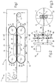
- the reference numeral 1 indicates a device for bonding a tear-off strip 2 to a polypropylene web 3, which is unwound from a reel, not shown, and extends for a determined width between an edge 3a and an edge 3b, to be used to form wrappers of known type, not shown, wrapped about cigarette packets of known type, not shown.
- the strip 2 is unwound from a reel, not shown, and has a negligible width compared with the width of the web 3.
- the device 1 comprises a frame 4, on which an entry roller 5 and an exit roller 6 are mounted, the rollers 5 and 6 being rotatable about respective parallel axes 7 and 8 extending perpendicular to the plane of the sheet of Figure 1.
- the rollers 5 and 6 guide the strip 2 and web 3 in a direction D to define a rectilinear path P for the web 3 and strip 2.
- the path P extends between the rollers 5 and 6, along the said path P the strip 2 being superimposed on the web 3 in a determined position at a determined distance from the edge 3a the web 3.
- the device also comprises a bonder 9 positioned above the path P and a bonder 10 positioned below the path P to form the bond between the tear-off strip 2 and the web 3.
- the bonder 9 comprises a drive pulley 11 and a driven pulley 12, these being rotatable about respective axes 13 and 14 in an anticlockwise direction in Figure 1.
- a belt 15 of substantially circular cross-section passes endlessly about the pulleys 11 and 12.
- Belt 15 is made of a material which can be heated by means of electromagnetic induction, e.g. a ferromagnetic material.
- the belt 15 defines an oblong path P1 having a lower rectilinear portion 16 and an upper rectilinear portion 17 which are joined together by two curved portions 18 and 19.
- the bonder 9 also comprises two induction blocks 20 and 21 arranged in succession above the portion 16 and having two respective electrical windings of known type, not shown, for generating respective magnetic fields which encounter and heat the belt 15.
- the bonder 10 comprises a drive pulley 22 and a driven pulley 23, these being rotatable about respective axes 24 and 25 in a clockwise direction in Figure 1.
- a belt 26 of substantially circular cross-section and constructed of a ferromagnetic material passes endlessly about the pulleys 22 and 23.
- the belt 26 defines an oblong path P2 having an upper rectilinear portion 27 and a lower rectilinear portion 28 which are joined together by two curved portions 29 and 30.
- the belt 26 extends parallel to the path P and is in contact with the web 3 in a region in correspondence with the strip 2. In other words the web 3 and the strip 2 are sandwiched between the belts 15 and 26 along the path P in correspondence with the portion 16 and 27.
- the bonder 10 also comprises two induction blocks 31 and 32 arranged in succession below the portion 27 and having two respective electrical windings of known type, not shown, for generating respective magnetic fields which encounter and heat the belt 26.
- the drive pulleys 11 and 22 of the respective bonders 9 and 10 have a common transmission comprising a motor 34 which rotates a gear wheel 35 rotatable about a respective pin 36 coaxial with the axis 13 and engaging a gear wheel 37 rotatable about a pin 38 coaxial with the axis 24.
- the pins 36 and 38 are supported by respective bearings 39 and 40 mounted on the frame 4 and connect the gear wheels 35 and 37 to the respective pulleys 11 and 12.
- the motor 34 is a variable speed motor to adapt the belt speed to the advancement speed of the web 3 and strip 2.
- a web 3 is guided by the rollers 5 and 6 along the path P in the direction D, a strip 2 being simultaneously guided by the rollers 5 and 6 along the same path P and in the same direction D so as to lie on the web 3 and in contact with the web 3 along the path P as clearly shown in Figure 2 and 3.
- the strip 2 and web 3 extend taut between the rollers 5 and 6 and are sandwiched between the belts 15 and 26, which are heated by means electric current generated in the belts by respective inductors 20, 21 and 31, 32 to obtain temporary partial melting both of the strip 2 and of that portion of the web 3 in contact with the strip 2.
- the belts 15 and 26 are heated along their portions 16 and 27 respectively, these transferring part of the heat to the web 3 and strip 2, whereas the belts 15 and 26 cool along the portions 17, 18 and 19 in the case of the belt 15 and along the portions 28, 29 and 30 in the case of the belt 26.
- the strip 2 and web 3 begin to cool along the path P downstream of the pulleys 11 and 22.
- the heating intensity of the belts 15 and 26 is regulated on the basis of the advancement speed of the strip 2 and web 3, which determines the advancement speed of the belts 15 and 26, and on the basis of the thermal conductivity of the material used to construct the belts 15 and 26.
- the inductors 20 and 21 are set to an intensity which can be varied such as to achieve the required heat transfer between the belts 15, 26 and the strip 2 and web 3.
- the inductors 31 and 32 are omitted, the belt 26 performing only the mechanical function of counteracting the belt 15.
- the bonder 10 is omitted and replaced by a guide 41, which comprises an elongate plate 42 supported by brackets 43 fixed to the frame 4.
- the plate 42 extends parallel to the path P along the portion 16 between the pulleys 11 and 12 and has an upper face 44 provided with bristles 45, which extend substantially upwards and are arranged in contact with the web 3.
- the purpose of the bristles 45 is to support the web 3 along the portion 16 and to counteract the action of the belt 15.
- the bristles have a determined elasticity such as to deform under the thrust of the belt 15. In other words, the bristles 45 urge the web 3 upwards, this then tending to partially wrap about the profile of the belt 15 and also cause the strip 2 to wrap about the same belt 15.
- a motor 46 drives the pulley 11 via a pin 47 coaxial with the axis 13.
- the belt 15 or both belts 15 and 26 can have other than circular cross-sections.
- a triangular cross-section is particularly functional in the case of two counteracting belts 15 and 26 having two parallel faces with a width equal to the width of the strip 2.
Applications Claiming Priority (2)
| Application Number | Priority Date | Filing Date | Title |
|---|---|---|---|
| ITBO980456 | 1998-07-24 | ||
| IT1998BO000456A IT1304457B1 (it) | 1998-07-24 | 1998-07-24 | Dispositivo di saldatura di un nastrino a strappo ad un nastro. |
Publications (1)
| Publication Number | Publication Date |
|---|---|
| EP0980748A1 true EP0980748A1 (de) | 2000-02-23 |
Family
ID=11343328
Family Applications (1)
| Application Number | Title | Priority Date | Filing Date |
|---|---|---|---|
| EP99111719A Withdrawn EP0980748A1 (de) | 1998-07-24 | 1999-06-17 | Vorrichtung zum Verbinden eines Aufreiss-Streifens mit eine Folie |
Country Status (2)
| Country | Link |
|---|---|
| EP (1) | EP0980748A1 (de) |
| IT (1) | IT1304457B1 (de) |
Cited By (1)
| Publication number | Priority date | Publication date | Assignee | Title |
|---|---|---|---|---|
| EP1342551A1 (de) * | 2002-03-05 | 2003-09-10 | M-Tek, Inc. | Heissschweissvorrichtung |
Citations (9)
| Publication number | Priority date | Publication date | Assignee | Title |
|---|---|---|---|---|
| US3236027A (en) * | 1961-05-08 | 1966-02-22 | Schmermund Alfred | Packaging machines |
| US4498939A (en) * | 1983-01-03 | 1985-02-12 | Johnson James R | Method and apparatus for making zipper bags |
| JPS61209134A (ja) * | 1985-03-13 | 1986-09-17 | Kyoraku Co Ltd | ブロ−孔の閉塞方法 |
| DE3611133A1 (de) * | 1986-04-03 | 1987-10-08 | Steuler Industriewerke Gmbh | Verschweissen von thermoplastischen werkstoffen |
| US4746391A (en) * | 1985-11-29 | 1988-05-24 | Hoechst Aktiengesellschaft | Apparatus for continuous welding or sealing of seams of plastic films |
| EP0348945A2 (de) * | 1988-07-01 | 1990-01-03 | H.B. Fuller Company | Verfahren und Vorrichtung zum intermittierenden Aufbringen von Klebebandabschnitten |
| EP0569807A1 (de) * | 1992-05-14 | 1993-11-18 | Focke & Co. (GmbH & Co.) | Vorrichtung zum Verbinden eines Aufreissstreifens mit einer Materialbahn |
| US5505813A (en) * | 1989-07-21 | 1996-04-09 | Kmk Lizence Ltd. | Apparatus and process for the production of tubular bodies |
| US5672234A (en) * | 1995-04-28 | 1997-09-30 | Park-Air Corporation | Zipper fusing machine for attaching zipper material to a plastic web |
-
1998
- 1998-07-24 IT IT1998BO000456A patent/IT1304457B1/it active
-
1999
- 1999-06-17 EP EP99111719A patent/EP0980748A1/de not_active Withdrawn
Patent Citations (9)
| Publication number | Priority date | Publication date | Assignee | Title |
|---|---|---|---|---|
| US3236027A (en) * | 1961-05-08 | 1966-02-22 | Schmermund Alfred | Packaging machines |
| US4498939A (en) * | 1983-01-03 | 1985-02-12 | Johnson James R | Method and apparatus for making zipper bags |
| JPS61209134A (ja) * | 1985-03-13 | 1986-09-17 | Kyoraku Co Ltd | ブロ−孔の閉塞方法 |
| US4746391A (en) * | 1985-11-29 | 1988-05-24 | Hoechst Aktiengesellschaft | Apparatus for continuous welding or sealing of seams of plastic films |
| DE3611133A1 (de) * | 1986-04-03 | 1987-10-08 | Steuler Industriewerke Gmbh | Verschweissen von thermoplastischen werkstoffen |
| EP0348945A2 (de) * | 1988-07-01 | 1990-01-03 | H.B. Fuller Company | Verfahren und Vorrichtung zum intermittierenden Aufbringen von Klebebandabschnitten |
| US5505813A (en) * | 1989-07-21 | 1996-04-09 | Kmk Lizence Ltd. | Apparatus and process for the production of tubular bodies |
| EP0569807A1 (de) * | 1992-05-14 | 1993-11-18 | Focke & Co. (GmbH & Co.) | Vorrichtung zum Verbinden eines Aufreissstreifens mit einer Materialbahn |
| US5672234A (en) * | 1995-04-28 | 1997-09-30 | Park-Air Corporation | Zipper fusing machine for attaching zipper material to a plastic web |
Non-Patent Citations (1)
| Title |
|---|
| PATENT ABSTRACTS OF JAPAN vol. 011, no. 044 (M - 560) 10 February 1987 (1987-02-10) * |
Cited By (1)
| Publication number | Priority date | Publication date | Assignee | Title |
|---|---|---|---|---|
| EP1342551A1 (de) * | 2002-03-05 | 2003-09-10 | M-Tek, Inc. | Heissschweissvorrichtung |
Also Published As
| Publication number | Publication date |
|---|---|
| ITBO980456A1 (it) | 2000-01-24 |
| IT1304457B1 (it) | 2001-03-19 |
Similar Documents
| Publication | Publication Date | Title |
|---|---|---|
| US7832446B2 (en) | Method and device for manufacturing a composite web on the basis of at least two webs | |
| US7513090B2 (en) | Apparatus and method for making fluid filled units | |
| JP2804774B2 (ja) | 包装機 | |
| JPS5834330B2 (ja) | セツゴウキ | |
| AU2012258403B2 (en) | A former shoulder | |
| US5715647A (en) | Device for the formation of a longitudinal seam of a tubular foil | |
| WO2008044662A1 (en) | Vertical seal mechanism | |
| US4216638A (en) | Wrapping machine | |
| JP2014516460A5 (de) | ||
| US20090193758A1 (en) | Machine for packaging products in wrappers of sheet material | |
| JP3830297B2 (ja) | 縦形製袋充填包装機の縦シール装置 | |
| RU2233778C2 (ru) | Способ и машина (варианты) для обертывания изделия в лист термосвариваемого оберточного материала | |
| EP0980748A1 (de) | Vorrichtung zum Verbinden eines Aufreiss-Streifens mit eine Folie | |
| AU2012258495B2 (en) | A film drive assembly | |
| CA1217458A (en) | Roll wrapping machine intermediate product | |
| US4432187A (en) | Roll-wrapping apparatus and method | |
| NL2012357B1 (en) | Sealing unit, sealing apparatus, method for manufacturing air or gas filled bags, and air or gas filled bag. | |
| JP2013126895A5 (de) | ||
| US6524434B1 (en) | Tubular device in a bagging machine | |
| US20110192119A1 (en) | Side sealing module with seal compression | |
| JP6428505B2 (ja) | 包装装置 | |
| JPH0661701U (ja) | 胴巻包装機のフィルムガイド装置 | |
| JP6207812B2 (ja) | 包装フィルム用折り線形成装置 | |
| JP2004520235A (ja) | 商品包装装置及びその方法 | |
| JPH0450106Y2 (de) |
Legal Events
| Date | Code | Title | Description |
|---|---|---|---|
| PUAI | Public reference made under article 153(3) epc to a published international application that has entered the european phase |
Free format text: ORIGINAL CODE: 0009012 |
|
| AK | Designated contracting states |
Kind code of ref document: A1 Designated state(s): AT BE CH CY DE DK ES FI FR GB GR IE IT LI LU MC NL PT SE |
|
| AX | Request for extension of the european patent |
Free format text: AL;LT;LV;MK;RO;SI |
|
| AKX | Designation fees paid | ||
| STAA | Information on the status of an ep patent application or granted ep patent |
Free format text: STATUS: THE APPLICATION IS DEEMED TO BE WITHDRAWN |
|
| 18D | Application deemed to be withdrawn |
Effective date: 20000824 |
|
| REG | Reference to a national code |
Ref country code: DE Ref legal event code: 8566 |