EP0980473B1 - Fördereinheit - Google Patents
Fördereinheit Download PDFInfo
- Publication number
- EP0980473B1 EP0980473B1 EP98924156A EP98924156A EP0980473B1 EP 0980473 B1 EP0980473 B1 EP 0980473B1 EP 98924156 A EP98924156 A EP 98924156A EP 98924156 A EP98924156 A EP 98924156A EP 0980473 B1 EP0980473 B1 EP 0980473B1
- Authority
- EP
- European Patent Office
- Prior art keywords
- pump
- filter element
- conveying unit
- filter
- wall
- Prior art date
- Legal status (The legal status is an assumption and is not a legal conclusion. Google has not performed a legal analysis and makes no representation as to the accuracy of the status listed.)
- Expired - Lifetime
Links
- 239000000919 ceramic Substances 0.000 claims description 5
- 238000005245 sintering Methods 0.000 claims description 3
- 239000002184 metal Substances 0.000 claims description 2
- 239000007788 liquid Substances 0.000 description 6
- 238000004519 manufacturing process Methods 0.000 description 6
- 239000002828 fuel tank Substances 0.000 description 3
- 238000005352 clarification Methods 0.000 description 2
- 239000000446 fuel Substances 0.000 description 2
- 125000006850 spacer group Chemical group 0.000 description 2
- 238000000071 blow moulding Methods 0.000 description 1
- 238000007664 blowing Methods 0.000 description 1
- 238000005260 corrosion Methods 0.000 description 1
- 230000007797 corrosion Effects 0.000 description 1
- 238000005516 engineering process Methods 0.000 description 1
- 239000006260 foam Substances 0.000 description 1
- 238000000034 method Methods 0.000 description 1
- 239000011224 oxide ceramic Substances 0.000 description 1
- 229910052574 oxide ceramic Inorganic materials 0.000 description 1
- HBMJWWWQQXIZIP-UHFFFAOYSA-N silicon carbide Chemical compound [Si+]#[C-] HBMJWWWQQXIZIP-UHFFFAOYSA-N 0.000 description 1
- 229910010271 silicon carbide Inorganic materials 0.000 description 1
- 238000005406 washing Methods 0.000 description 1
Images
Classifications
-
- F—MECHANICAL ENGINEERING; LIGHTING; HEATING; WEAPONS; BLASTING
- F02—COMBUSTION ENGINES; HOT-GAS OR COMBUSTION-PRODUCT ENGINE PLANTS
- F02M—SUPPLYING COMBUSTION ENGINES IN GENERAL WITH COMBUSTIBLE MIXTURES OR CONSTITUENTS THEREOF
- F02M37/00—Apparatus or systems for feeding liquid fuel from storage containers to carburettors or fuel-injection apparatus; Arrangements for purifying liquid fuel specially adapted for, or arranged on, internal-combustion engines
- F02M37/04—Feeding by means of driven pumps
- F02M37/08—Feeding by means of driven pumps electrically driven
-
- F—MECHANICAL ENGINEERING; LIGHTING; HEATING; WEAPONS; BLASTING
- F02—COMBUSTION ENGINES; HOT-GAS OR COMBUSTION-PRODUCT ENGINE PLANTS
- F02M—SUPPLYING COMBUSTION ENGINES IN GENERAL WITH COMBUSTIBLE MIXTURES OR CONSTITUENTS THEREOF
- F02M37/00—Apparatus or systems for feeding liquid fuel from storage containers to carburettors or fuel-injection apparatus; Arrangements for purifying liquid fuel specially adapted for, or arranged on, internal-combustion engines
- F02M37/22—Arrangements for purifying liquid fuel specially adapted for, or arranged on, internal-combustion engines, e.g. arrangements in the feeding system
- F02M37/32—Arrangements for purifying liquid fuel specially adapted for, or arranged on, internal-combustion engines, e.g. arrangements in the feeding system characterised by filters or filter arrangements
- F02M37/34—Arrangements for purifying liquid fuel specially adapted for, or arranged on, internal-combustion engines, e.g. arrangements in the feeding system characterised by filters or filter arrangements by the filter structure, e.g. honeycomb, mesh or fibrous
-
- F—MECHANICAL ENGINEERING; LIGHTING; HEATING; WEAPONS; BLASTING
- F02—COMBUSTION ENGINES; HOT-GAS OR COMBUSTION-PRODUCT ENGINE PLANTS
- F02M—SUPPLYING COMBUSTION ENGINES IN GENERAL WITH COMBUSTIBLE MIXTURES OR CONSTITUENTS THEREOF
- F02M37/00—Apparatus or systems for feeding liquid fuel from storage containers to carburettors or fuel-injection apparatus; Arrangements for purifying liquid fuel specially adapted for, or arranged on, internal-combustion engines
- F02M37/22—Arrangements for purifying liquid fuel specially adapted for, or arranged on, internal-combustion engines, e.g. arrangements in the feeding system
- F02M37/32—Arrangements for purifying liquid fuel specially adapted for, or arranged on, internal-combustion engines, e.g. arrangements in the feeding system characterised by filters or filter arrangements
- F02M37/44—Filters structurally associated with pumps
-
- F—MECHANICAL ENGINEERING; LIGHTING; HEATING; WEAPONS; BLASTING
- F02—COMBUSTION ENGINES; HOT-GAS OR COMBUSTION-PRODUCT ENGINE PLANTS
- F02M—SUPPLYING COMBUSTION ENGINES IN GENERAL WITH COMBUSTIBLE MIXTURES OR CONSTITUENTS THEREOF
- F02M37/00—Apparatus or systems for feeding liquid fuel from storage containers to carburettors or fuel-injection apparatus; Arrangements for purifying liquid fuel specially adapted for, or arranged on, internal-combustion engines
- F02M37/22—Arrangements for purifying liquid fuel specially adapted for, or arranged on, internal-combustion engines, e.g. arrangements in the feeding system
- F02M37/32—Arrangements for purifying liquid fuel specially adapted for, or arranged on, internal-combustion engines, e.g. arrangements in the feeding system characterised by filters or filter arrangements
- F02M37/50—Filters arranged in or on fuel tanks
Definitions
- the invention relates to a delivery unit with a pump wall having pump, with a on the pump wall in the Area of an inlet channel to be attached filter element and with tensioning devices to pre-tension the filter element the pump wall, the filter element suction openings having.
- the Conveyor unit usually forms with one to drive the Pump provided electric motor a pre-assembled unit.
- the inlet channel here has one protruding from the pump wall Pipe socket on which a connector of the filter element is plugged on (DE 44 31 788 A1). Then will the connector on the pipe socket using a pipe clamp secured.
- a disadvantage of the known delivery unit is that the pump wall difficult due to the protruding pipe socket represents manufacturing component. This creates the Conveyor unit very expensive. Furthermore, the filter element through the pipe socket a very large distance of the pump wall, making the delivery unit very bulky component represents.
- the invention is based on the problem of a conveyor unit of the type mentioned in the beginning so that they are special is inexpensive to manufacture and the smallest possible dimensions having.
- the filter element is in direct contact the pump wall having the inlet duct.
- a pipe socket to attach the filter element as in the known Conveyor unit is therefore no longer required.
- the suction opening is particularly close to the pump wall and thus arranged the inlet duct. This leads to special low height of the filter element.
- the suction opening requires of the inlet duct thanks to the invention exclusively a distance required for the assembly of the clamping devices.
- the invention Conveyor unit particularly compact.
- the pump wall and the one on the pump wall adjacent side of the filter element can thanks to the invention each be designed flat.
- the pump wall and the filter element therefore make components that are particularly simple and inexpensive to manufacture
- the conveyor unit according to the invention is suitable due to its inexpensive Design not only to deliver fuel, but also for example, for conveying washing liquid from a windscreen washer system.
- the filter element could be pretensioned against the pump wall are generated, for example, by the filter element between the pump wall and a bottom of the container is clamped.
- the conveyor unit according to the invention can be particularly inexpensive pre-assemble to a structural unit if they have a clamping element for biasing the filter element.
- the tensioning element could, for example, be attached to the pump Clamping bracket to be formed overlap the filter element.
- the tensioning element is designed according to another advantageous one Development of the invention structurally particularly simple if that Clamping element made from a sheet metal strip and an edge of the filter element and an edge of the pump is designed behind.
- a clamping element to be fastened separately advantageous development of the invention can be dispensed with if the Clamping element in one piece with a housing of the conveyor unit or Pump is made and one adjacent to the edge of the filter element Has flanging.
- Such flanging is usually necessary anyway to clamp individual components of the pump together.
- the manufacturing costs for the conveyor unit according to the invention kept particularly low.
- the filter element as a result, particularly in the case of strong vibrations of the motor vehicle reliably attached to the pump.
- Conveyor unit helps if the ceramic pump wall in the Sintering process is made. Because the pump wall thanks to the invention can be designed, is necessary for the manufacture of the pump wall Sintered mold has a particularly simple structure and is easy to demold axially. Furthermore, ceramics used in sintering technology have a special high surface hardness, high compressive strength and good Corrosion resistance, so that the conveyor unit is particularly high Has lifespan. Silicon carbide, for example, is suitable as the ceramic or oxide ceramics.
- the particularly long life of the invention Conveyor unit is particularly necessary if the conveyor unit for use in an inexpensive blow molding process Fuel tank is provided. Here is the conveyor unit trapped in the fuel tank after blowing and can no longer be removed. Another advantage of this design is that there is noise inside the pump particularly well insulated due to the ceramic pump wall become.
- the invention allows numerous embodiments. For further clarification its basic principle is shown in the drawing and is described below.
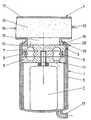
- This shows in a single figure a conveyor unit 1 according to the invention with one of an electric motor 2 driven pump 3 and a filter element 4.
- the electric motor 2 and the pump 3 are in a common pot-shaped housing 5 arranged.
- the pump 3 is designed as a side channel pump and has an impeller 6 driven by the electric motor 2, which between two fixed pump walls 7, 8 rotates.
- the pump walls 7, 8 are of a tubular, the impeller 6 concentric enclosing spacer 9 held in its intended position.
- the spacer 9 has a slightly larger width than the impeller 6 on.
- In the pump wall 7 facing the filter element 4 is a Inlet duct 10 arranged.
- In the other pump wall 8 is an outlet channel 11 incorporated.
- the filter element 4 has a filter housing 12 with a filter insert 13 arranged therein.
- the filter insert 13 can be made of foam, for example.
- the housing 5 of the conveyor unit 1 is facing the filter element 4 Side made in one piece with a clamping element 18.
- the Clamping element 18 has a circumferential edge 19 to engage behind of the filter housing 12 a flanging 20. This will make the filter housing 12 against the pump wall having the inlet duct 10 7 biased and at the same time the individual components of the pump 3 and of the electric motor 2 clamped together.
- the electric motor 2 the pump 3 and the filter element 4 can simply be inserted into the pot-shaped housing 5.
Landscapes
- Engineering & Computer Science (AREA)
- Chemical & Material Sciences (AREA)
- Combustion & Propulsion (AREA)
- Mechanical Engineering (AREA)
- General Engineering & Computer Science (AREA)
- Structures Of Non-Positive Displacement Pumps (AREA)
- Cooling, Air Intake And Gas Exhaust, And Fuel Tank Arrangements In Propulsion Units (AREA)
Description
Claims (5)
- Fördereinheit mit einer eine Pumpenwand (7) aufweisenden Pumpe (3), mit einem an der Pumpenwand (7) im Bereich eines Einlasskanals (10) zu befestigenden Filterelement (4) und mit Spannmitteln zur Vorspannung des Filterelementes (4) gegen die Pumpenwand (7), wobei das Filterelement (4) Ansaugöffnungen (14, 15) aufweist, dadurch gekennzeichnet, dass die Ansaugöffnungen (14, 15) des Filterelementes (4) radial zur Pumpenachse in einem Filtergehäuse (12) angeordnet sind.
- Fördereinheit nach Anspruch 1, dadurch gekennzeichnet, daß sie ein Spannelement (18) zum Vorspannen des Filterelementes (4) aufweist.
- Fördereinheit nach Anspruch 1 oder 2, dadurch gekennzeichnet, daß das Spannelement (18) aus einem Blechstreifen gefertigt und einen Rand (19) des Filterelementes (4) und einen Rand der Fördereinheit (1) hintergreifend gestaltet ist.
- Fördereinheit nach Anspruch 1 oder 2, dadurch gekennzeichnet, daß das Spannelement (18) einteilig mit einem Gehäuse (5) der Fördereinheit (1) oder der Pumpe (3) gefertigt ist und eine an dem Rand (19) des Filterelementes (4) anliegende Umbördelung (20) aufweist.
- Fördereinheit nach zumindest einem der vorhergehenden Ansprüche, dadurch gekennzeichnet, daß die Pumpenwand (7, 8) aus Keramik im Sinterverfahren hergestellt ist.
Applications Claiming Priority (3)
| Application Number | Priority Date | Filing Date | Title |
|---|---|---|---|
| DE19718792A DE19718792A1 (de) | 1997-05-03 | 1997-05-03 | Fördereinheit |
| DE19718792 | 1997-05-03 | ||
| PCT/EP1998/002336 WO1998050695A1 (de) | 1997-05-03 | 1998-04-21 | Fördereinheit |
Publications (2)
| Publication Number | Publication Date |
|---|---|
| EP0980473A1 EP0980473A1 (de) | 2000-02-23 |
| EP0980473B1 true EP0980473B1 (de) | 2003-06-25 |
Family
ID=7828573
Family Applications (1)
| Application Number | Title | Priority Date | Filing Date |
|---|---|---|---|
| EP98924156A Expired - Lifetime EP0980473B1 (de) | 1997-05-03 | 1998-04-21 | Fördereinheit |
Country Status (6)
| Country | Link |
|---|---|
| US (1) | US6423221B1 (de) |
| EP (1) | EP0980473B1 (de) |
| BR (1) | BR9809428A (de) |
| DE (2) | DE19718792A1 (de) |
| ES (1) | ES2202862T3 (de) |
| WO (1) | WO1998050695A1 (de) |
Families Citing this family (3)
| Publication number | Priority date | Publication date | Assignee | Title |
|---|---|---|---|---|
| JP2002161899A (ja) * | 2000-11-27 | 2002-06-07 | Asmo Co Ltd | 流体ポンプ装置 |
| JP2004204731A (ja) * | 2002-12-24 | 2004-07-22 | Denso Corp | 燃料ポンプ |
| JP6380363B2 (ja) * | 2015-12-17 | 2018-08-29 | 株式会社デンソー | 燃料ポンプユニット |
Family Cites Families (25)
| Publication number | Priority date | Publication date | Assignee | Title |
|---|---|---|---|---|
| US2306297A (en) * | 1941-08-14 | 1942-12-22 | Curtis Pump Co | Booster pump screen |
| US2494086A (en) * | 1943-11-29 | 1950-01-10 | Thompson Prod Inc | Pump entry vane construction |
| US2464196A (en) * | 1945-08-10 | 1949-03-08 | Cornelius W Van Ranst | Fuel pump |
| US2576894A (en) * | 1945-12-08 | 1951-11-27 | Ranst Van | Fuel pump |
| US2818027A (en) * | 1956-04-19 | 1957-12-31 | Gen Motors Corp | Fuel pump |
| US2978990A (en) * | 1956-05-03 | 1961-04-11 | George W Lewis | Fluid pumps |
| US2872871A (en) * | 1956-05-10 | 1959-02-10 | Stewart Warner Corp | High capacity fuel pump |
| US3014623A (en) * | 1958-01-29 | 1961-12-26 | Borg Warner | Motor and pump mounting means |
| GB1033241A (en) * | 1964-01-03 | 1966-06-22 | Gen Motors Ltd | Fuel pumps |
| US3398835A (en) * | 1965-09-22 | 1968-08-27 | Walker Mfg Co | Filter |
| US3575296A (en) * | 1968-12-26 | 1971-04-20 | Kenneth E Peterson | Pump system |
| US3530991A (en) * | 1969-05-29 | 1970-09-29 | United Ind Syndicate | Filter and pulsator fuel pumps |
| US3875059A (en) * | 1973-12-10 | 1975-04-01 | Gen Motors Corp | Electric fuel pump strainer stand-off |
| US3950251A (en) * | 1974-03-25 | 1976-04-13 | Rayne International | Filter with quick-connect coupling |
| JPH0633041B2 (ja) * | 1985-01-28 | 1994-05-02 | 日産自動車株式会社 | 自動車の燃料タンク内のフイルタ装置 |
| US4707165A (en) * | 1985-03-04 | 1987-11-17 | Aeroquip Corporation | Gas and fluid separator |
| US4818398A (en) * | 1987-12-21 | 1989-04-04 | Lott W Gerald | Filter system with readily replaceable filter element |
| DE4021500C3 (de) * | 1990-07-05 | 1998-10-22 | Mannesmann Vdo Ag | Förderaggregat, insbesondere zum Fördern von Kraftstoff |
| DE9102825U1 (de) * | 1991-03-09 | 1992-07-09 | Robert Bosch Gmbh, 7000 Stuttgart | Aggregat zum Fördern von Kraftstoff aus einem Vorratstank zur Brennkraftmaschine eines Kraftfahrzeuges |
| DE4119160A1 (de) * | 1991-06-11 | 1992-12-17 | Vdo Schindling | Kraftstoff-foerderpumpe |
| DE4338349C2 (de) * | 1993-11-10 | 2002-10-02 | Bosch Gmbh Robert | Zahnradmaschine |
| US5411376A (en) * | 1993-12-15 | 1995-05-02 | Walbro Corporation | Fuel pump with noise suppression |
| DE4401783A1 (de) * | 1994-01-21 | 1995-07-27 | Cerasiv Gmbh | Förderaggregat mit einer keramischen Innenzahnradpumpe |
| JPH07208291A (ja) * | 1994-01-24 | 1995-08-08 | Mitsubishi Electric Corp | インタンク形ポンプ装置及びその製造方法 |
| DE19513414C2 (de) * | 1995-04-08 | 2003-07-24 | Pierburg Gmbh | Brennstoffördereinheit mit Speichertopf |
-
1997
- 1997-05-03 DE DE19718792A patent/DE19718792A1/de not_active Withdrawn
-
1998
- 1998-04-21 BR BR9809428-9A patent/BR9809428A/pt active Search and Examination
- 1998-04-21 WO PCT/EP1998/002336 patent/WO1998050695A1/de not_active Ceased
- 1998-04-21 EP EP98924156A patent/EP0980473B1/de not_active Expired - Lifetime
- 1998-04-21 ES ES98924156T patent/ES2202862T3/es not_active Expired - Lifetime
- 1998-04-21 US US09/423,256 patent/US6423221B1/en not_active Expired - Fee Related
- 1998-04-21 DE DE59808828T patent/DE59808828D1/de not_active Expired - Fee Related
Also Published As
| Publication number | Publication date |
|---|---|
| WO1998050695A1 (de) | 1998-11-12 |
| DE19718792A1 (de) | 1998-11-05 |
| US6423221B1 (en) | 2002-07-23 |
| ES2202862T3 (es) | 2004-04-01 |
| EP0980473A1 (de) | 2000-02-23 |
| BR9809428A (pt) | 2000-06-13 |
| DE59808828D1 (de) | 2003-07-31 |
Similar Documents
| Publication | Publication Date | Title |
|---|---|---|
| EP1417110B1 (de) | Fördereinheit zur anordnung in einem schwalltopf eines kraftstoffbehälters eines kraftfahrzeuges | |
| DE19753860C1 (de) | Kraftstoff-Förderaggregat mit verbesserter Förderpumpe | |
| DE10224784A1 (de) | G-Rotorpumpe | |
| EP0982491A2 (de) | Fördereinheit | |
| DE4446106C2 (de) | Brennstoffpumpe für Kraftfahrzeuge | |
| DE10341841A1 (de) | Nach dem Gerotorprinzip arbeitende Kraftstoffpumpe | |
| DE102014224657B4 (de) | Klimatisierungsanlage mit Radialgebläse | |
| DE2906224A1 (de) | Kraftstoff-foerderaggregat | |
| EP0358731B1 (de) | Axiallüfter | |
| DE19941786B4 (de) | Förderpumpe | |
| DE10327321A1 (de) | Als G-Rotorpumpe ausgebildete Verdrängerpumpe | |
| EP1703135B1 (de) | Spaltrohr einer Kreiselmotorpumpe | |
| DE102009012946A1 (de) | Ventileinrichtung | |
| DE19718792A1 (de) | Fördereinheit | |
| EP0980477A1 (de) | Fördereinheit | |
| EP1030432B1 (de) | Elektromotor | |
| EP1611339A1 (de) | Kraftstofffilter für ein kraftfahrzeug | |
| DE10341840B4 (de) | Kraftstoff-Fördereinheit | |
| DE10322621B4 (de) | Zur Befestigung in einem Kraftstoffbehälter vorgesehene Fördereinheit | |
| DE102016125392A1 (de) | Scrollkompressor | |
| DE10054590B4 (de) | Kraftstoffpumpe | |
| DE10246725A1 (de) | Kraftstofffördereinheit | |
| EP1704321B1 (de) | Kraftstoff-fördereinheit | |
| DE2223066A1 (de) | Geblaeseeinheit, vorzugsweise fuer oel- oder gasbrenner | |
| WO2009065751A1 (de) | Kraftstoffpumpe |
Legal Events
| Date | Code | Title | Description |
|---|---|---|---|
| PUAI | Public reference made under article 153(3) epc to a published international application that has entered the european phase |
Free format text: ORIGINAL CODE: 0009012 |
|
| 17P | Request for examination filed |
Effective date: 19991027 |
|
| AK | Designated contracting states |
Kind code of ref document: A1 Designated state(s): DE ES FR GB |
|
| 17Q | First examination report despatched |
Effective date: 20010906 |
|
| RAP1 | Party data changed (applicant data changed or rights of an application transferred) |
Owner name: SIEMENS AKTIENGESELLSCHAFT |
|
| GRAH | Despatch of communication of intention to grant a patent |
Free format text: ORIGINAL CODE: EPIDOS IGRA |
|
| GRAH | Despatch of communication of intention to grant a patent |
Free format text: ORIGINAL CODE: EPIDOS IGRA |
|
| GRAA | (expected) grant |
Free format text: ORIGINAL CODE: 0009210 |
|
| AK | Designated contracting states |
Designated state(s): DE ES FR GB |
|
| REG | Reference to a national code |
Ref country code: GB Ref legal event code: FG4D Free format text: NOT ENGLISH |
|
| REF | Corresponds to: |
Ref document number: 59808828 Country of ref document: DE Date of ref document: 20030731 Kind code of ref document: P |
|
| GBT | Gb: translation of ep patent filed (gb section 77(6)(a)/1977) |
Effective date: 20031022 |
|
| REG | Reference to a national code |
Ref country code: ES Ref legal event code: FG2A Ref document number: 2202862 Country of ref document: ES Kind code of ref document: T3 |
|
| PLBE | No opposition filed within time limit |
Free format text: ORIGINAL CODE: 0009261 |
|
| STAA | Information on the status of an ep patent application or granted ep patent |
Free format text: STATUS: NO OPPOSITION FILED WITHIN TIME LIMIT |
|
| ET | Fr: translation filed | ||
| 26N | No opposition filed |
Effective date: 20040326 |
|
| PGFP | Annual fee paid to national office [announced via postgrant information from national office to epo] |
Ref country code: DE Payment date: 20050620 Year of fee payment: 8 |
|
| PGFP | Annual fee paid to national office [announced via postgrant information from national office to epo] |
Ref country code: GB Payment date: 20060411 Year of fee payment: 9 |
|
| PGFP | Annual fee paid to national office [announced via postgrant information from national office to epo] |
Ref country code: FR Payment date: 20060425 Year of fee payment: 9 |
|
| PGFP | Annual fee paid to national office [announced via postgrant information from national office to epo] |
Ref country code: ES Payment date: 20060516 Year of fee payment: 9 |
|
| PG25 | Lapsed in a contracting state [announced via postgrant information from national office to epo] |
Ref country code: DE Free format text: LAPSE BECAUSE OF NON-PAYMENT OF DUE FEES Effective date: 20061101 |
|
| GBPC | Gb: european patent ceased through non-payment of renewal fee |
Effective date: 20070421 |
|
| PG25 | Lapsed in a contracting state [announced via postgrant information from national office to epo] |
Ref country code: GB Free format text: LAPSE BECAUSE OF NON-PAYMENT OF DUE FEES Effective date: 20070421 |
|
| REG | Reference to a national code |
Ref country code: ES Ref legal event code: FD2A Effective date: 20070423 |
|
| PG25 | Lapsed in a contracting state [announced via postgrant information from national office to epo] |
Ref country code: FR Free format text: LAPSE BECAUSE OF NON-PAYMENT OF DUE FEES Effective date: 20070430 |
|
| PG25 | Lapsed in a contracting state [announced via postgrant information from national office to epo] |
Ref country code: ES Free format text: LAPSE BECAUSE OF NON-PAYMENT OF DUE FEES Effective date: 20070423 |