EP0980467B1 - Technique permettant de determiner la valeur energetique d'un carburant fourni a un moteur - Google Patents
Technique permettant de determiner la valeur energetique d'un carburant fourni a un moteur Download PDFInfo
- Publication number
- EP0980467B1 EP0980467B1 EP99908603A EP99908603A EP0980467B1 EP 0980467 B1 EP0980467 B1 EP 0980467B1 EP 99908603 A EP99908603 A EP 99908603A EP 99908603 A EP99908603 A EP 99908603A EP 0980467 B1 EP0980467 B1 EP 0980467B1
- Authority
- EP
- European Patent Office
- Prior art keywords
- fuel
- engine
- value
- energy content
- stored
- Prior art date
- Legal status (The legal status is an assumption and is not a legal conclusion. Google has not performed a legal analysis and makes no representation as to the accuracy of the status listed.)
- Expired - Lifetime
Links
Images


Classifications
-
- F—MECHANICAL ENGINEERING; LIGHTING; HEATING; WEAPONS; BLASTING
- F02—COMBUSTION ENGINES; HOT-GAS OR COMBUSTION-PRODUCT ENGINE PLANTS
- F02D—CONTROLLING COMBUSTION ENGINES
- F02D19/00—Controlling engines characterised by their use of non-liquid fuels, pluralities of fuels, or non-fuel substances added to the combustible mixtures
- F02D19/06—Controlling engines characterised by their use of non-liquid fuels, pluralities of fuels, or non-fuel substances added to the combustible mixtures peculiar to engines working with pluralities of fuels, e.g. alternatively with light and heavy fuel oil, other than engines indifferent to the fuel consumed
- F02D19/08—Controlling engines characterised by their use of non-liquid fuels, pluralities of fuels, or non-fuel substances added to the combustible mixtures peculiar to engines working with pluralities of fuels, e.g. alternatively with light and heavy fuel oil, other than engines indifferent to the fuel consumed simultaneously using pluralities of fuels
- F02D19/10—Controlling engines characterised by their use of non-liquid fuels, pluralities of fuels, or non-fuel substances added to the combustible mixtures peculiar to engines working with pluralities of fuels, e.g. alternatively with light and heavy fuel oil, other than engines indifferent to the fuel consumed simultaneously using pluralities of fuels peculiar to compression-ignition engines in which the main fuel is gaseous
- F02D19/105—Controlling engines characterised by their use of non-liquid fuels, pluralities of fuels, or non-fuel substances added to the combustible mixtures peculiar to engines working with pluralities of fuels, e.g. alternatively with light and heavy fuel oil, other than engines indifferent to the fuel consumed simultaneously using pluralities of fuels peculiar to compression-ignition engines in which the main fuel is gaseous operating in a special mode, e.g. in a liquid fuel only mode for starting
-
- F—MECHANICAL ENGINEERING; LIGHTING; HEATING; WEAPONS; BLASTING
- F02—COMBUSTION ENGINES; HOT-GAS OR COMBUSTION-PRODUCT ENGINE PLANTS
- F02B—INTERNAL-COMBUSTION PISTON ENGINES; COMBUSTION ENGINES IN GENERAL
- F02B7/00—Engines characterised by the fuel-air charge being ignited by compression ignition of an additional fuel
- F02B7/06—Engines characterised by the fuel-air charge being ignited by compression ignition of an additional fuel the fuel in the charge being gaseous
-
- F—MECHANICAL ENGINEERING; LIGHTING; HEATING; WEAPONS; BLASTING
- F02—COMBUSTION ENGINES; HOT-GAS OR COMBUSTION-PRODUCT ENGINE PLANTS
- F02D—CONTROLLING COMBUSTION ENGINES
- F02D19/00—Controlling engines characterised by their use of non-liquid fuels, pluralities of fuels, or non-fuel substances added to the combustible mixtures
- F02D19/02—Controlling engines characterised by their use of non-liquid fuels, pluralities of fuels, or non-fuel substances added to the combustible mixtures peculiar to engines working with gaseous fuels
- F02D19/026—Measuring or estimating parameters related to the fuel supply system
- F02D19/027—Determining the fuel pressure, temperature or volume flow, the fuel tank fill level or a valve position
-
- F—MECHANICAL ENGINEERING; LIGHTING; HEATING; WEAPONS; BLASTING
- F02—COMBUSTION ENGINES; HOT-GAS OR COMBUSTION-PRODUCT ENGINE PLANTS
- F02D—CONTROLLING COMBUSTION ENGINES
- F02D19/00—Controlling engines characterised by their use of non-liquid fuels, pluralities of fuels, or non-fuel substances added to the combustible mixtures
- F02D19/06—Controlling engines characterised by their use of non-liquid fuels, pluralities of fuels, or non-fuel substances added to the combustible mixtures peculiar to engines working with pluralities of fuels, e.g. alternatively with light and heavy fuel oil, other than engines indifferent to the fuel consumed
- F02D19/0602—Control of components of the fuel supply system
- F02D19/0607—Control of components of the fuel supply system to adjust the fuel mass or volume flow
- F02D19/061—Control of components of the fuel supply system to adjust the fuel mass or volume flow by controlling fuel injectors
-
- F—MECHANICAL ENGINEERING; LIGHTING; HEATING; WEAPONS; BLASTING
- F02—COMBUSTION ENGINES; HOT-GAS OR COMBUSTION-PRODUCT ENGINE PLANTS
- F02D—CONTROLLING COMBUSTION ENGINES
- F02D19/00—Controlling engines characterised by their use of non-liquid fuels, pluralities of fuels, or non-fuel substances added to the combustible mixtures
- F02D19/06—Controlling engines characterised by their use of non-liquid fuels, pluralities of fuels, or non-fuel substances added to the combustible mixtures peculiar to engines working with pluralities of fuels, e.g. alternatively with light and heavy fuel oil, other than engines indifferent to the fuel consumed
- F02D19/0663—Details on the fuel supply system, e.g. tanks, valves, pipes, pumps, rails, injectors or mixers
- F02D19/0686—Injectors
- F02D19/0692—Arrangement of multiple injectors per combustion chamber
-
- Y—GENERAL TAGGING OF NEW TECHNOLOGICAL DEVELOPMENTS; GENERAL TAGGING OF CROSS-SECTIONAL TECHNOLOGIES SPANNING OVER SEVERAL SECTIONS OF THE IPC; TECHNICAL SUBJECTS COVERED BY FORMER USPC CROSS-REFERENCE ART COLLECTIONS [XRACs] AND DIGESTS
- Y02—TECHNOLOGIES OR APPLICATIONS FOR MITIGATION OR ADAPTATION AGAINST CLIMATE CHANGE
- Y02T—CLIMATE CHANGE MITIGATION TECHNOLOGIES RELATED TO TRANSPORTATION
- Y02T10/00—Road transport of goods or passengers
- Y02T10/10—Internal combustion engine [ICE] based vehicles
- Y02T10/30—Use of alternative fuels, e.g. biofuels
Definitions
- This invention relates generally to internal combustion engine systems capable of controllably delivering two fuels to the engine for simultaneous combustion, and more particularly, to a method for determining the energy content of one of the fuels delivered to an internal combustion engine in order to account for variations which can occur in the energy content of such fuel.
- a spark-ignited engine system can include a first valve for controllably delivering a known mass flow of a first fuel to an engine cylinder and a second valve for controllably delivering a known mass flow of a second fuel to an engine cylinder, the two fuels being simultaneously ignited by a spark plug disposed within the cylinder.
- An engine can also be configured as a dual fuel engine. Although the description contained herein is directed mainly to dual fuel engines it is recognized that the described methods are applicable to other types of engines which burn a blend of two fuels.
- a dual fuel engine can typically operate in two modes.
- a liquid fuel such as diesel fuel
- a gaseous fuel such as natural gas
- a small amount or pilot amount of diesel fuel is injected into the cylinder or the precombustion chamber in order to ignite the mixture of air and gaseous fuel.
- a liquid fuel such as diesel fuel has a substantially constant energy content.
- the energy content of a gaseous fuel such as natural gas can vary. It is desirable that a dual fuel engine fuel control system which utilizes gaseous fuel energy content to determine the amount of gaseous fuel to deliver to the engine should be able to account for variations in the gaseous fuel energy content.
- the energy content of a first fuel may be substantially constant, or at least always known based upon measurement by a gas chromatograph for example, and the energy content of a second fuel may be variable.
- the present invention is directed to overcoming one or more of the problems as set forth above.
- a method for adjusting a fuel control system of an engine capable of operating in both a first mode during which only a first fuel is delivered to the engine and a second mode during which both the first fuel and a second fuel are delivered to the engine is provided.
- the fuel control system utilizes a stored second fuel energy content value (EF 2 ) to determine the necessary duration of a second fuel valve control signal during engine operation in the second mode.
- the method includes operating the engine in the first mode during which a governor output value (X M1 ) indicative of a total fuel energy rate being delivered to the engine is established and stored in memory.
- the engine is then operated in the second mode during which a governor output value (X M2 ) indicative of a total fuel energy rate being delivered to the engine is established.
- the governor output value (X M2 ) is compared with the stored governor output value (X M1 ) and the stored second fuel energy content value (E F2 ) is adjusted based upon the comparison.
- a method of determining the energy content of a second fuel delivered to an engine system capable of operating in both a first mode during which only a first fuel is delivered to the engine and a second mode during which both the first fuel and the second fuel are delivered to the engine is provided.
- the engine system utilizes a stored second fuel energy content value (E F2 ) to determine the necessary duration of a second fuel valve control signal during engine operation in the second mode.
- the method includes operating the engine in the first mode during which a governor output value (X M1 ) indicative of a total fuel energy rate being delivered to the engine is established and stored in memory.
- An updated second fuel energy content value (E F2 ') can then be calculated.
- a method for determining the energy content of a second fuel delivered to an engine wherein the energy content of a first fuel delivered to the engine is known is provided.
- a fuel control system of the engine utilizes a stored second fuel energy content value (E F2 ) to determine the necessary duration of a second fuel valve control signal when both fuels are being delivered to the engine.
- the method includes providing a fuel system governor which continuously outputs a value (X) indicative of a total fuel energy rate being delivered to the engine.
- the first fuel value (Y M1 ) and the second fuel value (Z M1 ) are stored.
- An updated energy content value (E F2 ') can then be calculated.
- the engine is a dual fuel engine and the first fuel is a liquid fuel, the second fuel is a gaseous fuel, the first mode is a liquid fuel mode, the second mode is a dual fuel mode, and the second fuel valve control signal is a gaseous fuel admission valve control signal.
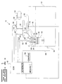
- FIG. 1 depicts a dual fuel engine system including an engine 12 with a representative cylinder 14 shown. Although only one cylinder 14 is shown, it is recognized that number of cylinders of engine 12 could vary and that engine 12 could be of the in-line type, v-type, or even a rotary type engine.
- Piston 16 is positioned for displacement within cylinder 14, which cylinder 14 includes an intake port 18 and an exhaust port 20 including respective valves 22 and 24.
- Intake port 18 receives air from an air intake manifold 26 to which intake air travels after passing through, for example, an air filter (not shown) and turbocharger (not shown).
- Engine 12 includes a fuel injector 28, such as an electronic unit injector, positioned for injecting liquid fuel, such as diesel fuel, into cylinder 14.
- the liquid fuel may be provided to fuel injector 28 by means commonly known in the art.
- a gaseous fuel admission valve 30 is positioned between a gaseous fuel manifold 32 at an upstream side and intake port 18 at a downstream side, a nozzle portion of valve 30 extending into intake port 18 for delivering gaseous fuel thereto.
- Gaseous fuel admission valve 30 may, for example, be of the type shown and described in U.S. Patent No. 5,398,724 available from Woodward Governor Company.
- Gaseous fuel manifold 32 is connected to a source of gaseous fuel 34 by fuel path 36, a solenoid operated gaseous fuel shut off valve 38 being positioned along fuel path 36.
- a solenoid operated gaseous fuel shut off valve 38 being positioned along fuel path 36.
- such a system might typically include a balance regulator positioned between gaseous fuel source 34 and gaseous fuel manifold 32 for regulating the gaseous fuel pressure at the upstream side of gaseous fuel admission valve 30.
- An electronic control module (ECM) 40 is connected to a gaseous fuel pressure sensor 42 via conductive path 44 and to an intake air pressure sensor 46 via conductive path 48 for receiving pressure indicative signals from each of such sensors.
- pressure sensors are well known in the art and therefore a detailed description of the sensors is not included herein.
- a temperature sensor 43 is also provided in gaseous fuel manifold 32 to provide temperature indicative signals to ECM 40 via conductive path 45.
- ECM 40 is connected for controlling gaseous fuel admission valve 30 by conductive path 50 and is also connected for controlling fuel injector 28 by conductive path 52.
- driver circuitry could be formed separate from, but connected to, ECM 40.
- An engine speed sensor 54 associated with a camshaft of engine 12 is also connected to ECM 40 via conductive path 56 for delivering engine speed indicative signals thereto.
- ECM 40 typically includes processing means, such as a microcontroller or microprocessor, associated electronic circuitry such as input/output circuitry, as well as associated memory.
- Dual fuel engine system 10 can operate in both a liquid fuel mode and a dual fuel mode.
- the liquid fuel mode the liquid fuel is injected into engine cylinder 14 as the sole source of fuel energy during combustion.
- the gaseous fuel is mixed with air in intake port 18 of cylinder 14 and a small amount or pilot amount of liquid fuel is injected into cylinder 14 in order to ignite the mixture of air and gaseous fuel.
- the fuel control system of engine 12 operates by establishing a governor output value (X) indicative of a total fuel energy rate desired to be delivered to the engine to maintain a desired engine speed.
- the desired engine speed may be a predetermined, stored engine speed or it may be indicated by a throttle setting for example.
- a first value (Y) indicative of a liquid pilot fuel energy rate desired to be delivered to the engine and a second value (Z) indicative of a gaseous fuel energy rate desired to be delivered to the engine are each determined such that the sum of the desired liquid pilot fuel energy rate and the desired gaseous fuel energy rate is substantially equal to the desired total fuel energy.
- a fuel injector control signal duration and a gaseous fuel admission valve control signal duration are both determined such that the liquid fuel delivered to the engine provides the desired liquid pilot fuel energy rate and the gaseous fuel delivered to the engine provides the desired gaseous fuel energy rate.
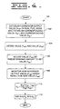
- a flowchart 60 of operating steps in accordance with one aspect of the present invention is shown.
- Engine 12 is operated in a liquid fuel mode and a governor output value (X M1 ) indicative of the total fuel energy rate being delivered to the engine is established at step 62.
- the governor output value (X M1 ) is stored for later retrieval at step 64.
- a governor output value (X M2 ) is established as indicated at step 66.
- the difference (D) between value (X M1 ) and value (X M2 ) is determined at step 68 and the difference (D) is compared with a threshold difference at step 70. If the absolute value of difference (D) exceeds the threshold difference then the stored energy content value (E G ) is adjusted at step 72.
- the stored energy content value (E G ) is used to determine the necessary duration of the gaseous fuel admission valve control signal. Further, the fuel control system is configured to provide a substantially constant total fuel energy rate to the engine regardless of the engine operating mode as long as the engine load remains substantially constant. Accordingly, when the difference between governor output value (X M1 ) in the liquid fuel mode and the governor output value (X M2 ) in the dual fuel mode is significant, such is indicative of the stored gaseous fuel energy content value (E G ) being incorrect. The stored gaseous fuel energy content value (E G ) is therefore adjusted at step 72 when the absolute value of difference (D) exceeds the threshold difference, which threshold difference may be established by engine testing.
- monitoring of the engine load should preferably be performed before making an adjustment to the stored gaseous fuel energy content value (E G ).
- the engine load may be monitored and stored in memory as (L M1 ).
- the engine load (L M2 ) may again be monitored and compared with the stored engine load (L M1 ). If the difference between the two load values (L M1 ) and (L M2 ) is less than a predetermined amount, then the energy content adjustment can be made if necessary.
- the adjustment of the stored gaseous fuel energy content value (E G ) may be made in a variety of ways. As a general matter, if the difference (D) determined at step 68 is negative such is indicative of the stored gaseous fuel energy content value (E G ) being too high. If the difference (D) is positive such is indicative of the stored gaseous fuel energy content value (E G ) being too low. Accordingly, the stored gaseous fuel energy content value (E G ) is decreased at step 72 if (X M2 ) is greater than (X M1 ) and the stored gaseous fuel energy content value (E G ) is increased at step 72 if (X M2 ) is less than (X M1 ).
- the stored gaseous fuel energy content value (E G ) can be increased/decreased by a predetermined amount, such as by a predetermined percentage, or the gaseous fuel energy content can be increased/decreased by an amount which is a function of the difference (D). Steps 66, 68, 70 and 72 could be repeated until the absolute value of the difference (D) falls below the threshold difference.
- the actual energy content of the gaseous fuel is calculated directly performing the steps set out in flowchart 80 of Fig. 3.
- Steps 82 and 84 of Fig. 3 correspond to steps 62 and 64 of Fig. 2.
- a governor output value (X M2 ) is established in the dual fuel mode.
- An updated gaseous fuel energy content value (E G ') can then be determined in accordance with the equation set forth in step 88 and at step 90 the stored gaseous fuel energy content value (E G ) is then replaced with the updated gaseous fuel energy content value (E G ' ) .
- the method of Fig. 3 again assumes a constant engine load and therefore it is desirable to monitor the engine load as described with respect to the method of Fig. 2.
- step 90 it is recognized that if the updated gaseous fuel energy content value (E G ') is significantly different than the stored gaseous fuel energy content value (E G ) it may be desirable to adjust the stored value (E G ) in a series of incremental steps.
- a governor output value (X M1 ) indicative of the total fuel energy rate is established at step 102.
- the value (Y M1 ) and the value (Z M1 ) are stored in memory at step 104 for later retrieval.
- the liquid pilot fuel value (Y M1 ) is increased/decreased by a predetermined amount to (Y M2 ).
- step 112 it is again recognized that if the updated gaseous fuel energy content value (E G ') is significantly different than the stored gaseous fuel energy content value (E G ) it may be desirable to adjust the stored value (E G ) in a series of incremental steps.
- the present invention enables the gaseous fuel energy content of a gaseous fuel to be determined during engine operation such that proper gaseous fuel delivery to the engine can be maintained during dual fuel engine operation.
- energy content determination is necessary as the energy content of natural gas can vary significantly.
- the energy content adjustment can be performed as necessary or desired in a given application. For example, the energy content adjustment could be performed on a predetermined periodic basis or the energy content adjustment could be performed whenever the governor output value (X) in the dual fuel mode changes a significant amount.
- a spark-ignited engine may include two gaseous fuel admission valves for each cylinder for controllably delivering two different gaseous fuels to each cylinder.
- Such an engine would be capable of delivering a first fuel having a known energy content and a second fuel having a variable energy content.
- a stored second fuel energy content value (E F2 ) might be utilized for determining the necessary duration of a second fuel valve control signal.
- the value (Y) would correspond to the first fuel and the value (Z) would correspond to the second fuel.
- An updated energy content value (E F2 ' ) could be calculated using the equations of Figs. 3 and 4 where term (E F2 ) is substituted for term (E G ) in the equations and term (E F2 ' ) is substituted for term (E G ') in the equations.
- E G stored energy content value
- E F2 stored energy content value
Landscapes
- Engineering & Computer Science (AREA)
- Chemical & Material Sciences (AREA)
- Combustion & Propulsion (AREA)
- Mechanical Engineering (AREA)
- General Engineering & Computer Science (AREA)
- Oil, Petroleum & Natural Gas (AREA)
- Electrical Control Of Air Or Fuel Supplied To Internal-Combustion Engine (AREA)
- Output Control And Ontrol Of Special Type Engine (AREA)
- Air-Conditioning For Vehicles (AREA)
- Combined Controls Of Internal Combustion Engines (AREA)
Claims (16)
- Procédé de réglage d'un système de contrôle de carburant (10) d'un moteur (12) apte à fonctionner dans un premier mode dans lequel seul un premier carburant est fourni au moteur et dans un second mode dans lequel le premier carburant et un second carburant sont fournis au moteur, le système de contrôle de carburant utilisant une valeur énergétique mémorisée du second carburant (EF2) pour déterminer la durée nécessaire d'un signal de commande de soupape de second carburant pendant le fonctionnementdu moteur dans lesecond mode, la valeur énergétique du premier carburant étant connue, le procédé comprenant les étapes suivantes :a) actionner le moteur dans le premier mode dans lequel une valeur de sortie de régulateur (XM1) indicative d'un taux d'énergie de carburant total fourni au moteur est établie et stockée en mémoire ;b) actionner le moteur dans le second mode dans lequel une valeur de sortie de régulateur (XM2) indicative d'un taux d'énergie total de carburant fourni au moteur est établie ;c) comparer la valeur de sortie de régulateur (XM2) à la valeur de sortie de régulateur mémorisée (XM1) ; etd) régler la valeur énergétique mémorisée du second carburant (EF2) sur la base de la comparaison faite à l'étape c).
- Procédé selon la revendication 1, dans lequel :l'étape c) comprend la détermination d'une différence (D) entre la valeur de sortie de régulateur mémorisée (XM1) et la valeur de sortie de régulateur (XM2) ; etl'étape d) est réalisée seulement quand la valeur absolue de la différence (D) dépasse une différence de seuil.
- Procédé selon la revendication 2, dans lesquelles les étapes b), c) et d) sont répétées jusqu'à ce que la valeur absolue de la différence (D) ne dépasse plus la différence de seuil.
- Procédé selon la revendication 2, dans lequel
l'étape d) comprend le réglage de la valeur énergétique mémorisée du second carburant (EF2) d'une quantité qui est fonction de la différence (D). - Procédé selon la revendication 1, dans lequel
l'étape d) comprend le réglage de la valeur énergétique mémorisée du second carburant (EF2) d'une quantité prédéterminée. - Procédé selon la revendication 1, dans lequel
l'étape d) comprend l'augmentation de la valeur énergétique mémorisée du second carburant (EF2) si la valeur de sortie de régulateur (XM2) est au moins d'une quantité prédéterminée inférieure à la valeur de sortie de régulateur mémorisée (XM1 ). - Procédé selon la revendication 6, dans lequel
l'étape d) comprend la diminution de la valeur énergétique mémorisée du second carburant (EF2) si la valeur de sortie de régulateur (XM2) est d'au moins une quantité prédéterminée supérieure à la valeur de sortie de régulateur mémorisée (XM1) . - Procédé selon la revendication 1, comprenant les étapes suivantes :e) détecter la charge (LM1) du moteur à l'instant où la valeur de sortie de régulateur mémorisée (XM1) est établie à l'étape a) ;f) mémoriser la charge de moteur détectée (LM1) ;g) détecter la charge de moteur (LM2) à l'instant où l'étape b) est réalisée ;h) comparer la charge de moteur détectée (LM2) à la charge de moteur mémorisée (LM1) et ;i) réaliser l'étape d) seulement si la charge de moteur (LM2) est sensiblement identique à la charge de moteur mémorisée (LM1)
- Procédé selon la revendication 1, dans lequel le moteur (12) est un moteur à deux carburants et dans lequel le premier carburant est un carburant liquide, le second carburant est un carburant gazeux, le premier mode est un mode de carburant liquide, le second mode est un mode de carburant double et le signal de commande de soupape de second carburant est un signal de commande de soupape d'admission de carburant gazeux.
- Procédé de détermination de la valeur énergétique d'un second carburant fourni à un système de moteur (10) apte à fonctionner dans un premier mode dans lequel seul un premier carburant est fourni au moteur et un second mode dans lequel le premier carburant et le second carburant sont fournis au moteur, le système de moteur utilisant une valeur énergétique mémorisée de second carburant (EF2) pour déterminer la durée nécessaire d'un signal de commande de soupape de second carburant pendant le fonctionnement du moteur dans le second mode, la valeur énergétique du premier carburant étant connue, le procédé comprenant les étapes suivantes :a) actionner le moteur dans le premier mode pendant lequel une valeur de sortie de régulateur XM1 indicative du taux d'énergie total de carburant fourni au moteur dans lequel une première valeur de carburant est établie et stockée en mémoire ;b) actionner le moteur dans le second mode dans lequel une valeur de sortie de régulateur XM2 indicative du taux d'énergie total de carburant fourni au moteur dans lequel une première valeur de carburant YM2 est établie et une seconde valeur de carburant ZM2 est établie de sorte que:c) calculer une valeur du contenu en énergie mise à jour de second carburant EF2' en accord avec l'équation suivante :
- Procédé selon la revendication 10, comprenant l'étape suivante :d) remplacer la valeur énergétique mémorisée du second carburant EF2 par la valeur énergétique mise à jour du second carburant EF2'.
- Procédé selon la revendication 10, dans lequel le moteur (12) est un moteur à deux carburants et dans lequel le premier carburant est un carburant liquide, le second carburant est un carburant gazeux, le premier mode est un mode à carburant liquide, le second mode est un mode à carburant gazeux et le signal de commande de soupape de second carburant est un signal de commande de soupape d'admission de carburant gazeux.
- Procédé selon la revendication 10, dans lequel les étapes a) et b) sont réalisées sensiblement à la même charge du moteur.
- Procédé pour déterminer la valeur énergétique d'un second carburant fourni à un moteur (12) dans lequel la valeur énergétique d'un premier carburant fourni au moteur est connue, un système de commande de carburant (10) du moteur utilisant une valeur énergétique mémorisée de second carburant EF2 pour déterminer la durée nécessaire d'un signal de commande de soupape de second carburant quand les deux carburants sont fournis au moteur, le procédé comprenant les étapes suivantes :a) prévoir un régulateur de système de carburant qui fournit en continu une valeur (X) indicative d'un taux d'énergie de carburant total fourni au moteur ;b) établir une première valeur de sortie de régulateur XM1 quand le premier carburant et le second carburant sont fournis au moteur et établir une première valeur de carburant YM1 et une seconde valeur de carburant ZM1 telles que :c) mémoriser la première valeur de carburant YM1 et mémoriser la seconde valeur de carburant ZM1 ;d) modifier la première valeur de carburant YM1 à une valeur YM2 ;e) établir une valeur de sortie de régulateur XM2 et une seconde valeur de carburant ZM2 telles que :f) calculer une valeur énergétique mise à jour (EF2') en accord avec l'équation suivante :
- Procédé selon la revendication 14, comprenant l'étap suivante :g) remplacer la valeur énergétique mémorisée (EF2) par la valeur énergétique mise à jour EF2'.
- Procédé selon la revendication 14, dans lequel le moteur (12) est un moteur à deux carburants et dans lequel le premier carburant est un carburant liquide, le second carburant est un carburant gazeux, le premier mode est un mode de carburant liquide, le second mode est un mode de carburant double et le signal de commande de soupape de second carburant est un signal de commande de soupape d'admission de carburant gazeux.
Applications Claiming Priority (3)
| Application Number | Priority Date | Filing Date | Title |
|---|---|---|---|
| US36110 | 1998-03-06 | ||
| US09/036,110 US5975050A (en) | 1998-03-06 | 1998-03-06 | Method for determining the energy content of a fuel delivered to an engine |
| PCT/US1999/004491 WO1999045252A1 (fr) | 1998-03-06 | 1999-03-01 | Technique permettant de determiner la valeur energetique d'un carburant fourni a un moteur |
Publications (2)
| Publication Number | Publication Date |
|---|---|
| EP0980467A1 EP0980467A1 (fr) | 2000-02-23 |
| EP0980467B1 true EP0980467B1 (fr) | 2003-06-04 |
Family
ID=21886671
Family Applications (1)
| Application Number | Title | Priority Date | Filing Date |
|---|---|---|---|
| EP99908603A Expired - Lifetime EP0980467B1 (fr) | 1998-03-06 | 1999-03-01 | Technique permettant de determiner la valeur energetique d'un carburant fourni a un moteur |
Country Status (5)
| Country | Link |
|---|---|
| US (1) | US5975050A (fr) |
| EP (1) | EP0980467B1 (fr) |
| AT (1) | ATE242424T1 (fr) |
| DE (1) | DE69908512T2 (fr) |
| WO (1) | WO1999045252A1 (fr) |
Families Citing this family (12)
| Publication number | Priority date | Publication date | Assignee | Title |
|---|---|---|---|---|
| FR2817913B1 (fr) | 2000-12-11 | 2003-04-11 | Inst Francais Du Petrole | Methode de gestion d'un moteur a combustion interne fonctionnant en mono ou en bicarburation avec injection directe d'essence et moteur a combustion interne fonctionnant selon une telle methode |
| US6561139B2 (en) | 2001-10-04 | 2003-05-13 | Evan Guy Enterprises, Inc. | Method and apparatus for reducing emissions of internal combustion engines |
| US6863034B2 (en) | 2003-01-17 | 2005-03-08 | Robert D. Kern | Method of controlling a bi-fuel generator set |
| FR2915524B1 (fr) | 2007-04-27 | 2009-07-03 | Inst Francais Du Petrole | Procede pour controler le fonctionnement d'un moteur pouvant utiliser un mode de combustion en monocarburation ou en multicarburation |
| GB0901903D0 (en) * | 2009-02-05 | 2009-03-11 | T Baden Hardstaff Ltd | A fuel injection system |
| BR112014019621A8 (pt) * | 2012-02-09 | 2017-07-11 | Toyota Motor Co Ltd | Sistema de controle para motor de combustão interna de vários combustíveis |
| US9488114B2 (en) * | 2012-11-15 | 2016-11-08 | Caterpillar Inc. | Control strategy for dual gaseous and liquid fuel internal combustion engine |
| EP2915987B1 (fr) * | 2014-03-07 | 2016-12-21 | Caterpillar Motoren GmbH & Co. KG | Évaluation du fonctionnement de la soupape d'admission pour un carburant gazeux |
| WO2016073588A1 (fr) | 2014-11-04 | 2016-05-12 | Cummins Inc. | Systèmes, procédés et appareil pour le fonctionnement de moteurs à deux combustibles |
| US9702328B2 (en) | 2015-05-01 | 2017-07-11 | Caterpillar Inc. | Fuel combustion system having component with knurled conduction surface and method of making same |
| US9739192B2 (en) | 2015-05-04 | 2017-08-22 | Caterpillar Inc. | Fuel combustion system, nozzle for prechamber assembly with curved orifices, and method of making same |
| US9617908B2 (en) | 2015-05-11 | 2017-04-11 | Caterpillar Inc. | Fuel combustion system, nozzle for prechamber assembly having coolant passage, and method of making same |
Family Cites Families (15)
| Publication number | Priority date | Publication date | Assignee | Title |
|---|---|---|---|---|
| US2555818A (en) * | 1946-07-24 | 1951-06-05 | Baldwin Lima Hamilton Corp | Dual fuel engine |
| NZ205140A (en) * | 1983-08-04 | 1987-02-20 | H M Reid | Electronically controlled dual fuel system for diesel engines |
| US4597364A (en) * | 1984-04-30 | 1986-07-01 | Emco Wheaton International Limited | Fuel control system for gaseous fueled engines |
| GB8425577D0 (en) * | 1984-10-10 | 1984-11-14 | Flintheath Ltd | Fuel control system |
| JPH0750099B2 (ja) * | 1987-09-29 | 1995-05-31 | 三菱電機株式会社 | 内燃機関の燃料性状検出装置 |
| US4955326A (en) * | 1989-04-12 | 1990-09-11 | Cooper Industries, Inc. | Low emission dual fuel engine and method of operating same |
| US5140959A (en) * | 1991-01-28 | 1992-08-25 | Durbin Enoch J | Method and apparatus for operation of a dual fuel compression ignition combustion engine |
| US5136986A (en) * | 1991-04-26 | 1992-08-11 | Energy Conversions, Inc. | Dual fuel injection structure |
| US5150685A (en) * | 1991-09-11 | 1992-09-29 | Porter Fred C | Apparatus and method for converting conventionally fueled engines to operate on an alternative fuel |
| US5224457A (en) * | 1992-02-28 | 1993-07-06 | Deere & Company | Dual fuel electronic control system |
| US5226396A (en) * | 1992-09-21 | 1993-07-13 | Caterpillar Inc. | Measuring-signaling apparatus for a multi-fuel system of an engine |
| US5370097A (en) * | 1993-03-22 | 1994-12-06 | Davis Family Trust | Combined diesel and natural gas engine fuel control system and method of using such |
| US5398724A (en) * | 1993-06-28 | 1995-03-21 | Woodward Governor Company | High speed electrically actuated gaseous fuel admission valve |
| US5450829A (en) * | 1994-05-03 | 1995-09-19 | Servojet Products International | Electronically controlled pilot fuel injection of compression ignition engines |
| US5526786A (en) * | 1995-01-23 | 1996-06-18 | Servojet Products International | Dual fuel engine having governor controlled pilot fuel injection system |
-
1998
- 1998-03-06 US US09/036,110 patent/US5975050A/en not_active Expired - Fee Related
-
1999
- 1999-03-01 DE DE69908512T patent/DE69908512T2/de not_active Expired - Fee Related
- 1999-03-01 AT AT99908603T patent/ATE242424T1/de not_active IP Right Cessation
- 1999-03-01 WO PCT/US1999/004491 patent/WO1999045252A1/fr active IP Right Grant
- 1999-03-01 EP EP99908603A patent/EP0980467B1/fr not_active Expired - Lifetime
Also Published As
| Publication number | Publication date |
|---|---|
| WO1999045252A1 (fr) | 1999-09-10 |
| US5975050A (en) | 1999-11-02 |
| ATE242424T1 (de) | 2003-06-15 |
| DE69908512D1 (de) | 2003-07-10 |
| DE69908512T2 (de) | 2004-04-22 |
| EP0980467A1 (fr) | 2000-02-23 |
Similar Documents
| Publication | Publication Date | Title |
|---|---|---|
| EP0980471B1 (fr) | Technique relative a une transition maitrisee entre les modes de fonctionnement d'un moteur hybride | |
| EP0980468B1 (fr) | Technique permettant de maintenir sensiblement constant un taux d'energie de carburant total dans un moteur hybride | |
| EP0986701B1 (fr) | Procede de determination de la teneur en energie d'un carburant introduit dans un moteur sur la base du niveau d'oxygene du gaz d'echappement | |
| EP0980469B1 (fr) | Procede d'equilibrage du rapport air/carburant de chaque cylindre d'un moteur | |
| US6289871B1 (en) | Method for achieving minimum liquid pilot fuel delivery to each cylinder of a dual fuel engine while operating in a dual fuel mode | |
| JP2895620B2 (ja) | 内燃機関の空気/焼料混合比を制御する装置および方法 | |
| EP0981685B1 (fr) | Procede de reaction a la detection d'un etat ouvert errone de soupape d'admission de carburant gazeux dans un moteur | |
| US7044103B2 (en) | Fuel quantity modulation in pilot ignited engines | |
| US5983714A (en) | System for detecting failure of fuel pressure sensor | |
| EP0980467B1 (fr) | Technique permettant de determiner la valeur energetique d'un carburant fourni a un moteur | |
| AU748079B2 (en) | A control method for spark-ignition engines | |
| US6805091B2 (en) | Method for determining the fuel content of the regeneration gas in an internal combustion engine comprising direct fuel-injection with shift operation | |
| WO1999046495A1 (fr) | Technique visant a fournir au moins une certaine quantite pilote de carburant liquide a un moteur hybride | |
| US10927776B2 (en) | Transient controller and method for dual fuel engine | |
| JPH0771296A (ja) | ガスエンジンの燃料供給制御装置 | |
| JPH0771321A (ja) | ガスエンジンの燃料供給制御装置 | |
| JPH0665851B2 (ja) | ロ−タリピストンエンジンの掃気装置 | |
| TH24262EX (th) | ชุดควบคุมเครื่องยนต์ |
Legal Events
| Date | Code | Title | Description |
|---|---|---|---|
| PUAI | Public reference made under article 153(3) epc to a published international application that has entered the european phase |
Free format text: ORIGINAL CODE: 0009012 |
|
| 17P | Request for examination filed |
Effective date: 19991110 |
|
| AK | Designated contracting states |
Kind code of ref document: A1 Designated state(s): AT DE FI GB |
|
| RIN1 | Information on inventor provided before grant (corrected) |
Inventor name: WILLI, MARTIN, L. Inventor name: OHLSON, ERIC, W. Inventor name: BROWN, SCOTT, C. C/O CATERPILLAR INC. |
|
| 17Q | First examination report despatched |
Effective date: 20020328 |
|
| GRAH | Despatch of communication of intention to grant a patent |
Free format text: ORIGINAL CODE: EPIDOS IGRA |
|
| GRAH | Despatch of communication of intention to grant a patent |
Free format text: ORIGINAL CODE: EPIDOS IGRA |
|
| GRAA | (expected) grant |
Free format text: ORIGINAL CODE: 0009210 |
|
| AK | Designated contracting states |
Designated state(s): AT DE FI GB |
|
| PG25 | Lapsed in a contracting state [announced via postgrant information from national office to epo] |
Ref country code: FI Free format text: LAPSE BECAUSE OF FAILURE TO SUBMIT A TRANSLATION OF THE DESCRIPTION OR TO PAY THE FEE WITHIN THE PRESCRIBED TIME-LIMIT Effective date: 20030604 Ref country code: AT Free format text: LAPSE BECAUSE OF FAILURE TO SUBMIT A TRANSLATION OF THE DESCRIPTION OR TO PAY THE FEE WITHIN THE PRESCRIBED TIME-LIMIT Effective date: 20030604 |
|
| REG | Reference to a national code |
Ref country code: GB Ref legal event code: FG4D |
|
| REF | Corresponds to: |
Ref document number: 69908512 Country of ref document: DE Date of ref document: 20030710 Kind code of ref document: P |
|
| PG25 | Lapsed in a contracting state [announced via postgrant information from national office to epo] |
Ref country code: GB Free format text: LAPSE BECAUSE OF NON-PAYMENT OF DUE FEES Effective date: 20040301 |
|
| PLBE | No opposition filed within time limit |
Free format text: ORIGINAL CODE: 0009261 |
|
| STAA | Information on the status of an ep patent application or granted ep patent |
Free format text: STATUS: NO OPPOSITION FILED WITHIN TIME LIMIT |
|
| 26N | No opposition filed |
Effective date: 20040305 |
|
| GBPC | Gb: european patent ceased through non-payment of renewal fee | ||
| PGFP | Annual fee paid to national office [announced via postgrant information from national office to epo] |
Ref country code: DE Payment date: 20060330 Year of fee payment: 8 |
|
| PG25 | Lapsed in a contracting state [announced via postgrant information from national office to epo] |
Ref country code: DE Free format text: LAPSE BECAUSE OF NON-PAYMENT OF DUE FEES Effective date: 20071002 |