EP0979917A2 - Hinge - Google Patents
Hinge Download PDFInfo
- Publication number
- EP0979917A2 EP0979917A2 EP99114727A EP99114727A EP0979917A2 EP 0979917 A2 EP0979917 A2 EP 0979917A2 EP 99114727 A EP99114727 A EP 99114727A EP 99114727 A EP99114727 A EP 99114727A EP 0979917 A2 EP0979917 A2 EP 0979917A2
- Authority
- EP
- European Patent Office
- Prior art keywords
- hinge
- intermediate piece
- hinge arm
- hinge according
- arm
- Prior art date
- Legal status (The legal status is an assumption and is not a legal conclusion. Google has not performed a legal analysis and makes no representation as to the accuracy of the status listed.)
- Withdrawn
Links
Images


Classifications
-
- E—FIXED CONSTRUCTIONS
- E05—LOCKS; KEYS; WINDOW OR DOOR FITTINGS; SAFES
- E05D—HINGES OR SUSPENSION DEVICES FOR DOORS, WINDOWS OR WINGS
- E05D7/00—Hinges or pivots of special construction
- E05D7/04—Hinges adjustable relative to the wing or the frame
- E05D7/0407—Hinges adjustable relative to the wing or the frame the hinges having two or more pins and being specially adapted for cabinets or furniture
-
- E—FIXED CONSTRUCTIONS
- E05—LOCKS; KEYS; WINDOW OR DOOR FITTINGS; SAFES
- E05D—HINGES OR SUSPENSION DEVICES FOR DOORS, WINDOWS OR WINGS
- E05D7/00—Hinges or pivots of special construction
- E05D7/04—Hinges adjustable relative to the wing or the frame
- E05D2007/0461—Hinges adjustable relative to the wing or the frame in angular arrangement to the wing or the frame
-
- E—FIXED CONSTRUCTIONS
- E05—LOCKS; KEYS; WINDOW OR DOOR FITTINGS; SAFES
- E05D—HINGES OR SUSPENSION DEVICES FOR DOORS, WINDOWS OR WINGS
- E05D7/00—Hinges or pivots of special construction
- E05D7/04—Hinges adjustable relative to the wing or the frame
- E05D7/0415—Hinges adjustable relative to the wing or the frame with adjusting drive means
- E05D7/0423—Screw-and-nut mechanisms
-
- E—FIXED CONSTRUCTIONS
- E05—LOCKS; KEYS; WINDOW OR DOOR FITTINGS; SAFES
- E05Y—INDEXING SCHEME RELATING TO HINGES OR OTHER SUSPENSION DEVICES FOR DOORS, WINDOWS OR WINGS AND DEVICES FOR MOVING WINGS INTO OPEN OR CLOSED POSITION, CHECKS FOR WINGS AND WING FITTINGS NOT OTHERWISE PROVIDED FOR, CONCERNED WITH THE FUNCTIONING OF THE WING
- E05Y2900/00—Application of doors, windows, wings or fittings thereof
- E05Y2900/20—Application of doors, windows, wings or fittings thereof for furnitures, e.g. cabinets
Definitions
- the invention relates to a hinge with a preferably by means of a Intermediate piece hinge arm that can be anchored to a base plate without tools Articulated lever or the like with a door-side stop part, for example a hinge cup is connected, wherein adjustment devices are provided, by means of which the position of the Hinge arm relative to the intermediate piece in the direction of the depth of the furniture and / or is adjustable to the side of the furniture.
- Such a hinge is known from WO 86/02402.
- the hinge arm When assembling the furniture door it suffices to place the hinge arm with the intermediate piece over the intermediate piece hang in the base plate and tilt to the furniture side wall, whereupon this is automatically locked onto the base plate.
- the assembly of the hinge arm on the Base plate and disassembly can be done without tools.
- the object of the invention is to provide a hinge of the type mentioned improve that the position of the hinge arm on the base plate is adjusted without tools can be, without the hinge arm released before the adjustment and must then be clamped again.
- the adjusting devices each have one Have handle with which the position of the hinge arm relative to the intermediate piece is adjustable without tools, the hinge arm and / or another intermediate piece is positively held by the adjusting devices.
- An advantageous embodiment of the invention provides that the handle of one Wheel is formed by an opening in each of the two side webs of the U-profile executed hinge arm protrudes. Such a wheel can easily be turned manually become.
- the adjusting devices are preferably designed as self-locking actuators.
- Another embodiment of the invention provides that the adjusting device Has disc with a spiral groove, with a groove on the intermediate piece arranged pin protrudes so that when the disc rotates the hinge arm relative to Intermediate piece is moved in the direction of the depth of the furniture.
- Another embodiment of the invention provides that the handle, preferably a wheel with an adjusting screw mounted in a nut thread of the hinge arm is coupled, which serves for the lateral adjustment of the hinge arm and which with its head in the intermediate piece is hooked in, between the adjusting screw and the handle a separate driver is advantageously arranged.
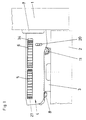
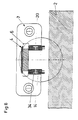
- the hinge according to the invention has a hinge arm 4 which, via articulated levers 17, 18 with a hinge cup 7 connected is.
- the hinge cup 7 is inserted into a bore in a furniture door 1.
- the base plate 3 is fastened to a furniture side wall 2, for example by means of dowels.
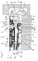
- a pin 10 is provided, which is transverse to Intermediate piece 13 and extends to the base plate 3 and in the notch 23 in the mounting position the base plate 3 is included. This is the intermediate piece 13 and thus that Intermediate piece 14 and the hinge arm 4 are held on the base plate 3 without play.
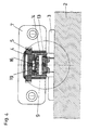
- a disk 19 On the intermediate piece 14 is a disk 19, which is on its underside with a spiral extending groove 24 is provided. In this groove, a pin 16 protrudes, which on the intermediate piece 13 is attached. The pin 16 projects through a slot 25 in the intermediate piece 14.
- the disk 19 is designed as a hexagon and has a wheel 5 positively connected.
- the wheel 5 has a corrugation 26 on the outside, which prevents twisting the wheel 5 relieved.
- the wheel 5 protrudes through openings 27 in the two Side bars of the hinge arm 4.
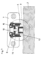
- the hinge arm 4 is at its front end in the usual way with a Adjusting screw 12 for the lateral adjustment of the hinge arm 4, the Adjusting screw 12 is held in a nut thread 28 of the hinge arm 4 and with its head 29 engages behind the two intermediate pieces 13, 14.
- the neck 30 of the Adjustment screw 28 protrudes through slots 31, 32 of the intermediate pieces which are open towards the front 13, 14.
- the neck 30 of the adjusting screw 12 is held in a driver 15 in a rotationally fixed manner.
- the Driver 15 is designed like the disk 19 as a hexagon and is by a wheel 6 surrounded form-fitting.
- the wheel 6, like the wheel 5, has a corrugation 33 on the outside the rotation of the wheel 6 facilitates and protrudes through openings 34 in the hinge arm 4th
- the adjusting screw 12 is rotated and thus the Hinge arm 4 in a conventional manner either moved closer to the base plate 3 or from this lifted off.
- the intermediate pieces 13, 14 are near their front end with laterally projecting Provide pins 20 which protrude into slots 34 in the side webs of the hinge arm 4.
- pins 20 which protrude into slots 34 in the side webs of the hinge arm 4.
Abstract
Description
Die Erfindung bezieht sich auf ein Scharnier mit einem vorzugsweise mittels eines Zwischenstückes werkzeuglos auf einer Grundplatte verankerbaren Scharnierarm, der über Gelenkhebel od.dgl. mit einem türseitigen Anschlagteil, beispielsweise einem Scharniertopf verbunden ist, wobei Verstelleinrichtungen vorgesehen sind, mittels denen die Position des Scharnierarmes relativ zum Zwischenstück in der Richtung der Tiefe des Möbels und/oder zur Seite des Möbels verstellbar ist.The invention relates to a hinge with a preferably by means of a Intermediate piece hinge arm that can be anchored to a base plate without tools Articulated lever or the like with a door-side stop part, for example a hinge cup is connected, wherein adjustment devices are provided, by means of which the position of the Hinge arm relative to the intermediate piece in the direction of the depth of the furniture and / or is adjustable to the side of the furniture.
Ein derartiges Scharnier ist aus der WO 86/02402 bekannt. Bei der Montage der Möbeltüre genügt es, den mit dem Zwischenstück versehenen Scharnierarm über das Zwischenstück in die Grundplatte einzuhängen und zur Möbelseitenwand zu kippen, worauf dieser automatisch auf der Grundplatte arretiert wird. Die Montage des Scharnierarmes auf der Grundplatte und die Demontage können werkzeuglos erfolgen. Für die Verstellung der Position des Scharnierarmes relativ zur Grundplatte in der Richtung der Tiefe des Möbels und seitlich zur Möbelseitenwand benötigt man einen Scharubenzieher.Such a hinge is known from WO 86/02402. When assembling the furniture door it suffices to place the hinge arm with the intermediate piece over the intermediate piece hang in the base plate and tilt to the furniture side wall, whereupon this is automatically locked onto the base plate. The assembly of the hinge arm on the Base plate and disassembly can be done without tools. For the adjustment of the Position of the hinge arm relative to the base plate in the direction of the depth of the furniture and to the side of the furniture side wall you need a scraper.
Aus dem deutschen Gebrauchsmuster 69 40 349 ist ein Scharnier mit einem auf einer Grundplatte verankerbaren Scharnierarm bekannt, wobei in der Montageplatte eine manuell verdrehbare Regelschraube gelagert ist. Um die Position des Scharnierarmes relativ zur Montageplatte zu verstellen, muß jedoch eine Schraube, mittels der der Scharnierarm auf der Montageplatte fixiert ist, gelöst werden. Nach erfolgter Einstellung der Regelschraube muß die Schraube, die den Scharnierarm hält, wieder angezogen werden.From the German utility model 69 40 349 is a hinge with one on one Base plate anchored hinge arm known, one in the mounting plate manually rotatable control screw is mounted. To the position of the hinge arm relative to To adjust the mounting plate, however, a screw must be used to open the hinge arm the mounting plate is fixed. After adjusting the regulating screw the screw holding the hinge arm must be tightened again.
Aufgabe der Erfindung ist es, ein Scharnier der eingangs erwähnten Art dahingehend zu verbessern, daß die Position des Scharnierarmes auf der Grundplatte werkzeuglos verstellt werden kann, und zwar ohne daß der Scharnierarm vor der Verstellung gelöst und anschließend wieder geklemmt werden muß.The object of the invention is to provide a hinge of the type mentioned improve that the position of the hinge arm on the base plate is adjusted without tools can be, without the hinge arm released before the adjustment and must then be clamped again.
Die erfindungsgemäße Aufgabe wird dadurch gelöst, daß die Verstelleinrichtungen je eine Handhabe aufweisen, mit der die Position des Scharnierarmes relativ zum Zwischenstück werkzeuglos verstellbar ist, wobei der Scharnierarm und/oder ein weiteres Zwischenstück von den Verstelleinrichtungen formschlüssig gehalten ist.The object of the invention is achieved in that the adjusting devices each have one Have handle with which the position of the hinge arm relative to the intermediate piece is adjustable without tools, the hinge arm and / or another intermediate piece is positively held by the adjusting devices.
Ein vorteilhaftes Ausführungsbeispiel der Erfindung sieht vor, daß die Handhabe von einem Rad gebildet wird, das durch je eine Durchbrechung in den beiden Seitenstegen des mit U-Profil ausgeführten Scharnierarmes ragt. Ein derartiges Rad kann leicht manuell gedreht werden.An advantageous embodiment of the invention provides that the handle of one Wheel is formed by an opening in each of the two side webs of the U-profile executed hinge arm protrudes. Such a wheel can easily be turned manually become.
Vorzugsweise sind die Verstelleinrichtungen als selbstklemmende Stelltriebe ausgebildet.The adjusting devices are preferably designed as self-locking actuators.
Ein weiteres Ausführungsbeispiel der Erfindung sieht vor, daß die Verstelleinrichtung eine Scheibe mit einer spiralförmigen Nut aufweist, wobei zu der Nut ein am Zwischenstück angeordneter Zapfen ragt, sodaß bei Drehung der Scheibe der Scharnierarm relativ zum Zwischenstück in der Richtung der Tiefe des Möbels verschoben wird.Another embodiment of the invention provides that the adjusting device Has disc with a spiral groove, with a groove on the intermediate piece arranged pin protrudes so that when the disc rotates the hinge arm relative to Intermediate piece is moved in the direction of the depth of the furniture.
Ein weiteres Ausführungsbeispiel der Erfindung sieht vor, daß die Handhabe, vorzugsweise ein Rad mit einer in einem Muttergewinde des Scharnierarmes gelagerten Verstellschraube gekuppelt ist, die der Seitenverstellung des Scharnierarmes dient und die mit deren Kopf in das Zwischenstück eingehängt ist, wobei zwischen der Verstellschraube und der Handhabe vorteilhaft ein separater Mitnehmer angeordnet ist.Another embodiment of the invention provides that the handle, preferably a wheel with an adjusting screw mounted in a nut thread of the hinge arm is coupled, which serves for the lateral adjustment of the hinge arm and which with its head in the intermediate piece is hooked in, between the adjusting screw and the handle a separate driver is advantageously arranged.
Nachfolgend wird ein Ausführungsbeispiel der Erfindung anhand der Figuren der beiliegenden Zeichnungen eingehend beschrieben.An exemplary embodiment of the invention is described below with reference to the figures in FIG accompanying drawings described in detail.
Es zeigen:
Wie aus den Figuren der Zeichnungen ersichtlich, weist das erfindungsgemäße Scharnier
einen Scharnierarm 4 auf, der über Gelenkhebel 17, 18 mit einem Scharniertopf 7
verbunden ist. Der Scharniertopf 7 ist in eine Bohrung einer Möbeltüre 1 eingesetzt.As can be seen from the figures of the drawings, the hinge according to the invention has
a
Die Grundplatte 3 ist an einer Möbelseitenwand 2 befestigt, beispielsweise mittels Dübeln. The
Im gezeigten Ausführungsbeispiel sind in den mit U-Profil ausgeführten Scharnierarm 4 zwei
ineinandergeschobene Zwischenstücke 13, 14 eingesetzt. Bei der Montage der Türe 1 sind
die Zwischenstücke 13, 14 im Scharnierarm 4 montiert.In the exemplary embodiment shown there are two in the
Zum Befestigen der Türe 1 an der Seitenwand 2 wird der Scharnierarm 4 mit der Achse 11
des Zwischenstückes 13 in die Grundplatte 3 eingehängt und anschließend gekippt, bis der
auf einer Achse drehbar gelagerte Kipphebel 8 mit seinem Vorsprung 21 hinter der Nase 22
am hinteren Ende der Grundplatte 3 einrastet. Dadurch ist das Zwischenstück 13 und mit
ihm das Zwischenstück 14 und der Scharnierarm 4 auf der Grundplatte 3 verankert. In etwa
der Mitte des Zwischenstückes 13 ist ein Stift 10 vorgesehen, der sich quer zum
Zwischenstück 13 und zur Grundplatte 3 erstreckt und der in Montagelage in einer Kerbe 23
der Grundplatte 3 aufgenommen ist. Dadurch ist das Zwischenstück 13 und somit das
Zwischenstück 14 und der Scharnierarm 4 spielfrei auf der Grundplatte 3 gehalten.To attach the door 1 to the
Am Zwischenstück 14 lagert eine Scheibe 19, die an ihrer Unterseite mit einer spiralförmig
verlaufenden Nut 24 versehen ist. In diese Nut ragt ein Zapfen 16, der am Zwischenstück 13
befestigt ist. Der Zapfen 16 ragt dabei durch einen Schlitz 25 im Zwischenstück 14.On the
Die Scheibe 19 ist im Ausführungsbeispiel als Sechskant ausgebildet und mit einem Rad 5
formschlüssig verbunden. Das Rad 5 weist außen eine Riffelung 26 auf, die das Verdrehen
des Rades 5 erleichtert. Das Rad 5 ragt dabei durch Durchbrechungen 27 in den beiden
Seitenstegen des Scharnierarmes 4.In the exemplary embodiment, the
Der Scharnierarm 4 ist bei seinem vorderen Ende in üblicher Weise mit einer
Verstellschraube 12 für die Seitenverstellung des Scharnierarmes 4 versehen, wobei die
Verstellschraube 12 in einem Muttergewinde 28 des Scharnierarmes 4 gehalten ist und mit
ihrem Kopf 29 die beiden Zwischenstücke 13, 14 hintergreift. Der Hals 30 der
Verstellschraube 28 ragt dabei durch nach vorne offene Schlitze 31, 32 der Zwischenstücke
13, 14.The
Der Hals 30 der Verstellschraube 12 ist in einem Mitnehmer 15 drehfest gehalten. Der
Mitnehmer 15 ist wie die Scheibe 19 als Sechskant ausgeführt und wird von einem Rad 6
formschlüssig umgeben. Das Rad 6 weist wie das Rad 5 außen eine Riffelung 33 auf, die
das Verdrehen des Rades 6 erleichtert und ragt durch Durchbrechungen 34 im Scharnierarm
4. The
Durch Verdrehen des Rades 6 wird die Verstellschraube 12 gedreht und somit der
Scharnierarm 4 in herkömmlicher Weise entweder näher zur Grundplatte 3 bewegt oder von
dieser abgehoben.By turning the
Bei der Verdrehung des Rades 5 bewirkt die zwangsläufige Verdrehung der Scheibe 19
durch die Führung des Zapfens 16 in der Nut 24 eine Relativbewegung zwischen dem
Zwischenstück 13 und dem Zwischenstück 14 und somit eine lineare Verstellung des
Scharnierarmes 4 in der Richtung der Tiefe des Möbels.When the
Die Zwischenstücke 13, 14 sind nahe ihrem vorderen Ende mit seitlich auskragenden
Zapfen 20 versehen, die in Schlitze 34 in den Seitenstegen des Scharnierarmes 4 ragen.
Durch die Zapfen 20 und die Schlitze 34 wird der Verstellbereich des Scharnierarmes 4 in
seitlicher Richtung, d.h. in einer Ebene senkrecht zur Möbelseitenwand begrenzt.The
Claims (12)
Applications Claiming Priority (2)
| Application Number | Priority Date | Filing Date | Title |
|---|---|---|---|
| AT137998 | 1998-08-11 | ||
| AT0137998A AT407277B (en) | 1998-08-11 | 1998-08-11 | HINGE |
Publications (2)
| Publication Number | Publication Date |
|---|---|
| EP0979917A2 true EP0979917A2 (en) | 2000-02-16 |
| EP0979917A3 EP0979917A3 (en) | 2003-04-16 |
Family
ID=3512612
Family Applications (1)
| Application Number | Title | Priority Date | Filing Date |
|---|---|---|---|
| EP99114727A Withdrawn EP0979917A3 (en) | 1998-08-11 | 1999-07-24 | Hinge |
Country Status (4)
| Country | Link |
|---|---|
| US (1) | US6233783B1 (en) |
| EP (1) | EP0979917A3 (en) |
| AT (1) | AT407277B (en) |
| BR (1) | BR9903545A (en) |
Cited By (2)
| Publication number | Priority date | Publication date | Assignee | Title |
|---|---|---|---|---|
| EP1990493A1 (en) | 2007-05-07 | 2008-11-12 | Heinrich J. Kesseböhmer KG | Fixing device for a pivoting furniture component |
| EP2949847A1 (en) * | 2014-05-27 | 2015-12-02 | Grass GmbH & Co. KG | Adjustable control lever |
Families Citing this family (5)
| Publication number | Priority date | Publication date | Assignee | Title |
|---|---|---|---|---|
| AT501396B1 (en) * | 2004-10-28 | 2007-10-15 | Blum Gmbh Julius | FALTTÜRENSCHARNIER |
| AT503839B1 (en) * | 2006-07-03 | 2010-02-15 | Lautenschlaeger Mepla Werke | FURNITURE HINGE |
| KR20100019616A (en) * | 2008-08-11 | 2010-02-19 | 삼성전자주식회사 | Refrigerator |
| DE202011101342U1 (en) * | 2011-05-25 | 2012-08-27 | Prämeta GmbH & Co. KG | hinge |
| JP6013588B2 (en) * | 2013-11-11 | 2016-10-25 | スガツネ工業株式会社 | Hinge device and hinge device base |
Citations (2)
| Publication number | Priority date | Publication date | Assignee | Title |
|---|---|---|---|---|
| DE6940349U (en) | 1969-10-15 | 1970-01-22 | Ewald Schulte Fa | CONCEALED HINGES FOR THE LEAVES OF DOORS, IN PARTICULAR FURNITURE DOORS |
| WO1986002402A1 (en) | 1984-10-19 | 1986-04-24 | Julius Blum Gesellschaft M.B.H. | Hinge |
Family Cites Families (10)
| Publication number | Priority date | Publication date | Assignee | Title |
|---|---|---|---|---|
| FR817184A (en) * | 1937-02-01 | 1937-08-27 | Improvements to door hinges | |
| IT8120844V0 (en) * | 1980-02-26 | 1981-02-19 | Blum Gmbh Julius | HEIGHT ADJUSTABLE HINGE. |
| DE3241284A1 (en) * | 1982-11-09 | 1984-05-10 | Paul Hettich & Co, 4983 Kirchlengern | FURNITURE HINGE |
| DE3624237A1 (en) * | 1986-03-06 | 1987-09-10 | Grass Alfred Metallwaren | HINGE TAPE WITH EASILY DETACHABLE FASTENING OF THE FURNITURE-SIDED COVER BRACKET ON THE FURNITURE PART |
| DE8911169U1 (en) * | 1989-09-19 | 1990-10-18 | Licentia Patent-Verwaltungs-Gmbh, 6000 Frankfurt, De | |
| DE69012986T2 (en) * | 1989-12-25 | 1995-01-26 | Murakoshi Seiko Koganei Kk | HINGE. |
| AT398801B (en) * | 1990-05-16 | 1995-02-27 | Blum Gmbh Julius | HINGE |
| AT1214U1 (en) * | 1995-12-18 | 1996-12-27 | Blum Gmbh Julius | HINGE |
| US5799370A (en) * | 1996-06-12 | 1998-09-01 | The Stanley Works | Adjustable hinge |
| TW363106B (en) * | 1997-02-25 | 1999-07-01 | Sugatsune Kogyo | Twisting chain |
-
1998
- 1998-08-11 AT AT0137998A patent/AT407277B/en active
-
1999
- 1999-07-24 EP EP99114727A patent/EP0979917A3/en not_active Withdrawn
- 1999-08-09 US US09/370,242 patent/US6233783B1/en not_active Expired - Fee Related
- 1999-08-10 BR BR9903545-6A patent/BR9903545A/en not_active Application Discontinuation
Patent Citations (2)
| Publication number | Priority date | Publication date | Assignee | Title |
|---|---|---|---|---|
| DE6940349U (en) | 1969-10-15 | 1970-01-22 | Ewald Schulte Fa | CONCEALED HINGES FOR THE LEAVES OF DOORS, IN PARTICULAR FURNITURE DOORS |
| WO1986002402A1 (en) | 1984-10-19 | 1986-04-24 | Julius Blum Gesellschaft M.B.H. | Hinge |
Cited By (2)
| Publication number | Priority date | Publication date | Assignee | Title |
|---|---|---|---|---|
| EP1990493A1 (en) | 2007-05-07 | 2008-11-12 | Heinrich J. Kesseböhmer KG | Fixing device for a pivoting furniture component |
| EP2949847A1 (en) * | 2014-05-27 | 2015-12-02 | Grass GmbH & Co. KG | Adjustable control lever |
Also Published As
| Publication number | Publication date |
|---|---|
| BR9903545A (en) | 2000-08-29 |
| US6233783B1 (en) | 2001-05-22 |
| ATA137998A (en) | 2000-06-15 |
| AT407277B (en) | 2001-02-26 |
| EP0979917A3 (en) | 2003-04-16 |
Similar Documents
| Publication | Publication Date | Title |
|---|---|---|
| EP0868586B1 (en) | Hinge | |
| EP0349018B1 (en) | Hinge | |
| AT391344B (en) | Hinge | |
| EP0437750B1 (en) | Fitting plate for fitting a hinge arm | |
| EP1812674A1 (en) | Actuator | |
| AT409157B (en) | HINGE | |
| EP0225609B1 (en) | Hinge | |
| WO2002024387A9 (en) | Chip removing tool | |
| EP0453829A1 (en) | Hinge | |
| EP2297418B1 (en) | Hinge | |
| EP1028213A2 (en) | Device for mounting a fitting element, preferably a support arm of a hinge, to a furniture wall | |
| AT409288B (en) | FURNITURE HINGE | |
| AT501658B1 (en) | DEVICE FOR FASTENING A WINDOW FRAME BY MEANS OF A ADJUSTING SCREW | |
| AT407277B (en) | HINGE | |
| EP0702386B1 (en) | Pivotable actuator for a safety switch | |
| EP0708219A1 (en) | Fitting or the like, preferably hinge part, with fastening device | |
| WO2006024374A1 (en) | Mounting plate for adjustably retaining furniture hinges on the frame of pieces of furniture | |
| DE19809251A1 (en) | Rosette for a door fitting | |
| EP0392570B1 (en) | Hinge | |
| EP0760890B1 (en) | Multipart hinge | |
| EP1093751A2 (en) | Device for the mounting of a swingable apparatus | |
| DE4345069C1 (en) | Articulated-arm awning | |
| DE2722108C2 (en) | Support wall stop part for furniture hinges | |
| EP1241308A2 (en) | Adjusting device of a hinge | |
| EP0711632A1 (en) | Clamping device |
Legal Events
| Date | Code | Title | Description |
|---|---|---|---|
| PUAI | Public reference made under article 153(3) epc to a published international application that has entered the european phase |
Free format text: ORIGINAL CODE: 0009012 |
|
| AK | Designated contracting states |
Kind code of ref document: A2 Designated state(s): AT BE CH CY DE DK ES FI FR GB GR IE IT LI LU MC NL PT SE |
|
| AX | Request for extension of the european patent |
Free format text: AL;LT;LV;MK;RO;SI |
|
| PUAL | Search report despatched |
Free format text: ORIGINAL CODE: 0009013 |
|
| AK | Designated contracting states |
Designated state(s): AT BE CH CY DE DK ES FI FR GB GR IE IT LI LU MC NL PT SE |
|
| AX | Request for extension of the european patent |
Extension state: AL LT LV MK RO SI |
|
| STAA | Information on the status of an ep patent application or granted ep patent |
Free format text: STATUS: THE APPLICATION IS DEEMED TO BE WITHDRAWN |
|
| 18D | Application deemed to be withdrawn |
Effective date: 20030202 |