EP0979904A2 - Anordnung zum Schnelleinbau eines Wasserhahnes - Google Patents
Anordnung zum Schnelleinbau eines Wasserhahnes Download PDFInfo
- Publication number
- EP0979904A2 EP0979904A2 EP99115862A EP99115862A EP0979904A2 EP 0979904 A2 EP0979904 A2 EP 0979904A2 EP 99115862 A EP99115862 A EP 99115862A EP 99115862 A EP99115862 A EP 99115862A EP 0979904 A2 EP0979904 A2 EP 0979904A2
- Authority
- EP
- European Patent Office
- Prior art keywords
- nut
- threaded
- deck
- retainer
- mounting hole
- Prior art date
- Legal status (The legal status is an assumption and is not a legal conclusion. Google has not performed a legal analysis and makes no representation as to the accuracy of the status listed.)
- Withdrawn
Links
Images




Classifications
-
- E—FIXED CONSTRUCTIONS
- E03—WATER SUPPLY; SEWERAGE
- E03C—DOMESTIC PLUMBING INSTALLATIONS FOR FRESH WATER OR WASTE WATER; SINKS
- E03C1/00—Domestic plumbing installations for fresh water or waste water; Sinks
- E03C1/02—Plumbing installations for fresh water
- E03C1/04—Water-basin installations specially adapted to wash-basins or baths
- E03C1/042—Arrangements on taps for wash-basins or baths for connecting to the wall
-
- E—FIXED CONSTRUCTIONS
- E03—WATER SUPPLY; SEWERAGE
- E03C—DOMESTIC PLUMBING INSTALLATIONS FOR FRESH WATER OR WASTE WATER; SINKS
- E03C1/00—Domestic plumbing installations for fresh water or waste water; Sinks
- E03C1/02—Plumbing installations for fresh water
- E03C1/04—Water-basin installations specially adapted to wash-basins or baths
- E03C1/0401—Fixing a tap to the sanitary appliance or to an associated mounting surface, e.g. a countertop
- E03C1/0402—Fixing a tap to the sanitary appliance or to an associated mounting surface, e.g. a countertop with mounting from only one side
-
- E—FIXED CONSTRUCTIONS
- E03—WATER SUPPLY; SEWERAGE
- E03C—DOMESTIC PLUMBING INSTALLATIONS FOR FRESH WATER OR WASTE WATER; SINKS
- E03C1/00—Domestic plumbing installations for fresh water or waste water; Sinks
- E03C1/02—Plumbing installations for fresh water
- E03C1/04—Water-basin installations specially adapted to wash-basins or baths
- E03C1/0401—Fixing a tap to the sanitary appliance or to an associated mounting surface, e.g. a countertop
-
- Y—GENERAL TAGGING OF NEW TECHNOLOGICAL DEVELOPMENTS; GENERAL TAGGING OF CROSS-SECTIONAL TECHNOLOGIES SPANNING OVER SEVERAL SECTIONS OF THE IPC; TECHNICAL SUBJECTS COVERED BY FORMER USPC CROSS-REFERENCE ART COLLECTIONS [XRACs] AND DIGESTS
- Y10—TECHNICAL SUBJECTS COVERED BY FORMER USPC
- Y10T—TECHNICAL SUBJECTS COVERED BY FORMER US CLASSIFICATION
- Y10T137/00—Fluid handling
- Y10T137/9464—Faucets and spouts
Definitions
- the present invention relates generally to a faucet assembly, and more particularly, to a quick install faucet assembly which can be mounted from the top of a deck to which the faucet assembly is connected.
- the mounting of the faucet assembly is completed from, or requires assembly components to be installed from the underside of the deck to which the faucet assembly is mounted.
- the assembly which is typically required to be performed from the underside of the deck is often awkward and uncomfortable for the installer.
- an apparatus for installing a fixture on a top side of a deck having at least one mounting hole therein comprising:
- the retaining bracket includes at least one leg and a cross bar formed at one end thereof to extend substantially at a right angle thereto;
- the at least one leg has the end thereof with the crossbar pivoted upwardly and engageable with the threaded member to permit passage of the retaining member through the mounting hole.
- the crossbar may limit the raising and the lowering of the at least one leg to prevent excess pivotal movement of the at least one leg in either direction.
- the retaining bracket is formed in a substantial "U" shape with a pair of legs extending on opposite sides of the nut and a crossbar connected across one end of the legs such that the crossbar limits movement of the retaining bracket and permits passage of the retaining member through the mounting hole. Additionally the retaining bracket may be pivoted upwardly to define an "U" shape for passage through the mounting hole.
- a faucet comprising:
- an end body valve assembly for use with a faucet, comprising:
- the quick install faucet assembly described herein includes a spout 10 and a pair of separately mounted end body valve assemblies 12, 14.
- the principles of the present invention may also be applied to a faucet assembly having the spout 10 and valve assemblies 12, 14 as a single unit.
- the spout 10 includes a water passage 16 which communicates with a waterway tube 18.
- the waterway tube 18 has a threaded end portion 20 which engages an internally threaded portion 22 of the spout 10.
- the waterway tube 18 includes a radially extending hexagonal flange portion 24.
- a guide bracket 26 is provided with a pair of openings 28, as shown in Figure 10, and receives the threaded portion 20 of the waterway tube 18 through one of the openings 28.
- the radially extending flange portion 24 supports the guide bracket 26 within a lower cavity 30 defined within the spout 10.
- the threaded portion 20 of waterway tube 18 is engaged with the internally threaded portion 22 of spout 10.
- a Teflon® tape, or other seal means can be provided on the threaded portion 20 of the waterway tube 18 in order to provide a water sealed fit.
- a threaded rod 32 is provided with a hollow cylindrical body 34 which is externally threaded and is provided with an upper radially extending flange 36.
- the threaded rod 32 extends through the second opening 28 in guide bracket 26 while flange 36 rests against the guide bracket 26.
- the threaded rod 32 is aligned with an opening 38 in the spout 10 which allows access of an allen wrench for engaging an internal hexagonal engagement portion 40 provided in the upper portion of the threaded rod 32.
- a pop-up rod 58 extends through the central opening of the threaded rod 32 and through the opening 38 in spout 10. As is well known in the art, the pop-up rod 58 engages a drain stopper assembly (not shown) for opening and closing the drain stopper.
- a nut member 42 is threadedly engaged with the threaded rod 32.
- the nut member 42 includes a threaded opening 44 which engages the threaded rod 32 and a second opening 46 which slidably receives the waterway tube 18.
- the nut member 42 also includes two pivot arms 48 which extend from opposite sides of the nut member 42.
- a retainer member 50 is pivotally mounted to the nut member 42.
- the retainer member 50 includes a pair of generally parallel arms 52 having centrally located pivot openings 54.
- a cross bar 56 extends between the arms 52 as best shown in Figure 9.
- the pivot arms 48 of nut member 42 extend through pivot openings 54 of retainer member 50 for pivotally supporting the retainer member 50 thereon.
- the nut member 42 can be modified to include a pivot pin extending therethrough for supporting the retainer member 50.
- the spout is mounted to a deck or mounting surface 60 which is provided with an opening 62 for receiving the threaded rod 32 and waterway tube 18 of the spout assembly.
- the retainer member 50 is pivoted to a generally vertical position extending longitudinally with the waterway tube 18 and threaded rod 32 such that the cross bar 56 rests against the waterway tube 18.
- the spout assembly can be optionally tilted counter clockwise, as shown in Figure 3, so that the cross bar 56 of the retainer member 50 is stable against the waterway tube 18. Otherwise, the installer can hold the retainer member 50 in the vertical position upon insertion through the opening 62.
- the weight of the cross bar portion 56 of the retainer member 50 causes the retainer member 50 to rotate in a direction of arrow A, as shown in Figure 3, until the cross bar 56 contacts the waterway tube 18 in a generally horizontal position as shown in Figure 5.
- an allen wrench can be inserted through the opening 38 in the spout 10 to engage the hexagonal portion 40 of the threaded rod 32.
- the threaded rod 32 can then be turned in order to draw the nut member 42 and retainer member 50 in an upward direction so that the end portions of the parallel arms 52 of the retainer member 50 engage the underside of the deck 60 at four points spaced about opening 62, as best shown in Figure 2.
- the pop-rod 58 is slidably received in the opening in the threaded rod 32 and can be easily removed so that the allen wrench can be inserted through the opening 38 of spout 10 to engage the hexagonal portion 48 of the threaded rod 32.
- the quick install faucet assembly of the present invention is provided with first and second end body valve assemblies 12, 14.
- One of the end body valve assemblies 12 is provided for the hot water line while the other of the end body valve assemblies 14 is for the cold water supply line.
- Each end body valve assembly 12, 14 is provided with an end connector 70, secured in place by a connector clip 72, for communicating water via interconnecting hoses 74 to the T-joint connector 76 mounted to the waterway tube 18 of spout assembly 10.
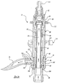
- the end body valve assembly 14 includes a threaded body 80 mounted to a shut-off valve 82.
- the threaded body 80 includes an upper hexagonal head portion 84 provided with a radially extending flange 86 below the hexagonal head portion 84.
- the threaded body 80 also includes a hollow longitudinally extending base portion 88 which defines the waterflow path as best shown in Figure 16.
- the threaded body 80 has a hollow central portion 90 which receives a spacer tube 92 (shown in Figure 20).
- Spacer tube 92 has a hollow opening therethrough which defines the central flowpath 93 which communicates fluid through the shut-off-valve 82.
- the shut-off valve 82 communicates water from the waterflow path 93 to a concentrically formed waterflow path 95 between the threaded body 80 and spacer tube 92 to communicate water to radially extending openings 96 in the base portion 88 of the threaded body 80.
- the openings 96 communicate with the end connector 70 for communicating fluid through the interconnecting hose 74.
- the base portion 88 of threaded body 80 is provided with radial grooves 98 for supporting O-rings 102 between the base portion 88 and the end connector 70 for providing a water-tight fit between the end connector 70 and the threaded body 80.
- the base portion 88 of the threaded body 80 includes a recessed area between the O-rings 102 for water flow.
- the base portion 88 also includes a groove 104 for receiving a retaining clip 72, as shown in Figure
- a threaded nut 110 is threadedly engaged with the threaded body 80.
- Threaded nut 110 as best shown in Figure 18, is provided with a pair of oppositely disposed guide recesses 112 and a pair of oppositely disposed pivot arms 114.
- a pivoting retainer 118 as best shown in Figure 17, is pivotally mounted to the threaded nut 110.
- the pivoting retainer 118 includes a pair of generally parallel arms 120 each provided with a pivot opening 122 for receiving the pivot arms 114 for pivotally supporting the retainer member 118 to the threaded nut 110.
- the retainer member 118 includes a cross bar portion 124 which extends between the arms 120.
- a nut guide assembly 130 is provided for guiding the threaded nut 110 and preventing rotation of the threaded nut 110.
- the nut guide assembly 130 includes a guide flange 132 which abuts against the radially extending flange 86 of threaded body 80.
- guide flange 132 includes a pair of recesses 134 which mate with an upper bend portion 136 of oppositely disposed guide arms 138, as best shown in Figures 23 and 24. As the guide flange 132 rests against the radially extending flange 86, the flange 86 helps to hold the upper bend portion 136 of the arms 138 in the recesses 134.
- the guide arms 138 extend through the guide recesses 112 in the threaded nut 110 to prevent the threaded nut 110 from rotating relative to the nut guide assembly 130. Accordingly, as the threaded body 80 is rotated, the threaded nut 110 is prevented from rotating relative to the nut guide assembly 130 therefore causing the threaded nut 110 to move upward and downward along the threaded body 80 depending upon the direction of rotation of the threaded body 80. As the threaded nut 110 moves up and down along the threaded body 80 upon rotation of the threaded body 80, the retainer member 118 moves therewith.
- the retainer member 118 is pivoted to the generally vertical position as best shown in Figure 11-13.
- the end body valve assembly 14 is then inserted through an opening 150 in the deck or mounting surface 60.
- the retainer member 118 will rotate to a horizontal position as best shown in Figures 14 and 15.
- the rotation of the retainer member 118 is due to the mass imbalance of the retainer member 118 caused by one end of the retainer member 118 being heavier than the other due to the weight of the cross bar 124.
- the guide flange 132 is held and the threaded body 80 is rotated in a clockwise direction in order to draw the retainer member 118 upward against the underside of the deck 60.
- a wrench can be used to engage the hexagonal head portion 84 of the threaded body 80 in order to tighten the end body valve assembly 14 in place.
- the height is automatically set for proper handle height.
- a lever handle (not shown) would then be applied to the upper splined portion 154 of the valve 82 as is known in the art.
- the end connector 70 is attached to the end body valve assembly 14 by sliding the connector 70 over the base portion 88 of the threaded body 80 and the connector clip 72 is inserted in the groove 104 for holding the connector 70 in place.
- the interconnecting hoses 74 are preassembled to the end connectors 70 and T-connector 76, thus reducing the amount of time and work done under the sink where space is limited.
- the end connector 70 includes a generally cylindrical body portion 160 having a radially extending port neck 162 extending therefrom. Port neck 162 includes serrations 164 on an exterior surface thereof. The serrations 164 engage with the hose 74 to secure the hose 74 to the end connector 70.
- the connector 70 can be held in place by a threaded connector 230 which engages a groove 232 formed in the base portion 234 of a modified threaded body 236.
- the threaded connector 230 includes a main body portion 238 which receives a connector ring 240 provided with a plurality of fingers 242 with radially inwardly extending end portions 244.
- the interior walls 246 of the main body portion 238 are sloped so as to provide a cam for maintaining the fingers 242 engaged with the groove 232 formed in the base portion 234 of the threaded body 236.
- the main body portion 238 of the threaded connector 230 includes a threaded portion 248 for connecting to a water supply line (not shown).
- This alternative embodiment simplifies the design of the modified threaded body 236, as compared to the threaded body 80, since the threaded portion 248, for connecting to the water supply line, is formed on the threaded connector 230 instead of the base portion 88 of the threaded body 80.
- the water supply line can be pre-assembled to the threaded connector 230 and the threaded connector 230 can then be simply pushed into place onto the modified threaded body 236 under the sink without the need for tools under the sink where space to work is limited.
- the threaded connector 230 is commercially available from the PARFLEX division of Parker Hannifin, 1300 N. Freedom Street, Ravenna, Ohio 44266, USA.
- the T-connector 76 shown in Figure 1, includes a body portion 168, as best shown in Figure 7, connected to the waterway tube 18 and further having first and second hose connector portions 170 for connecting with the hoses 74.
- the body portion 168 as shown in Figure 7, supports an O-ring 172 which surrounds the waterway tube 18 as well as a connector ring 174.
- the connector ring 174 includes a plurality of fingers 176 which extend longitudinally and are provided with radially inwardly extending end portions 178. The radially inwardly extending end portions 178 engage an annular groove 180 formed in the exterior surface of the waterway tube 18 in order to secure the T-connector 76, as best shown in Figure 1, to the waterway tube 18.
- the T-connector 76 is commercially available from the PARFLEX Division of Parker Hannifin, 1300 N. Freedom Street, Ravenna, Ohio 44266, USA.
- a modified T-connector 180 as shown in Figure 33, can be utilized.
- the T-connector 180 includes a body portion 182 including a cylindrical bore 184 for receiving the end of the waterway tube 186.
- the waterway tube 186 includes a threaded end portion 187 for mating with a threaded nut 188 for securing the T-connector 180 in place.
- the waterway tube 186 has a pair of grooves 190 which each receive an O-ring 192 for providing a watertight sealed relationship between said waterway tube 186 and the T-connector 180.
- the T-connector 180 includes a pair of serrated hose connector portions 194.
- the end body valve assembly 200 is attached to a sink or deck by an upper bracket 202 and a lower nut retainer 204, best shown in Figures 27-30.
- the upper bracket 202 is not threaded and is attached to a bracket 206.
- the bracket 206 includes a pair of long arms 208 with elongated slots 210.
- the lower nut retainer 204 has a pair of pivot arms 212 which extend laterally outward and includes a threaded body portion 214 and a pair of spaced retaining wall portions 216.
- the pivot arms 212 are slidably received in the elongated slots 210 of arms 208 such that the lower nut retainer 204 swivels between the two slots 210.
- the lower nut retainer 204 swings upward in a vertical position as shown in Figures 27 and 28 so that the lower nut retainer 204 and bracket 206 can be inserted through the opening 150 in the deck 60.
- the lower nut retainer 204 swings downward to a generally horizontal position due to gravity once the nut retainer 204 has passed through the opening 150.
- the retaining wall portions 216 of the lower nut retainer 204 in the horizontal orientation, extend over the edges of the opening 150.
- An end body 220 is then inserted through a centre of the upper bracket 202 and lowered to the lower nut retainer 204.
- the end body 220 includes a threaded outer surface 221 such that upon rotation of the end body 220, the end body 220 engages the lower nut retainer 204.
- the upper bracket 202 can be held in place while the threaded valve body 220 is rotated.
- the valve body rotation causes the lower nut retainer 204 to move up the threaded valve body 220 until the deck 60 is sandwiched by the upper bracket 202 and lower nut retainer 204.
- the end body 220 supports a valve 82 and an internal spacer tube 92 in the same manner as shown in Figure 16.
- the quick connect faucet assembly provides an installation which is much faster than conventional faucets. Furthermore, installation is simplified since all components are tightened from above the sink.
- the quick install faucet assembly of the present invention has no loose parts that can be misplaced.
- the end body and spout can be preassembled and ready for installation by the user.
Landscapes
- Life Sciences & Earth Sciences (AREA)
- Engineering & Computer Science (AREA)
- Hydrology & Water Resources (AREA)
- Public Health (AREA)
- Water Supply & Treatment (AREA)
- Health & Medical Sciences (AREA)
- Domestic Plumbing Installations (AREA)
- Valve Housings (AREA)
- Housings And Mounting Of Transformers (AREA)
- Pivots And Pivotal Connections (AREA)
- Furniture Connections (AREA)
- Standing Axle, Rod, Or Tube Structures Coupled By Welding, Adhesion, Or Deposition (AREA)
- Workshop Equipment, Work Benches, Supports, Or Storage Means (AREA)
Applications Claiming Priority (2)
| Application Number | Priority Date | Filing Date | Title |
|---|---|---|---|
| US133460 | 1998-08-13 | ||
| US09/133,460 US5946746A (en) | 1998-08-13 | 1998-08-13 | Quick install faucet assembly |
Publications (2)
| Publication Number | Publication Date |
|---|---|
| EP0979904A2 true EP0979904A2 (de) | 2000-02-16 |
| EP0979904A3 EP0979904A3 (de) | 2001-08-08 |
Family
ID=22458722
Family Applications (1)
| Application Number | Title | Priority Date | Filing Date |
|---|---|---|---|
| EP99115862A Withdrawn EP0979904A3 (de) | 1998-08-13 | 1999-08-12 | Anordnung zum Schnelleinbau eines Wasserhahnes |
Country Status (10)
| Country | Link |
|---|---|
| US (1) | US5946746A (de) |
| EP (1) | EP0979904A3 (de) |
| KR (1) | KR20000017257A (de) |
| CN (1) | CN1102982C (de) |
| AR (1) | AR020125A1 (de) |
| BR (1) | BR9903575A (de) |
| CA (1) | CA2280055C (de) |
| PE (1) | PE20000846A1 (de) |
| SG (1) | SG81295A1 (de) |
| TW (1) | TW400422B (de) |
Cited By (2)
| Publication number | Priority date | Publication date | Assignee | Title |
|---|---|---|---|---|
| KR101018882B1 (ko) | 2010-11-26 | 2011-03-04 | 주식회사 건축사사무소베스트 | 공동주택의 가변형 수전 브라켓트 |
| CN104806786A (zh) * | 2015-04-24 | 2015-07-29 | 雅鼎卫浴股份有限公司 | 一种阀芯隐藏式龙头 |
Families Citing this family (50)
| Publication number | Priority date | Publication date | Assignee | Title |
|---|---|---|---|---|
| US6138296A (en) * | 1999-06-23 | 2000-10-31 | Emhart Inc. | Easy connect and disconnect faucet spout assembly |
| US6220278B1 (en) | 2000-01-13 | 2001-04-24 | Kohler Co. | Top mounting faucet assembly |
| US6328059B1 (en) * | 2000-03-22 | 2001-12-11 | Alessandro Testori | Top mounted faucet assembly |
| US6209153B1 (en) | 2000-05-15 | 2001-04-03 | Emhart Inc. | Quick-install mounting nut assembly for a single control kitchen faucet |
| US6360770B1 (en) * | 2000-05-23 | 2002-03-26 | Moen Incorporated | Modular lavatory faucet spout mounting |
| US6256810B1 (en) * | 2000-06-16 | 2001-07-10 | Emhart Inc. | Easy connect and disconnect faucet spout assembly |
| US6631730B1 (en) | 2000-07-14 | 2003-10-14 | Emhart Inc. | Quick install faucet body |
| US6405749B1 (en) | 2000-07-14 | 2002-06-18 | Emhart Llc | Quick install faucet body |
| US6301728B1 (en) | 2000-08-02 | 2001-10-16 | Emhardt Inc. | Quick-install assembly for a single control faucet |
| US6385798B1 (en) | 2000-12-22 | 2002-05-14 | Moen Incorporated | Top mount faucet valve body |
| US6370712B1 (en) | 2000-12-22 | 2002-04-16 | Moen Incorporated | Top mount plumbing fixture |
| US6484330B2 (en) * | 2001-02-07 | 2002-11-26 | Kohler Co. | Combined faucet and drain assembly |
| US6434765B1 (en) | 2001-02-20 | 2002-08-20 | Moen Incorporated | Top mount plumbing fixture |
| US6571407B1 (en) * | 2001-03-16 | 2003-06-03 | Loren Skarie | Faucet retainers |
| ES2205964A1 (es) * | 2001-03-23 | 2004-05-01 | Industrias Ramon Soler, S.A. | Dispositivo de montaje para grifos. |
| US6421849B1 (en) * | 2001-07-25 | 2002-07-23 | Kohler Co. | Mounting assembly for plumbing control fitting |
| US6684906B2 (en) * | 2001-09-28 | 2004-02-03 | Moen Incorporated | Quick connect/disconnect water faucet conduit assembly |
| US7269864B2 (en) | 2002-04-17 | 2007-09-18 | Masco Corporation Of Indiana | Mounting system for a faucet |
| AU2003245241A1 (en) | 2002-04-17 | 2003-11-03 | Masco Corporation Of Indiana | Top down mounting system for faucet |
| JP3955495B2 (ja) * | 2002-05-01 | 2007-08-08 | Uro電子工業株式会社 | ワンタッチ取付形水栓 |
| US6668393B1 (en) | 2002-07-23 | 2003-12-30 | Moen Incorporated | Height adjustable diverter spout assembly |
| US7017600B2 (en) * | 2003-03-19 | 2006-03-28 | Clack Corporation | Faucet |
| WO2006042018A2 (en) * | 2004-10-07 | 2006-04-20 | Watts Regulator Co. | Top mounted faucet assembly with air gap |
| EP1877628A2 (de) * | 2005-03-14 | 2008-01-16 | Masco Corporation Of Indiana | Schnellwechselmontagesystem für einen wasserhahn |
| US7469880B2 (en) * | 2005-03-16 | 2008-12-30 | Green Ronald D | Quick connect feature for a fluid connection |
| US7882578B2 (en) * | 2005-06-01 | 2011-02-08 | Xiamen Lota International Co., Ltd. | Pop-up valve with seal |
| US7698755B2 (en) | 2005-08-29 | 2010-04-20 | Masco Corporation Of Indiana | Overhead cam faucet mounting system |
| US7661155B2 (en) * | 2006-10-26 | 2010-02-16 | Tsai-Chen Yang | Lateral driving faucet water outlet seat |
| US8407828B2 (en) | 2007-11-30 | 2013-04-02 | Masco Corporation Of Indiana | Faucet mounting system including a lift rod |
| EP2318597A4 (de) * | 2008-06-25 | 2014-06-18 | Masco Corp | Widespread-wasserhahn |
| US8231318B2 (en) * | 2009-04-22 | 2012-07-31 | As Ip Holdco, L.L.C. | Push and turn nut for quick faucet installation |
| CA2796796C (en) | 2010-05-21 | 2015-03-24 | Masco Corporation Of Indiana | Faucet mounting anchor |
| CN102261505A (zh) * | 2010-05-25 | 2011-11-30 | 骊住株式会社 | 自动水龙头 |
| GB201018074D0 (en) * | 2010-10-26 | 2010-12-08 | Kohler Mira Ltd | Tap mounting |
| US8156580B1 (en) | 2011-02-18 | 2012-04-17 | Paone Arthur J | Sink with cutout |
| US9376789B2 (en) | 2011-03-08 | 2016-06-28 | As Ip Holdco, Llc | Quick connection coupling |
| US8272083B1 (en) | 2011-04-20 | 2012-09-25 | Liston Thomas D | System and method for faucet installations |
| CN102287574A (zh) * | 2011-05-24 | 2011-12-21 | 徐建侠 | 一种水龙头固定结构 |
| WO2013013185A1 (en) | 2011-07-21 | 2013-01-24 | Kohler Co. | Quick connector for faucet |
| CA2846254C (en) | 2011-08-24 | 2019-09-17 | As Ip Holdco, Llc | No-tools spread faucet assembly, kits and methods |
| CN204690849U (zh) * | 2015-01-22 | 2015-10-07 | 成霖企业股份有限公司 | 水龙头总成 |
| US9702126B1 (en) * | 2015-03-04 | 2017-07-11 | Timothy A. Feher | Faucet stepped legs and assembly method |
| CN104930223A (zh) * | 2015-06-09 | 2015-09-23 | 华尔达(厦门)塑胶有限公司 | 可快速更换的水龙头 |
| ITUB20153967A1 (it) * | 2015-09-14 | 2017-03-14 | Vincenzo Magistro | Rubinetto ad installazione superiore |
| KR20180090880A (ko) * | 2016-05-30 | 2018-08-13 | 플로우테크 키친 앤 배쓰룸 테크놀로지 컴퍼니 리미티드 | 상부 장착 장치 |
| FR3077585B1 (fr) * | 2018-02-06 | 2022-08-05 | Sergio Lischetti | Element de robinetterie et equipement sanitaire le comprenant |
| US11001994B2 (en) | 2018-09-27 | 2021-05-11 | Delta Faucet Company | Reduced profile faucet handle assembly |
| US11702823B2 (en) * | 2018-11-15 | 2023-07-18 | Spectrum Brands, Inc. | Top-mount faucet |
| CN113854263A (zh) * | 2020-06-30 | 2021-12-31 | 广西师范大学 | 一种新型野外便携式捕虫网 |
| US11946235B2 (en) * | 2020-10-28 | 2024-04-02 | Delta Faucet Company | Faucet handle assembly |
Family Cites Families (24)
| Publication number | Priority date | Publication date | Assignee | Title |
|---|---|---|---|---|
| US3010474A (en) * | 1958-06-20 | 1961-11-28 | Alfred M Moen | Faucet and mounting |
| US3790966A (en) * | 1971-12-16 | 1974-02-12 | J Keane | Quick-change faucet |
| US3785396A (en) * | 1972-07-05 | 1974-01-15 | E Morris | Tamper-proof, fluid flow control system |
| GB1520742A (en) * | 1975-07-30 | 1978-08-09 | Guest J D | Couplings for tubes |
| US4281857A (en) * | 1979-04-12 | 1981-08-04 | Bruce Randall | Faucet connector |
| US4557288A (en) * | 1981-07-27 | 1985-12-10 | Josam Developments, Inc. | Closure-assisted cartridge-type flow control valve |
| FR2525296B1 (fr) * | 1982-04-14 | 1985-08-30 | Fonderie Soc Gen De | Dispositif de fixation pour robinet sanitaire |
| US4553277A (en) * | 1983-11-30 | 1985-11-19 | Duncan Ronnie J | Faucet and clamping mechanism |
| US4852192A (en) * | 1985-02-07 | 1989-08-01 | Viegener Rodolfo J | Faucet assembly plumbing fixture |
| US4762143A (en) * | 1985-05-20 | 1988-08-09 | Botnick Irlin H | Faucet manifold |
| US4760861A (en) * | 1985-05-20 | 1988-08-02 | Botnick Irlin H | Faucet manifold |
| US4671316A (en) * | 1985-05-20 | 1987-06-09 | Botnick Irlin H | Faucet manifold |
| NL8502284A (nl) * | 1985-08-19 | 1987-03-16 | Venlo Metaalfab Bv | Sanitaire eengatskraan. |
| US4654900A (en) * | 1985-11-21 | 1987-04-07 | Mcghee Charles M | Bathtub valve fixture module |
| DE3717442A1 (de) * | 1987-05-23 | 1988-12-08 | Grohe Armaturen Friedrich | Mischbatterie |
| US4998555A (en) * | 1989-12-11 | 1991-03-12 | Barhydt Sr Dirck | Accessory faucet |
| US5127427A (en) * | 1990-06-18 | 1992-07-07 | Culligan International Company | Drinking water faucet |
| CA2066979C (en) * | 1992-03-06 | 1998-08-04 | Michael A. Sweeney | Push in plastic tube fitting |
| US5232008A (en) * | 1992-12-14 | 1993-08-03 | Moen Incorporated | Two handle faucet and mounting structure therefor |
| US5388287A (en) * | 1993-07-12 | 1995-02-14 | Ecowater Systems, Inc. | Countertop faucet assembly |
| JPH0893010A (ja) * | 1994-09-28 | 1996-04-09 | Toto Ltd | 水栓の固定構造 |
| US5465749B1 (en) * | 1994-12-02 | 1997-05-20 | Sterling Plumbing Group Inc | Top mounting faucet assembly |
| US5515882A (en) * | 1995-06-22 | 1996-05-14 | Hennis; Ronald H. | Apparatus for installation of a fixture on a surface |
| ES2227736T3 (es) * | 1997-03-19 | 2005-04-01 | Inax Corporation | Estructura de fijacion de un grifo. |
-
1998
- 1998-08-13 US US09/133,460 patent/US5946746A/en not_active Expired - Fee Related
-
1999
- 1999-08-06 AR ARP990103928A patent/AR020125A1/es not_active Application Discontinuation
- 1999-08-10 CA CA002280055A patent/CA2280055C/en not_active Expired - Lifetime
- 1999-08-10 BR BR9903575-8A patent/BR9903575A/pt active Search and Examination
- 1999-08-11 PE PE1999000816A patent/PE20000846A1/es not_active Application Discontinuation
- 1999-08-11 SG SG9903906A patent/SG81295A1/en unknown
- 1999-08-12 KR KR1019990033014A patent/KR20000017257A/ko not_active Withdrawn
- 1999-08-12 EP EP99115862A patent/EP0979904A3/de not_active Withdrawn
- 1999-08-12 CN CN99117731A patent/CN1102982C/zh not_active Expired - Fee Related
- 1999-08-13 TW TW088113893A patent/TW400422B/zh not_active IP Right Cessation
Cited By (2)
| Publication number | Priority date | Publication date | Assignee | Title |
|---|---|---|---|---|
| KR101018882B1 (ko) | 2010-11-26 | 2011-03-04 | 주식회사 건축사사무소베스트 | 공동주택의 가변형 수전 브라켓트 |
| CN104806786A (zh) * | 2015-04-24 | 2015-07-29 | 雅鼎卫浴股份有限公司 | 一种阀芯隐藏式龙头 |
Also Published As
| Publication number | Publication date |
|---|---|
| PE20000846A1 (es) | 2000-09-12 |
| CN1245267A (zh) | 2000-02-23 |
| KR20000017257A (ko) | 2000-03-25 |
| EP0979904A3 (de) | 2001-08-08 |
| CA2280055C (en) | 2008-03-18 |
| CA2280055A1 (en) | 2000-02-13 |
| SG81295A1 (en) | 2001-06-19 |
| AR020125A1 (es) | 2002-04-10 |
| BR9903575A (pt) | 2000-09-12 |
| TW400422B (en) | 2000-08-01 |
| US5946746A (en) | 1999-09-07 |
| CN1102982C (zh) | 2003-03-12 |
Similar Documents
| Publication | Publication Date | Title |
|---|---|---|
| US5946746A (en) | Quick install faucet assembly | |
| US6085784A (en) | Quick connect hose assembly | |
| US6405749B1 (en) | Quick install faucet body | |
| US6631730B1 (en) | Quick install faucet body | |
| CA2305958C (en) | Easy connect and disconnect faucet spout assembly | |
| US6256810B1 (en) | Easy connect and disconnect faucet spout assembly | |
| US7979929B2 (en) | Quick change mounting system for a faucet | |
| CA2475465C (en) | Combined faucet and drain assembly | |
| US7698755B2 (en) | Overhead cam faucet mounting system | |
| US6328059B1 (en) | Top mounted faucet assembly | |
| US8407828B2 (en) | Faucet mounting system including a lift rod | |
| EP0795062B1 (de) | Oberseitig montierte wannenbatterie | |
| GB2557044A (en) | Via hole mounting apparatus | |
| JP2997594B2 (ja) | バルブ取付け組立体 | |
| CA2642377A1 (en) | Coupling for a faucet lift rod | |
| US7373674B1 (en) | Tub spout installation system | |
| EP1110036B1 (de) | Heizkörperanordnung für eine zentralheizung | |
| CN213456009U (zh) | 一种脸盆龙头用检测装置 | |
| HK1022942A (en) | Quick install faucet assembly | |
| MXPA99007481A (en) | Rap connection water key assembly | |
| HK1022943A (en) | Quick connect hose assembly | |
| JPH072753Y2 (ja) | 湯水混合栓に付設した分岐水栓 | |
| JPH0514261U (ja) | 水栓具取付け構造 | |
| JPH0438141Y2 (de) | ||
| US20080155741A1 (en) | Bidet assembly for toilets |
Legal Events
| Date | Code | Title | Description |
|---|---|---|---|
| PUAI | Public reference made under article 153(3) epc to a published international application that has entered the european phase |
Free format text: ORIGINAL CODE: 0009012 |
|
| AK | Designated contracting states |
Kind code of ref document: A2 Designated state(s): AT BE CH CY DE DK ES FI FR GB GR IE IT LI LU MC NL PT SE |
|
| AX | Request for extension of the european patent |
Free format text: AL;LT;LV;MK;RO;SI |
|
| PUAL | Search report despatched |
Free format text: ORIGINAL CODE: 0009013 |
|
| AK | Designated contracting states |
Kind code of ref document: A3 Designated state(s): AT BE CH CY DE DK ES FI FR GB GR IE IT LI LU MC NL PT SE |
|
| AX | Request for extension of the european patent |
Free format text: AL;LT;LV;MK;RO;SI |
|
| 17P | Request for examination filed |
Effective date: 20020124 |
|
| AKX | Designation fees paid |
Free format text: AT BE CH CY DE DK ES FI FR GB GR IE IT LI LU MC NL PT SE |
|
| RAP1 | Party data changed (applicant data changed or rights of an application transferred) |
Owner name: EMHART LLC |
|
| RAP1 | Party data changed (applicant data changed or rights of an application transferred) |
Owner name: NEWFREY LLC |
|
| STAA | Information on the status of an ep patent application or granted ep patent |
Free format text: STATUS: THE APPLICATION IS DEEMED TO BE WITHDRAWN |
|
| 18D | Application deemed to be withdrawn |
Effective date: 20030301 |