EP0978812A2 - Self-locking seal - Google Patents
Self-locking seal Download PDFInfo
- Publication number
- EP0978812A2 EP0978812A2 EP99202520A EP99202520A EP0978812A2 EP 0978812 A2 EP0978812 A2 EP 0978812A2 EP 99202520 A EP99202520 A EP 99202520A EP 99202520 A EP99202520 A EP 99202520A EP 0978812 A2 EP0978812 A2 EP 0978812A2
- Authority
- EP
- European Patent Office
- Prior art keywords
- wire
- electronic seal
- further characterized
- housing
- alarm circuitry
- Prior art date
- Legal status (The legal status is an assumption and is not a legal conclusion. Google has not performed a legal analysis and makes no representation as to the accuracy of the status listed.)
- Granted
Links
Images


Classifications
-
- G—PHYSICS
- G09—EDUCATION; CRYPTOGRAPHY; DISPLAY; ADVERTISING; SEALS
- G09F—DISPLAYING; ADVERTISING; SIGNS; LABELS OR NAME-PLATES; SEALS
- G09F3/00—Labels, tag tickets, or similar identification or indication means; Seals; Postage or like stamps
- G09F3/02—Forms or constructions
- G09F3/03—Forms or constructions of security seals
- G09F3/0305—Forms or constructions of security seals characterised by the type of seal used
- G09F3/0329—Forms or constructions of security seals characterised by the type of seal used having electronic sealing means
-
- G—PHYSICS
- G09—EDUCATION; CRYPTOGRAPHY; DISPLAY; ADVERTISING; SEALS
- G09F—DISPLAYING; ADVERTISING; SIGNS; LABELS OR NAME-PLATES; SEALS
- G09F3/00—Labels, tag tickets, or similar identification or indication means; Seals; Postage or like stamps
- G09F3/02—Forms or constructions
- G09F3/03—Forms or constructions of security seals
- G09F3/0305—Forms or constructions of security seals characterised by the type of seal used
- G09F3/0347—Forms or constructions of security seals characterised by the type of seal used having padlock-type sealing means
- G09F3/0352—Forms or constructions of security seals characterised by the type of seal used having padlock-type sealing means using cable lock
-
- G—PHYSICS
- G09—EDUCATION; CRYPTOGRAPHY; DISPLAY; ADVERTISING; SEALS
- G09F—DISPLAYING; ADVERTISING; SIGNS; LABELS OR NAME-PLATES; SEALS
- G09F3/00—Labels, tag tickets, or similar identification or indication means; Seals; Postage or like stamps
- G09F3/02—Forms or constructions
- G09F3/03—Forms or constructions of security seals
- G09F3/0394—Forms or constructions of security seals with violation indication by generating a random number
Definitions
- the present invention relates to electronic seals generally, and particularly to a self-locking electronic seal.
- the present invention seeks to provide improvements to the electronic seal described in U.S. Patent Application No. 08/815,389 which employs resistive wires.
- a locking element which selectively lockingly engages a wire, and the locking element can be unlocked only by means of an external switch.
- an electronic seal including a housing, alarm circuitry which when actuated provides an alarm signal, a wire extending from the housing and in electrical communication with the alarm circuitry, a locking element which selectively lockingly engages the wire to the housing, and a switch external to the housing in electrical communication with the locking element which selectively unlocks the locking element to release the wire.
- the switch is mounted on an external surface of the housing.
- the switch includes a coded switch.
- the external switch includes a remote control device.
- the external switch includes a computer terminal in wireless communication with the housing.
- the locking element includes a solenoid which selectively lockingly engages the wire.
- the solenoid includes a tongue which selectively protrudes from the solenoid and fixedly clamps the wire.
- the wire is connected to an electrical jack and the solenoid includes a tongue which selectively protrudes from the solenoid and fixedly clamps the jack.
- the wire is wound around a bobbin and the solenoid selectively fixedly clamps the bobbin, thereby also clamping the wire.
- an electronic seal including a housing including alarm circuitry, the alarm circuitry when actuated providing an alarm signal, a wire extending from the housing and in electrical communication with the alarm circuitry, the wire being attached at a first point and at a second point thereof to the housing, a portion of the wire between the first and second points, called a tying portion, being suitable for tying an object, wherein tampering with the tying portion actuates the alarm circuitry, and an adjustment device for adjusting a length of the tying portion.
- the adjustment device includes a yoke for wrapping therearound the tying portion.
- an electrical element is disposed through the yoke, the electrically element being in electrical communication with the alarm circuitry, wherein a change in an electrical parameter of the electrical element is communicated to the alarm circuitry for actuation thereof.
- the adjustment device includes a tightening device to which the wire is attached, the tightening device permitting the wire to be drawn out of and to be pulled into the housing, and substantially fixing the wire at the second point thereof.
- the tightening device includes a locking element which selectively lockingly engages the wire.
- the tightening device includes a bobbin around which the wire is wound and a locking element which selectively lockingly engages the bobbin.
- a portion of the wire forms part of a Wheatstone bridge, in electrical communication with the alarm circuitry, for measuring changes in electrical resistance of the wire.
- the first point is attached to an electrical connector in electrical communication with the alarm circuitry.
- FIG. 1 illustrates an electronic seal 10 constructed and operative in accordance with a preferred embodiment of the present invention.
- Electronic seal 10 preferably includes a housing 12 including alarm circuitry 14, which when actuated provides an alarm signal.
- Alarm circuitry 14 is preferably constructed in accordance with the circuitry disclosed in U. S. Patent Application No. 08/815,389.
- a wire 16 extends from housing 12 and is in electrical communication with alarm circuitry 14.
- Wire 16 is attached at a first point 18 and, optionally at a second point 20 thereof, to housing 12.
- first and second points 18 and 20 are electrical sockets mounted on an external surface of housing 12.
- a jack 19 may be attached to one end of wire 16 which fixedly mates with one of these electrical sockets. Tampering with any portion of wire 16 actuates alarm circuitry 14.
- wire 16 may be a frangible element, such as a shielded wire, which when broken provides an output indication of tampering with seal 10.
- wire 16 may comprise electrically resistive wire, and tampering with wire 16 causes a change in electrical resistance of the wire, which change is communicated to alarm circuitry 14 for actuation thereof.
- Electronic seal 10 preferably includes a locking element 11 which selectively lockingly engages wire 16 to housing 12.
- locking element 11 comprises a solenoid 17 which selectively lockingly engages wire 16.
- Solenoid 17 preferably includes a tongue 33 (shown generally U-shaped, but may be any other arbitrary shape) which selectively protrudes from solenoid 17 and fixedly clamps jack 19. As shown in Fig. 1, two jacks 19 may be provided each of which is clamped by a corresponding solenoid 17.
- Switch 15 preferably is a coded switch that includes a plurality of keys or buttons 23 for entering a code for unlocking locking element 11.
- a display 21 may be provided on housing 12 for displaying signals, characters, numeral or letters, for example, related to the code or upon which the code may be based.
- Wire 16 is shown in Fig. 1 as being releasably attached at second point 20 to housing 12. Alternatively, wire 16 may be permanently attached at second point 20 to housing 12. It is also appreciated that circuitry 14 may alternatively be remotely located from electronic seal 10 and in communication therewith.
- actuation apparatus such as, but not limited to, an electric motor, piezoelectric crystal actuator, pneumatic actuator, hydraulic actuator, or spring-actuated actuator.
- the switch 27 may include a remote control device 29 in wireless communication with a transceiver 31 connected to circuitry 14 and solenoids 17.
- Transceiver 31 preferably not only receives a signal from remote control device 29, but also wirelessly transmits an alarm signal generated by alarm circuitry 14.
- the remote control device or switch 27 may include a computer terminal 41 and keyboard 43 in wireless communication via a transmitter 45 with transceiver 31.
- the communication may be encrypted.
- well known encryption algorithms such as RC-5, DES or DVB, may be employed.
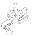
- FIG. 3 illustrates an electronic seal 30 constructed and operative in accordance with yet another preferred embodiment of the present invention.
- Electronic seal 30 is preferably similar in construction to seal 10, with like elements being designated by like numerals.
- Electronic seal 30 differs from seal 10 in that seal 30 includes an adjustment device 32 which comprises a tightening device 34 to which wire 16 is attached.
- Tightening device 34 preferably includes a conduit 36 through which wire 16 can be drawn out of and pulled into housing 12 (in the directions generally indicated by arrows 38), and a locking element 40 which selectively lockingly engages wire 16 so as to substantially fix wire 16 at a second point 42 thereof.
- Locking element 40 is preferably in electrical communication with alarm circuitry 14 and comprises a solenoid 49 which clamps down on wire 16, for example.
- Locking element 40 is also preferably in electrical communication with wire 16, so that any attempt to disconnect or detach wire 16 from locking element 40 will be sensed by alarm circuitry 14.
- wire 16 is preferably, but not necessarily, an unshielded resistive wire whose resistance can be measured from the outside, such as a conductive elastomer, e.g., an elastomeric RF gasket material.
- a portion of wire 16 can be used to form part of a Wheatstone bridge 37, in electrical communication with alarm circuitry 14, for measuring changes in electrical resistance of wire 16.
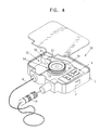
- FIG. 4 illustrates an electronic seal 50 constructed and operative in accordance with yet another preferred embodiment of the present invention.
- Electronic seal 50 is preferably similar in construction to seal 10, with like elements being designated by like numerals.
- Electronic seal 50 differs from seal 10 in that seal 50 includes an adjustment device 52 which comprises a tightening device 54 to which wire 16 is attached.
- Tightening device 54 preferably includes a bobbin 56 around which wire 16 is wound and a locking element 58, preferably a solenoid 61, which selectively lockingly engages bobbin 56.
- Bobbin 56 may include a gear, in which case solenoid 61 preferably includes a tongue 63 which engages the teeth of the gear so as to substantially fix wire 16 at a second point 59 thereof.
- locking element 58 may be manually or automatically locked and unlocked, as well as by remote control.
- the angular position and/or rotation of bobbin 56 is measured by a measuring device 60, such as an encoder.
- the initial angular position of bobbin 56 i.e., after sealing the object with seal 50, is fed to the alarm circuitry 14. Any angular change in the position of bobbin 56 is then used as a criterion for detection of tampering.
- the alarm will be indicative of an actual attempt to break into the sack only if the part of the wire that is wrapped around and actually sealing the sack is tampered with.
- tampering with the dangling part is not necessarily indicative of an attempt to pilfer or tamper with the contents of the sack, and thus would constitute a false alarm.
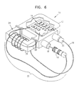
- FIG. 6 illustrates an electronic seal 10' constructed and operative in accordance with a preferred embodiment of the present invention, and which is particularly useful as a seal for tying and securing a sack and the like.
- Electronic seal 10' is preferably similar in construction to seal 10, with like elements being designated by like numerals.
- a tying portion 22 of wire 16 is defined between first and second points 18 and 20 which is suitable for tying an object, such as a sack or hasp, for example. Tampering with any portion of wire 16 actuates alarm circuitry 14, as described hereinabove.
- an adjustment device 24 is provided for adjusting a length of tying portion 22.
- adjustment device 24 comprises a yoke 26 for wrapping therearound tying portion 22.
- a user ties an object with wire 16, jack 19 being the free end of wire 16 during tying, and wraps any extra wire around yoke 26.
- jack 19 is fixedly connected to housing 12 at first point 18, and seal 10 is ready for monitoring any tampering with the object.
- An electrical element 28, such as an electrically resistive element or a conductive wire is disposed through yoke 26, electrical element 28 being in electrical communication with alarm circuitry 14. Tampering with yoke 26, or with the windings of wire 16 therearound, causes a change in electrical resistance, capacitance or any other electrical parameter, of electrical element 28, which change is communicated to alarm circuitry 14 for actuation thereof.
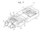
- Fig. 7 illustrates an alternative version of seal 10' wherein yoke 26 is replaced by an extender yoke 89.
- first and second points 18 and 20 are electrical connectors mounted on an external surface of extender yoke 89.
- electrical element 28 is routed through the entire inner structure of extender yoke 89.
- the embodiment of Fig. 7 operates identically to the embodiment of Fig. 6.
- Figs. I and 2 if provided with a sufficient length of wire 16 between first and second points 18 and 20, can be used to tie and secure sacks and the like, although these embodiments lack an adjustment device.
- Figs. 3 and 4 can readily be use to tie and secure sacks and the like, wherein the adjustment device 32 and 52 are provided which comprise tightening devices 34 and 54, respectively, as described hereinabove.
Landscapes
- Engineering & Computer Science (AREA)
- Computer Security & Cryptography (AREA)
- Physics & Mathematics (AREA)
- General Physics & Mathematics (AREA)
- Theoretical Computer Science (AREA)
- Burglar Alarm Systems (AREA)
- Materials For Medical Uses (AREA)
- Medical Preparation Storing Or Oral Administration Devices (AREA)
- Dental Preparations (AREA)
- Seal Device For Vehicle (AREA)
- External Artificial Organs (AREA)
Abstract
Description
Claims (23)
- An electronic seal (10) comprising:characterized by a locking element (11, 40, 58) which selectively lockingly engages said wire (16) to said housing (12); anda housing (12);alarm circuitry (14) which when actuated provides an alarm signal; anda wire (16) extending from said housing (12) and in electrical communication with said alarm circuitry (14);
a switch (15, 27) external to said housing (12) in electrical communication with said locking element (11, 40, 58) which selectively unlocks said locking element (11, 40, 58) to release said wire (16). - The electronic seal (10) according to claim 1, further characterized in that said alarm circuitry (14) detects an open circuit in a circuit comprising said alarm circuitry (14) and at least one of said wire (16) and said locking element (11, 40, 58).
- The electronic seal (10) according to claim 1, further characterized in that said switch (15, 27) is mounted on an external surface of said housing (12).
- The electronic seal (10) according to claim 3, further characterized in that said switch (15) comprises a coded switch.
- The electronic seal (10) according to claim 1, further characterized in that said switch (27) comprises a remote control device (29).
- The electronic seal (10) according to claim 5, further characterized in that said remote control device (29) communicates with said seal by means of encrypted communication.
- The method according to claim 6, further characterized in that said encrypted communication comprises a mutual zero-knowledge interaction authentication session.
- The electronic seal (10) according to claim 5, further characterized in that said remote control device (29) comprises a computer terminal (41) in wireless communication with said housing (12).
- The electronic seal (10) according to claim 1, further characterized in that said locking element (11, 40, 58) comprises a solenoid (17, 49, 61) which selectively lockingly engages said wire (16).
- The electronic seal (10) according to claim 9, further characterized in that said solenoid (17) comprises a tongue (33) which selectively protrudes from said solenoid (17) and fixedly clamps said wire (16).
- The electronic seal (10) according to claim 9, further characterized in that said wire (16) is connected to an electrical jack (19) and said solenoid (17) comprises a tongue (33) which selectively protrudes from said solenoid (17) and fixedly clamps said jack (19).
- The electronic seal (10) according to claim 9, further characterized in that said wire (16) is wound around a bobbin (56) and said solenoid (61) selectively fixedly clamps said bobbin (56), thereby also clamping said wire (16).
- The electronic seal (10) according to claim 1, further characterized in that said locking element (11, 40, 58) is selected from the group consisting of an electric motor, a piezoelectric crystal actuator, a pneumatic actuator, a hydraulic actuator, and a spring-actuated actuator.
- The electronic seal (10) according to claim 1, further characterized in that said wire (16) which extends from said housing (12) is attached at a first point (18) and at a second point (20) thereof to said housing (12), and a portion of said wire (16) between said first (18) and second (20) points, called a tying portion (22), is suitable for tying an object, wherein tampering with said wire (16) actuates said alarm circuitry (14), and the seal further comprises an adjustment device (32) for adjusting a length of said tying portion (22).
- An electronic seal (10) comprising:
a housing (12) comprising alarm circuitry (14), said alarm circuitry (14) when actuated providing an alarm signal;
characterized by a wire (16) extending from said housing (12) and in electrical communication with said alarm circuitry (14), said wire (16) being attached at a first point (18) and at a second point (20) thereof to said housing (12), a portion of said wire (16) between said first (18) and second (20) points, called a tying portion (22), being suitable for tying an object, wherein tampering with said wire (16) actuates said alarm circuitry (14); and
an adjustment device (32) for adjusting a length of said tying portion (22). - The electronic seal (10) according to claim 15, further characterized in that said adjustment device (32) comprises a yoke (26) for wrapping therearound said tying portion (22).
- The electronic seal (10) according to claim 16, further characterized in that an electrical element (28) is disposed through said yoke (26), said electrical element (28) being in electrical communication with said alarm circuitry (14), wherein a change in an electrical parameter of said electrical element (28) is communicated to said alarm circuitry (14) for actuation thereof.
- The electronic seal (10) according to claim 15, further characterized in that said adjustment device (32) comprises a tightening device (34) to which said wire (16) is attached, said tightening device (34) permitting said wire (16) to be drawn out of and to be pulled into said housing (12), and substantially fixing said wire (16) at said second point (20) thereof.
- The electronic seal (10) according to claim 18, further characterized in that said tightening device (34) comprises a locking element (11, 40, 58) which selectively lockingly engages said wire (16).
- The electronic seal (10) according to claim 18, further characterized in that said tightening device (34) comprises a bobbin (56) around which said wire (16) is wound and a locking element (11, 40, 58) which selectively lockingly engages said bobbin (56).
- The electronic seal (10) according to claim 18, and further comprising a measuring device (60) that measures a change in angular position of said bobbin (56), said measuring device (60) using said change to actuate said alarm circuitry (14).
- The electronic seal (10) according to claim 15, further characterized in that a portion of said wire (16) forms part of a Wheatstone bridge (37) in electrical communication with said alarm circuitry (14) for measuring changes in electrical resistance of said wire (16).
- The electronic seal (10) according to claim 15, further characterized in that said first point (18) is attached to an electrical connector (19) in electrical communication with said alarm circuitry (14).
Applications Claiming Priority (4)
| Application Number | Priority Date | Filing Date | Title |
|---|---|---|---|
| IL12564498A IL125644A (en) | 1998-08-03 | 1998-08-03 | Electronic sack seal |
| IL12564498 | 1998-08-03 | ||
| IL12692898 | 1998-11-05 | ||
| IL12692898A IL126928A0 (en) | 1998-11-05 | 1998-11-05 | Self-locking seal |
Publications (3)
| Publication Number | Publication Date |
|---|---|
| EP0978812A2 true EP0978812A2 (en) | 2000-02-09 |
| EP0978812A3 EP0978812A3 (en) | 2000-08-16 |
| EP0978812B1 EP0978812B1 (en) | 2006-04-12 |
Family
ID=26323688
Family Applications (1)
| Application Number | Title | Priority Date | Filing Date |
|---|---|---|---|
| EP99202520A Expired - Lifetime EP0978812B1 (en) | 1998-08-03 | 1999-08-02 | Self-locking seal |
Country Status (5)
| Country | Link |
|---|---|
| US (1) | US6243005B1 (en) |
| EP (1) | EP0978812B1 (en) |
| AT (1) | ATE323313T1 (en) |
| DE (1) | DE69930794T2 (en) |
| ES (1) | ES2264819T3 (en) |
Cited By (14)
| Publication number | Priority date | Publication date | Assignee | Title |
|---|---|---|---|---|
| GB2368174A (en) * | 2000-10-19 | 2002-04-24 | Encrypta Electronics Ltd | Security seal device with detatchable cable display indicating reopening |
| FR2816434A1 (en) * | 2000-11-06 | 2002-05-10 | Robert Stephan Touzet | Seal using an electronic chip for transport vehicles or containers, uses chip with memory which records shipping data and opening of the seal, and also stores a digital signature |
| WO2006066555A1 (en) * | 2004-12-23 | 2006-06-29 | Smartrac Ip B.V. | Sealing device |
| WO2008009148A1 (en) * | 2006-07-19 | 2008-01-24 | Pataco Ag Industrie- Und Unterhaltungstechnik | Securing device |
| EP1955297A4 (en) * | 2005-11-29 | 2009-02-25 | Checkpoint Systems Inc | Security device with perimeter alarm |
| EP1563471A4 (en) * | 2002-11-22 | 2010-06-02 | Sensormatic Electronics Corp | Proximity detaching for electronic article surveillance tags |
| CN102061841B (en) * | 2009-11-17 | 2013-01-02 | 玺瑞股份有限公司 | Electronic seal |
| WO2016055446A1 (en) * | 2014-10-08 | 2016-04-14 | Alexander Schneider | Seal for securing goods |
| DE102016120561A1 (en) * | 2016-10-27 | 2018-05-03 | Dominic Dinser | security tag |
| US10145146B2 (en) | 2012-03-19 | 2018-12-04 | Neology, Inc. | Tamper evident cargo container seal bolt lock |
| CN110570751A (en) * | 2019-07-30 | 2019-12-13 | 黄建伟 | Lead-sealed electronic tag capable of preventing shell from being replaced illegally |
| WO2020192914A1 (en) * | 2019-03-27 | 2020-10-01 | Stoba Ag | Closure element that can be monitored and seal having a closure element of this type |
| US10815694B2 (en) | 2012-03-09 | 2020-10-27 | Neology, Inc. | Tamper evident cargo container seal bolt lock |
| WO2021234288A1 (en) * | 2020-05-20 | 2021-11-25 | Ioseal | Security device for monitoring a closure system |
Families Citing this family (50)
| Publication number | Priority date | Publication date | Assignee | Title |
|---|---|---|---|---|
| US6765484B2 (en) | 2000-09-07 | 2004-07-20 | Savi Technology, Inc. | Method and apparatus for supplying commands to a tag |
| US6940392B2 (en) * | 2001-04-24 | 2005-09-06 | Savi Technology, Inc. | Method and apparatus for varying signals transmitted by a tag |
| JP3831629B2 (en) * | 2001-05-16 | 2006-10-11 | 三洋電機株式会社 | Tag device |
| US6747558B1 (en) * | 2001-11-09 | 2004-06-08 | Savi Technology, Inc. | Method and apparatus for providing container security with a tag |
| US6690267B2 (en) * | 2002-05-22 | 2004-02-10 | Edward A. Linden | Remotely controllable bicycle lock and alarm system |
| US6778083B2 (en) * | 2002-08-27 | 2004-08-17 | Hi-G-Tek Ltd. | Electronic locking seal |
| US7002472B2 (en) * | 2002-09-04 | 2006-02-21 | Northrop Grumman Corporation | Smart and secure container |
| US6700488B1 (en) * | 2002-09-05 | 2004-03-02 | Se-Kure Controls, Inc. | Security system for a portable device |
| US7042354B2 (en) | 2002-12-11 | 2006-05-09 | Hi-G-Tek Ltd. | Tamper-resistant electronic seal |
| US7518521B2 (en) | 2003-10-29 | 2009-04-14 | Display Technologies, Inc. | Rotating anti-theft tag |
| US7227467B2 (en) * | 2003-10-29 | 2007-06-05 | Display Technologies, Inc. | Anti-theft tag |
| US7187283B2 (en) * | 2004-03-18 | 2007-03-06 | Se-Kure Controls, Inc. | Security system for a portable article |
| US7242280B2 (en) * | 2004-03-18 | 2007-07-10 | Se-Kure Controls, Inc. | Security system for portable articles |
| US8068027B2 (en) * | 2004-03-30 | 2011-11-29 | Hi-G-Tek Ltd. | Monitorable locking assemblies |
| US7198227B2 (en) * | 2004-06-10 | 2007-04-03 | Goodrich Corporation | Aircraft cargo locating system |
| DE102004042436A1 (en) * | 2004-08-31 | 2006-03-02 | Max Kibellus | Safety lock for protecting object in container e.g. envelope, has pin including heading section, and housing including electromagnetic locking device that interacts with pin and is codable |
| WO2006048872A2 (en) * | 2004-11-02 | 2006-05-11 | Hi-G-Tek Inc. | Remotely monitorable electronic locking device |
| US7274293B2 (en) * | 2004-11-11 | 2007-09-25 | Black & Decker Inc. | Cable lock for security system |
| US7239244B2 (en) * | 2005-04-22 | 2007-07-03 | Se-Kure Controls, Inc. | System and method for monitoring a portable article |
| SG133417A1 (en) * | 2005-12-08 | 2007-07-30 | Brooks Asia Pte Ltd | A locking seal with tamper indication and notification device |
| US20100052907A1 (en) * | 2008-02-29 | 2010-03-04 | John Alfred Shannon | Bicycle or other mobile object anti-theft alarm device |
| GB2463526A (en) * | 2008-09-17 | 2010-03-24 | Lee Fisher | Alarmed cycle lock |
| US20100141445A1 (en) * | 2008-12-08 | 2010-06-10 | Savi Networks Inc. | Multi-Mode Commissioning/Decommissioning of Tags for Managing Assets |
| US8456302B2 (en) | 2009-07-14 | 2013-06-04 | Savi Technology, Inc. | Wireless tracking and monitoring electronic seal |
| EP2454729A1 (en) * | 2009-07-14 | 2012-05-23 | Deal Magic, Inc. | Security seal |
| US8432274B2 (en) | 2009-07-31 | 2013-04-30 | Deal Magic, Inc. | Contextual based determination of accuracy of position fixes |
| SG178484A1 (en) | 2009-08-17 | 2012-04-27 | Deal Magic Inc | Contextually aware monitoring of assets |
| US8334773B2 (en) | 2009-08-28 | 2012-12-18 | Deal Magic, Inc. | Asset monitoring and tracking system |
| US8314704B2 (en) * | 2009-08-28 | 2012-11-20 | Deal Magic, Inc. | Asset tracking using alternative sources of position fix data |
| US20110050397A1 (en) * | 2009-08-28 | 2011-03-03 | Cova Nicholas D | System for generating supply chain management statistics from asset tracking data |
| US8666664B2 (en) * | 2009-11-27 | 2014-03-04 | Syris Technology Corp. | Electronic seal |
| US8065895B2 (en) * | 2010-02-26 | 2011-11-29 | Andersen Holdings, LLC | Public facility bicycle lock |
| CH703299A1 (en) * | 2010-06-07 | 2011-12-15 | Pataco Ag Ind Und Unterhaltungselektronik | Safety device for objects. |
| DE102011004940A1 (en) * | 2011-03-02 | 2012-09-06 | Deutsche Post Ag | seal system |
| US9022162B2 (en) * | 2011-06-23 | 2015-05-05 | Honda Motor Co., Ltd. | Vehicle anti-theft device |
| US8487768B2 (en) * | 2011-08-30 | 2013-07-16 | Chung-Shan Institute Of Science And Technology, Armaments Bureau, Ministry Of National Defense | Electronic seal equipped with a breakage-detecting circuit and method for sealing a door based on the same |
| EP2568443B1 (en) * | 2011-09-07 | 2016-04-20 | National Chung-Shan Institute of Science and Technology | Electronic seal equipped with a breakage-detecting circuit and method for sealing a door based on the same |
| US20140007628A1 (en) * | 2012-07-06 | 2014-01-09 | Entreprises Mobilock Inc. | Electronic locking device for securing goods |
| US20140091781A1 (en) * | 2012-09-28 | 2014-04-03 | Hutchison International Ports Enterprises Limited | Security system |
| CN103987906B (en) * | 2012-10-05 | 2016-06-29 | 极速科技私人有限公司 | Safety device |
| US9299232B2 (en) * | 2013-12-20 | 2016-03-29 | Checkpoint Systems, Inc. | Security device with dual use transformer |
| US9222285B1 (en) * | 2014-08-01 | 2015-12-29 | Perseus Micro Logic Corporation | Theft deterrent device and method of use |
| IT201600076082A1 (en) * | 2016-07-26 | 2018-01-26 | Daniele Tommei | ELASTIC RING SAFETY DEVICE FOR SEALING AND CERTIFYING THE DATA STORED IN IT |
| CN108665046B (en) * | 2018-05-29 | 2021-04-02 | 京东方科技集团股份有限公司 | Anti-disassembly monitoring circuit, electronic tag, anti-theft system and anti-theft method thereof |
| CN109147551A (en) * | 2018-06-20 | 2019-01-04 | 郴州多特科技发展有限公司 | E-seals |
| CN110094110B (en) * | 2019-05-24 | 2020-11-17 | 尹文秋 | Facing slip lock management device and method |
| US12378796B1 (en) * | 2021-11-22 | 2025-08-05 | Oliver Anthony Spittle | Electronic lock with service subscription |
| CN114575680B (en) * | 2022-04-22 | 2022-10-21 | 浙江华邦物联技术股份有限公司 | Intelligence steel wire seals based on NFC |
| US20240410201A1 (en) * | 2023-06-09 | 2024-12-12 | Two Ton Technology, Llc | Electronically releasable apparatus |
| US20250111761A1 (en) * | 2023-10-02 | 2025-04-03 | Monitainer Tecnologia E Serviços Ltda | Dual-technology electronic seal with integrity monitoring system and integrity monitoring method of said seal |
Family Cites Families (12)
| Publication number | Priority date | Publication date | Assignee | Title |
|---|---|---|---|---|
| US3913010A (en) * | 1973-07-16 | 1975-10-14 | Amax Inc | Means and method for measuring electrical-ground resistance between earth-separated locations |
| US4748668A (en) | 1986-07-09 | 1988-05-31 | Yeda Research And Development Company Limited | Method, apparatus and article for identification and signature |
| US5097253A (en) * | 1989-01-06 | 1992-03-17 | Battelle Memorial Institute | Electronic security device |
| US4920334A (en) * | 1989-04-24 | 1990-04-24 | Devolpi Dean R | Security system for bicycles, ski racks and coat racks |
| US5270681A (en) * | 1991-10-21 | 1993-12-14 | Jack Lynn E | Bicycle and bicycle elements theft alarm apparatus |
| US5408212A (en) * | 1992-09-18 | 1995-04-18 | Brio Corporation | Multi-mode combination alarm and locking apparatus for bicycles, motorcycles and the like |
| US5408213A (en) * | 1993-05-12 | 1995-04-18 | Ungarsohn; Benjamin I. | Portable breakaway alarm system |
| US5917405A (en) * | 1993-06-08 | 1999-06-29 | Joao; Raymond Anthony | Control apparatus and methods for vehicles |
| US5767773A (en) * | 1994-07-29 | 1998-06-16 | Kubota Corporation | Theft preventive apparatus and radio wave receiving signaling device |
| US5836002A (en) * | 1995-06-01 | 1998-11-10 | Morstein; Jason | Anti-theft device |
| US5749533A (en) * | 1995-08-03 | 1998-05-12 | Daniels; John J. | Fishing reel with electronically variable brake for preventing backlash |
| US5786759A (en) * | 1997-05-15 | 1998-07-28 | Ling; Chong-Kuan | Alarming wire lock |
-
1999
- 1999-08-02 AT AT99202520T patent/ATE323313T1/en not_active IP Right Cessation
- 1999-08-02 ES ES99202520T patent/ES2264819T3/en not_active Expired - Lifetime
- 1999-08-02 EP EP99202520A patent/EP0978812B1/en not_active Expired - Lifetime
- 1999-08-02 DE DE69930794T patent/DE69930794T2/en not_active Expired - Lifetime
- 1999-08-03 US US09/368,285 patent/US6243005B1/en not_active Expired - Lifetime
Cited By (19)
| Publication number | Priority date | Publication date | Assignee | Title |
|---|---|---|---|---|
| GB2368174A (en) * | 2000-10-19 | 2002-04-24 | Encrypta Electronics Ltd | Security seal device with detatchable cable display indicating reopening |
| FR2816434A1 (en) * | 2000-11-06 | 2002-05-10 | Robert Stephan Touzet | Seal using an electronic chip for transport vehicles or containers, uses chip with memory which records shipping data and opening of the seal, and also stores a digital signature |
| EP1563471A4 (en) * | 2002-11-22 | 2010-06-02 | Sensormatic Electronics Corp | Proximity detaching for electronic article surveillance tags |
| CN101142606B (en) * | 2004-12-23 | 2011-07-06 | 斯迈达Ip有限公司 | sealing equipment |
| WO2006066555A1 (en) * | 2004-12-23 | 2006-06-29 | Smartrac Ip B.V. | Sealing device |
| DE102004063487A1 (en) * | 2004-12-23 | 2006-07-13 | Intec Holding Gmbh | sealer |
| US7878561B2 (en) | 2004-12-23 | 2011-02-01 | Smartrac Ip B.V. | Seal device |
| EP1955297A4 (en) * | 2005-11-29 | 2009-02-25 | Checkpoint Systems Inc | Security device with perimeter alarm |
| WO2008009148A1 (en) * | 2006-07-19 | 2008-01-24 | Pataco Ag Industrie- Und Unterhaltungstechnik | Securing device |
| CN102061841B (en) * | 2009-11-17 | 2013-01-02 | 玺瑞股份有限公司 | Electronic seal |
| US10815694B2 (en) | 2012-03-09 | 2020-10-27 | Neology, Inc. | Tamper evident cargo container seal bolt lock |
| US10145146B2 (en) | 2012-03-19 | 2018-12-04 | Neology, Inc. | Tamper evident cargo container seal bolt lock |
| US10689882B2 (en) | 2012-03-19 | 2020-06-23 | Neology, Inc. | Tamper evident cargo container seal bolt lock |
| WO2016055446A1 (en) * | 2014-10-08 | 2016-04-14 | Alexander Schneider | Seal for securing goods |
| DE102016120561A1 (en) * | 2016-10-27 | 2018-05-03 | Dominic Dinser | security tag |
| WO2020192914A1 (en) * | 2019-03-27 | 2020-10-01 | Stoba Ag | Closure element that can be monitored and seal having a closure element of this type |
| CN110570751A (en) * | 2019-07-30 | 2019-12-13 | 黄建伟 | Lead-sealed electronic tag capable of preventing shell from being replaced illegally |
| WO2021234288A1 (en) * | 2020-05-20 | 2021-11-25 | Ioseal | Security device for monitoring a closure system |
| FR3110761A1 (en) * | 2020-05-20 | 2021-11-26 | Ioseal | Safety device for monitoring a locking system |
Also Published As
| Publication number | Publication date |
|---|---|
| HK1025653A1 (en) | 2000-11-17 |
| EP0978812B1 (en) | 2006-04-12 |
| ATE323313T1 (en) | 2006-04-15 |
| DE69930794D1 (en) | 2006-05-24 |
| US6243005B1 (en) | 2001-06-05 |
| EP0978812A3 (en) | 2000-08-16 |
| DE69930794T2 (en) | 2007-04-12 |
| ES2264819T3 (en) | 2007-01-16 |
Similar Documents
| Publication | Publication Date | Title |
|---|---|---|
| US6243005B1 (en) | Self-locking seal | |
| US6281793B1 (en) | Electronic monitoring apparatus | |
| US5656996A (en) | Electronic security bonding device | |
| CA2622585C (en) | Electronic tamper evident seal | |
| CN102216969B (en) | Sealing device | |
| CN1692382A (en) | Smart container monitoring system | |
| WO1997034269A9 (en) | Electronic security bonding device | |
| US20140091781A1 (en) | Security system | |
| DE60122202T2 (en) | Property transfer procedure using security reset chains | |
| HK1025653B (en) | Self-locking seal | |
| US20080291019A1 (en) | Remotely Monitorable Electronic Locking Device | |
| CN108428311B (en) | A kind of application method of metering device burglary-resisting system | |
| IL125644A (en) | Electronic sack seal | |
| EP0983917B1 (en) | Electronic filament netting | |
| KR102059343B1 (en) | How to install the sealing bolts and sealing bolts | |
| GB2280290A (en) | Commodity metering apparatus | |
| WO2013081469A1 (en) | Electronic seal device | |
| RU51735U1 (en) | ELECTRONIC LOCK-FILLING DEVICE (OPTIONS) | |
| WO2018091053A1 (en) | Electronic cable seal | |
| CN114113741B (en) | Voltage sensor based on anti-tampering function | |
| CN208765832U (en) | Weighing instrument lead seal structure and weighing instrument | |
| KR200362297Y1 (en) | A condition recognize device of packing car | |
| RU2202719C1 (en) | Cable length clamping device | |
| CN206760944U (en) | A kind of antiwithdrawal device applied to dismantling-proof alarming watch | |
| KR20110061853A (en) | Cantilever Management Box |
Legal Events
| Date | Code | Title | Description |
|---|---|---|---|
| PUAI | Public reference made under article 153(3) epc to a published international application that has entered the european phase |
Free format text: ORIGINAL CODE: 0009012 |
|
| AK | Designated contracting states |
Kind code of ref document: A2 Designated state(s): AT BE CH CY DE DK ES FI FR GB GR IE IT LI LU MC NL PT SE |
|
| AX | Request for extension of the european patent |
Free format text: AL;LT;LV;MK;RO;SI |
|
| PUAL | Search report despatched |
Free format text: ORIGINAL CODE: 0009013 |
|
| AK | Designated contracting states |
Kind code of ref document: A3 Designated state(s): AT BE CH CY DE DK ES FI FR GB GR IE IT LI LU MC NL PT SE |
|
| AX | Request for extension of the european patent |
Free format text: AL;LT;LV;MK;RO;SI |
|
| RIC1 | Information provided on ipc code assigned before grant |
Free format text: 7G 09F 3/03 A, 7E 05B 45/00 B, 7G 08B 13/14 B |
|
| 17P | Request for examination filed |
Effective date: 20010213 |
|
| AKX | Designation fees paid |
Free format text: AT BE CH CY DE DK ES FI FR GB GR IE IT LI LU MC NL PT SE |
|
| 17Q | First examination report despatched |
Effective date: 20020102 |
|
| GRAP | Despatch of communication of intention to grant a patent |
Free format text: ORIGINAL CODE: EPIDOSNIGR1 |
|
| GRAS | Grant fee paid |
Free format text: ORIGINAL CODE: EPIDOSNIGR3 |
|
| GRAA | (expected) grant |
Free format text: ORIGINAL CODE: 0009210 |
|
| AK | Designated contracting states |
Kind code of ref document: B1 Designated state(s): AT BE CH CY DE DK ES FI FR GB GR IE IT LI LU MC NL PT SE |
|
| PG25 | Lapsed in a contracting state [announced via postgrant information from national office to epo] |
Ref country code: LI Free format text: LAPSE BECAUSE OF FAILURE TO SUBMIT A TRANSLATION OF THE DESCRIPTION OR TO PAY THE FEE WITHIN THE PRESCRIBED TIME-LIMIT Effective date: 20060412 Ref country code: IT Free format text: LAPSE BECAUSE OF FAILURE TO SUBMIT A TRANSLATION OF THE DESCRIPTION OR TO PAY THE FEE WITHIN THE PRESCRIBED TIME-LIMIT;WARNING: LAPSES OF ITALIAN PATENTS WITH EFFECTIVE DATE BEFORE 2007 MAY HAVE OCCURRED AT ANY TIME BEFORE 2007. THE CORRECT EFFECTIVE DATE MAY BE DIFFERENT FROM THE ONE RECORDED. Effective date: 20060412 Ref country code: FI Free format text: LAPSE BECAUSE OF FAILURE TO SUBMIT A TRANSLATION OF THE DESCRIPTION OR TO PAY THE FEE WITHIN THE PRESCRIBED TIME-LIMIT Effective date: 20060412 Ref country code: CH Free format text: LAPSE BECAUSE OF FAILURE TO SUBMIT A TRANSLATION OF THE DESCRIPTION OR TO PAY THE FEE WITHIN THE PRESCRIBED TIME-LIMIT Effective date: 20060412 Ref country code: BE Free format text: LAPSE BECAUSE OF FAILURE TO SUBMIT A TRANSLATION OF THE DESCRIPTION OR TO PAY THE FEE WITHIN THE PRESCRIBED TIME-LIMIT Effective date: 20060412 Ref country code: AT Free format text: LAPSE BECAUSE OF FAILURE TO SUBMIT A TRANSLATION OF THE DESCRIPTION OR TO PAY THE FEE WITHIN THE PRESCRIBED TIME-LIMIT Effective date: 20060412 |
|
| REG | Reference to a national code |
Ref country code: GB Ref legal event code: FG4D |
|
| REG | Reference to a national code |
Ref country code: CH Ref legal event code: EP |
|
| REF | Corresponds to: |
Ref document number: 69930794 Country of ref document: DE Date of ref document: 20060524 Kind code of ref document: P |
|
| REG | Reference to a national code |
Ref country code: IE Ref legal event code: FG4D |
|
| PG25 | Lapsed in a contracting state [announced via postgrant information from national office to epo] |
Ref country code: SE Free format text: LAPSE BECAUSE OF FAILURE TO SUBMIT A TRANSLATION OF THE DESCRIPTION OR TO PAY THE FEE WITHIN THE PRESCRIBED TIME-LIMIT Effective date: 20060712 Ref country code: DK Free format text: LAPSE BECAUSE OF FAILURE TO SUBMIT A TRANSLATION OF THE DESCRIPTION OR TO PAY THE FEE WITHIN THE PRESCRIBED TIME-LIMIT Effective date: 20060712 |
|
| PG25 | Lapsed in a contracting state [announced via postgrant information from national office to epo] |
Ref country code: IE Free format text: LAPSE BECAUSE OF NON-PAYMENT OF DUE FEES Effective date: 20060802 |
|
| PG25 | Lapsed in a contracting state [announced via postgrant information from national office to epo] |
Ref country code: MC Free format text: LAPSE BECAUSE OF NON-PAYMENT OF DUE FEES Effective date: 20060831 |
|
| PG25 | Lapsed in a contracting state [announced via postgrant information from national office to epo] |
Ref country code: PT Free format text: LAPSE BECAUSE OF FAILURE TO SUBMIT A TRANSLATION OF THE DESCRIPTION OR TO PAY THE FEE WITHIN THE PRESCRIBED TIME-LIMIT Effective date: 20060912 |
|
| REG | Reference to a national code |
Ref country code: CH Ref legal event code: PL |
|
| REG | Reference to a national code |
Ref country code: HK Ref legal event code: GR Ref document number: 1025653 Country of ref document: HK |
|
| ET | Fr: translation filed | ||
| REG | Reference to a national code |
Ref country code: ES Ref legal event code: FG2A Ref document number: 2264819 Country of ref document: ES Kind code of ref document: T3 |
|
| PLBE | No opposition filed within time limit |
Free format text: ORIGINAL CODE: 0009261 |
|
| STAA | Information on the status of an ep patent application or granted ep patent |
Free format text: STATUS: NO OPPOSITION FILED WITHIN TIME LIMIT |
|
| 26N | No opposition filed |
Effective date: 20070115 |
|
| PG25 | Lapsed in a contracting state [announced via postgrant information from national office to epo] |
Ref country code: GR Free format text: LAPSE BECAUSE OF FAILURE TO SUBMIT A TRANSLATION OF THE DESCRIPTION OR TO PAY THE FEE WITHIN THE PRESCRIBED TIME-LIMIT Effective date: 20060713 |
|
| PG25 | Lapsed in a contracting state [announced via postgrant information from national office to epo] |
Ref country code: LU Free format text: LAPSE BECAUSE OF NON-PAYMENT OF DUE FEES Effective date: 20060802 |
|
| REG | Reference to a national code |
Ref country code: GB Ref legal event code: 732E |
|
| PG25 | Lapsed in a contracting state [announced via postgrant information from national office to epo] |
Ref country code: CY Free format text: LAPSE BECAUSE OF FAILURE TO SUBMIT A TRANSLATION OF THE DESCRIPTION OR TO PAY THE FEE WITHIN THE PRESCRIBED TIME-LIMIT Effective date: 20060412 |
|
| PGFP | Annual fee paid to national office [announced via postgrant information from national office to epo] |
Ref country code: ES Payment date: 20090821 Year of fee payment: 11 |
|
| PGFP | Annual fee paid to national office [announced via postgrant information from national office to epo] |
Ref country code: NL Payment date: 20090814 Year of fee payment: 11 Ref country code: GB Payment date: 20090827 Year of fee payment: 11 Ref country code: DE Payment date: 20090821 Year of fee payment: 11 |
|
| REG | Reference to a national code |
Ref country code: NL Ref legal event code: V1 Effective date: 20110301 |
|
| GBPC | Gb: european patent ceased through non-payment of renewal fee |
Effective date: 20100802 |
|
| REG | Reference to a national code |
Ref country code: FR Ref legal event code: ST Effective date: 20110502 |
|
| PG25 | Lapsed in a contracting state [announced via postgrant information from national office to epo] |
Ref country code: NL Free format text: LAPSE BECAUSE OF NON-PAYMENT OF DUE FEES Effective date: 20110301 |
|
| REG | Reference to a national code |
Ref country code: DE Ref legal event code: R119 Ref document number: 69930794 Country of ref document: DE Effective date: 20110301 |
|
| PG25 | Lapsed in a contracting state [announced via postgrant information from national office to epo] |
Ref country code: FR Free format text: LAPSE BECAUSE OF NON-PAYMENT OF DUE FEES Effective date: 20100831 Ref country code: DE Free format text: LAPSE BECAUSE OF NON-PAYMENT OF DUE FEES Effective date: 20110301 |
|
| PG25 | Lapsed in a contracting state [announced via postgrant information from national office to epo] |
Ref country code: GB Free format text: LAPSE BECAUSE OF NON-PAYMENT OF DUE FEES Effective date: 20100802 |
|
| PGFP | Annual fee paid to national office [announced via postgrant information from national office to epo] |
Ref country code: FR Payment date: 20090914 Year of fee payment: 11 |
|
| REG | Reference to a national code |
Ref country code: ES Ref legal event code: FD2A Effective date: 20111020 |
|
| PG25 | Lapsed in a contracting state [announced via postgrant information from national office to epo] |
Ref country code: ES Free format text: LAPSE BECAUSE OF NON-PAYMENT OF DUE FEES Effective date: 20100803 |