EP0978631A1 - Dampfgetriebene antriebsmaschine - Google Patents
Dampfgetriebene antriebsmaschine Download PDFInfo
- Publication number
- EP0978631A1 EP0978631A1 EP97918441A EP97918441A EP0978631A1 EP 0978631 A1 EP0978631 A1 EP 0978631A1 EP 97918441 A EP97918441 A EP 97918441A EP 97918441 A EP97918441 A EP 97918441A EP 0978631 A1 EP0978631 A1 EP 0978631A1
- Authority
- EP
- European Patent Office
- Prior art keywords
- steam
- oil
- vending
- screws
- shaft
- Prior art date
- Legal status (The legal status is an assumption and is not a legal conclusion. Google has not performed a legal analysis and makes no representation as to the accuracy of the status listed.)
- Withdrawn
Links
- 238000011067 equilibration Methods 0.000 claims abstract description 9
- 230000005540 biological transmission Effects 0.000 claims description 19
- 230000003993 interaction Effects 0.000 claims description 5
- 238000006243 chemical reaction Methods 0.000 claims description 4
- 230000000712 assembly Effects 0.000 abstract 2
- 238000000429 assembly Methods 0.000 abstract 2
- 239000003921 oil Substances 0.000 description 39
- 230000035515 penetration Effects 0.000 description 4
- 238000002955 isolation Methods 0.000 description 3
- 238000009833 condensation Methods 0.000 description 2
- 230000005494 condensation Effects 0.000 description 2
- 230000009466 transformation Effects 0.000 description 2
- 239000003638 chemical reducing agent Substances 0.000 description 1
- 238000006073 displacement reaction Methods 0.000 description 1
- 230000000694 effects Effects 0.000 description 1
- 238000009434 installation Methods 0.000 description 1
- 239000007788 liquid Substances 0.000 description 1
- 238000011089 mechanical engineering Methods 0.000 description 1
- 230000001737 promoting effect Effects 0.000 description 1
- 238000007789 sealing Methods 0.000 description 1
- 239000007787 solid Substances 0.000 description 1
- 230000007306 turnover Effects 0.000 description 1
- XLYOFNOQVPJJNP-UHFFFAOYSA-N water Substances O XLYOFNOQVPJJNP-UHFFFAOYSA-N 0.000 description 1
Images


Classifications
-
- F—MECHANICAL ENGINEERING; LIGHTING; HEATING; WEAPONS; BLASTING
- F16—ENGINEERING ELEMENTS AND UNITS; GENERAL MEASURES FOR PRODUCING AND MAINTAINING EFFECTIVE FUNCTIONING OF MACHINES OR INSTALLATIONS; THERMAL INSULATION IN GENERAL
- F16J—PISTONS; CYLINDERS; SEALINGS
- F16J15/00—Sealings
- F16J15/44—Free-space packings
- F16J15/441—Free-space packings with floating ring
-
- F—MECHANICAL ENGINEERING; LIGHTING; HEATING; WEAPONS; BLASTING
- F04—POSITIVE - DISPLACEMENT MACHINES FOR LIQUIDS; PUMPS FOR LIQUIDS OR ELASTIC FLUIDS
- F04C—ROTARY-PISTON, OR OSCILLATING-PISTON, POSITIVE-DISPLACEMENT MACHINES FOR LIQUIDS; ROTARY-PISTON, OR OSCILLATING-PISTON, POSITIVE-DISPLACEMENT PUMPS
- F04C27/00—Sealing arrangements in rotary-piston pumps specially adapted for elastic fluids
- F04C27/008—Sealing arrangements in rotary-piston pumps specially adapted for elastic fluids for other than working fluid, i.e. the sealing arrangements are not between working chambers of the machine
- F04C27/009—Shaft sealings specially adapted for pumps
Definitions
- the invention concerns to field of a mechanical engineering, in particular to steam extension machines of unvolumetric displacement, namely to steam-driven propeller engines intended for transformation of steam energy into mechanical energy.
- the steam-driven propeller engine (SU, 1146482), comprising tank, with drive and driven screws in a linkage placed in it, shafts of which are placed in bearing nodes, output and synchronizing transmissions, by means of the first of which drive screw is connected to the output shaft, and by means of the second - drive and driven screws are connected among themselves, inlet and outlet branch pipes for feed and vending of a working body, in particular steam, cylinder for compensation of axial gains, sliding detail of which is connected to the shaft of the drive screw, and greasing system of bearing nodes and mentioned transmissions, thus output and synchronizing transmissions are located on the different sides from the mentioned screws, and inlet branch pipe and cylinder are connected with a source a steam.
- the task put in a basis of the present invention is to create the steam-driven propeller engine possessing increased efficiency while increasing of its a motor-resource by improving of seals of operation and technological clearances between sliding and motionless details of the steam-driven propeller engine, including clearances between screws and of more effective utilization of a working body, and also by the equilibration of forces operating on solid of revolution, including in bearing nodes.
- the set task is solved by that the known steam-driven propeller engine comprising tank, with drive and driven screws in a linkage placed in it, shafts of which are placed in bearing nodes, output and synchronizing transmissions, by means of the first of which drive screw is connected to the output shaft, and by means of the second - drive and driven screws are connected among themselves, inlet and outlet branch pipes for feed and vending of a working body, in particular steam, cylinder for compensation of axial gains, sliding detail of which is connected to the shaft of the drive screw, and greasing system of bearing nodes and mentioned transmissions, thus output and synchronizing transmissions are located on the different sides from the mentioned screws, and inlet branch pipe and cylinder are connected with a source a steam, it is supplied with the device for an equilibration of jet gains in bearing nodes originating on the part of screws, both separators a steam and oil placed on shafts between screws and bearing nodes, thus the device for an equilibration of jet gains in bearing nodes is executed as a space formed between the shaft
- each separator of steam and oil is made in the form of seal rings, between which the units of a vending of steam and / or oil are located.
- each unit of a vending of steam and / or oil is made in the form of, at least, two spaces, each of which is located between conversion to each other seal rings, and the first space - a drainage one, is located on the side of a bearing node, is connected by the channel with the atmosphere, and the second space is located on the side of the screw, is connected by means of the channel with the outlet branch pipe.
- the unit of vending of the steam and / or oil is supplied by the mechanism of a forced vending of steam and oil.
- the mechanism of a forced vending of steam and / or oil is made in the form of the diaphragm, located between conversion to each other seal rings with clearances, one of which from the side of a bearing node is connected with the channel connected to a hydraulic reservoir of the system of greasing, and the second clearance located on the side of the screw, is connected with the channel connected to an atmosphere, thus on a surface of the shaft or the diaphragm on a site of their interaction the opposite directed screw, which inputs are connected with an atmosphere, and outputs with an appropriate clearance, thus the screw groove connected with a clearance, which is connected with a hydraulic reservoir, is executed with a direction appropriate to a direction of the drive screw, with the possibility of a support of a forced vending of the penetrated oil in a hydraulic reservoir.
- the steam-driven propeller engine according to the invention comprises tank 1 (fig. 1), in the camera of high pressure of which the drive 2 and driven 3 screws in a linkage, the shafts 4 and 5 of which are placed in the bearing nodes 6 are located.
- the screws are connected among themselves by synchronizing transmission 7, gears of which are placed on shafts 4 and 5 on the one side of screws.
- the output transmission 8 intended for removal of output power and connected on the one side with the drive screw 2, and on the other side - with the output shaft 9 of the machine is located.
- the inlet and outlet branch pipes 10 and 11 are made for feed and vending the steam, the first one is connected with the camera of high pressure and with the source of the steam ensuring feed of the heat-carrier under high pressure in the said camera (represented as an arrow and solid line).
- the system of greasing of bearing nodes 6 and transmissions 7 and 8 is made in the form of the pump 12 (fig. 1) with a drive from the output shalt 9.
- the input of the pump 12 is hydraulically connected to a hydraulic reservoir 13, and the output of the pump 12 through the cooler 14 of oil and filter 15 - with a forcing oil collector 16, ensuring feed of oil in a zone of transmissions 7 and 8, and also to the bearing node 6 (represented as an arrow and dashed line).
- the steam-driven propeller engine (fig. 1) is supplied with the cylinder 17 for compensation of axial gains, the piston 18 of which is connected to the shaft 4 of the drive screw 2, thus the space of the cylinder 17 is connected with a source of the steam.
- each separator of steam and oil is made in the form of placed in some numbers seal rings 19, some of which are conversed to each other with the possibility of preventing of a penetration of steam or oil from the opposite directions.
- seal rings 19 conversed to each other, the units of vending the steam and / or oil are located.
- the unit of vending the steam and / or oil is made in the form of, at least, two spaces 20 and 21 (fig.3,4), each of which is located between the seal rings 19, and the first 20, located on the side of a bearing node, is connected by the channel 22 with the atmosphere - executes the function of a drainage space, and the second space 21, located on the side of the appropriate screw, is connected by means of the channel 23 with the outlet branch pipe.
- two spaces 20 and 21 (fig.3,4), each of which is located between the seal rings 19, and the first 20, located on the side of a bearing node, is connected by the channel 22 with the atmosphere - executes the function of a drainage space, and the second space 21, located on the side of the appropriate screw, is connected by means of the channel 23 with the outlet branch pipe.
- the mechanism of a forced vending of steam and / or oil is made in the form of the diaphragm 24 (fig.4), located between conversed to each other seal rings 19 with clearances 25, one of which from the side of the bearing node 6 is connected with the channel 26 of a hydraulic reservoir 13 of greasing system, and the second clearance located on the side of the screw, is connected with the channel 23, connected with the outlet branch pipe 11.
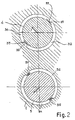
- the device for an equilibration of jet gains in the bearing nodes also is intended for reaching of this effect.
- the device (fig.2) is located on shaft 4 and 5 between screws 2 and 3 and the bearing nodes 6.
- Each device is made in the form of a space 32, formed between the shaft 4 or 5 and tank 1 and connected on the one side with a source of steam, and on the other side - by means of, at least one throttling channel 33 with the outlet branch pipe 11, in particular through the intermediate camera 34.
- the variant of execution of the throttling channel 33 in the form of a slot formed between the shaft of the screw and a hanging indent 35 of tank 1 is represented.
- throttling channels 33 are made in the form of the holes 36, placed in hanging indents 35.
- the hanging indents 35 are made on tank 1 along the shaft 4 and 5 of the appropriate screw 2 and 3 and divide a space 32 and intermediate camera 34 among themselves.
- the space 32 is made in tank 1 and is placed along a lateral area of the shaft 4 or 5 on a site located opposite to a direction of operation of jet gains.
- the seal ring 19 (fig.3,4) is made in the form of a barrel 37 with placed in it and spring-loaded concerning it seal unit executed with a casing 38.
- the seal rings 19, located on shafts 4 and 5, are placed in the intermediate tank 39.
- the steam under high pressure comes in an inlet branch pipe 10 and reduces in rotation screws 2 and 3 (fig. 1,3 and 4). Completed of steam comes out through the outlet branch pipe 11 under pressure exceeding the atmospheric one. At the same time the steam from its source under high pressure comes into the cylinder 17, where exposing on the piston 18, connected with the shaft 4, forms the force opposite to axial gains, stipulated, in particular by interaction of screws 2 and 3 among themselves and with the heat-carrier. During the transformation of energy of the heat-carrier in mechanical energy the steam under high pressure constantly moves in a space 32 (fig.2) of the device for an equilibration of jet gains in the bearing nodes 6.
- the pump 12 gives oil under pressure through a filter 15 and cooler 14 to transmissions 7 and 8, and also in the bearing nodes 6.
- the present invention can be used in power installations, ground and water vehicles.
Landscapes
- Engineering & Computer Science (AREA)
- General Engineering & Computer Science (AREA)
- Mechanical Engineering (AREA)
- Engine Equipment That Uses Special Cycles (AREA)
- Exposure And Positioning Against Photoresist Photosensitive Materials (AREA)
Applications Claiming Priority (1)
| Application Number | Priority Date | Filing Date | Title |
|---|---|---|---|
| PCT/RU1997/000087 WO1998042951A1 (fr) | 1997-03-26 | 1997-03-26 | Machine a vapeur a vis |
Publications (2)
| Publication Number | Publication Date |
|---|---|
| EP0978631A1 true EP0978631A1 (de) | 2000-02-09 |
| EP0978631A4 EP0978631A4 (de) | 2004-03-17 |
Family
ID=20130096
Family Applications (1)
| Application Number | Title | Priority Date | Filing Date |
|---|---|---|---|
| EP97918441A Withdrawn EP0978631A4 (de) | 1997-03-26 | 1997-03-26 | Dampfgetriebene antriebsmaschine |
Country Status (5)
| Country | Link |
|---|---|
| US (1) | US6283739B1 (de) |
| EP (1) | EP0978631A4 (de) |
| AU (1) | AU2654497A (de) |
| UA (1) | UA43456C2 (de) |
| WO (1) | WO1998042951A1 (de) |
Families Citing this family (2)
| Publication number | Priority date | Publication date | Assignee | Title |
|---|---|---|---|---|
| JP4578780B2 (ja) * | 2003-03-03 | 2010-11-10 | 財団法人国際科学振興財団 | 真空ポンプ |
| JP7189749B2 (ja) * | 2018-12-04 | 2022-12-14 | 株式会社日立産機システム | スクリュー圧縮機 |
Family Cites Families (12)
| Publication number | Priority date | Publication date | Assignee | Title |
|---|---|---|---|---|
| US598906A (en) * | 1898-02-15 | Rotary steam-engine | ||
| SE218587C1 (de) * | 1961-11-08 | 1968-01-30 | ||
| GB1570512A (en) * | 1976-09-04 | 1980-07-02 | Howden Compressors Ltd | Meshing-screw gas-compressing apparatus |
| JPS5468510A (en) * | 1977-11-11 | 1979-06-01 | Kobe Steel Ltd | Gas leak preventive method for self-lubricating screw compressor |
| JPS5951190A (ja) * | 1982-09-17 | 1984-03-24 | Hitachi Ltd | オイルフリ−スクリユ−圧縮機の油切り装置 |
| JPH0696978B2 (ja) * | 1985-12-03 | 1994-11-30 | トヨタ自動車株式会社 | 過給機付内燃機関 |
| JPS6429690A (en) * | 1987-07-22 | 1989-01-31 | Hitachi Ltd | Shaft sealing device for screw vacuum pump |
| US4781553A (en) | 1987-07-24 | 1988-11-01 | Kabushiki Kaisha Kobe Seiko Sho | Screw vacuum pump with lubricated bearings and a plurality of shaft sealing means |
| JP2515831B2 (ja) * | 1987-12-18 | 1996-07-10 | 株式会社日立製作所 | スクリユ―真空ポンプ |
| US5228298A (en) | 1992-04-16 | 1993-07-20 | Praxair Technology, Inc. | Cryogenic rectification system with helical dry screw expander |
| SE500488C2 (sv) * | 1993-05-14 | 1994-07-04 | Svenska Rotor Maskiner Ab | Skruvkompressor med tätningsorgan |
| RU2076246C1 (ru) * | 1994-02-18 | 1997-03-27 | Товарищество с ограниченной ответственностью "ЭКМОТО" | Пароводяной детандер |
-
1997
- 1997-03-26 AU AU26544/97A patent/AU2654497A/en not_active Abandoned
- 1997-03-26 WO PCT/RU1997/000087 patent/WO1998042951A1/ru not_active Ceased
- 1997-03-26 EP EP97918441A patent/EP0978631A4/de not_active Withdrawn
- 1997-03-26 US US09/402,044 patent/US6283739B1/en not_active Expired - Fee Related
- 1997-03-26 UA UA99084766A patent/UA43456C2/uk unknown
Also Published As
| Publication number | Publication date |
|---|---|
| AU2654497A (en) | 1998-10-20 |
| EP0978631A4 (de) | 2004-03-17 |
| UA43456C2 (uk) | 2001-12-17 |
| US6283739B1 (en) | 2001-09-04 |
| WO1998042951A1 (fr) | 1998-10-01 |
Similar Documents
| Publication | Publication Date | Title |
|---|---|---|
| RU2310106C2 (ru) | Уплотненный подшипник качения с масляным демпфированием | |
| US4153395A (en) | Compressors | |
| US3525215A (en) | Counter piston machine,preferably counter piston motor with hydraulic driving mechanism | |
| EP1731735A3 (de) | Mehrwellen-Gasturbine mit einem hydraulischen Lastverteilungssystem. | |
| ES2019411B3 (es) | Valvula motriz con transmision hidraulica y caracteristicas variables mediante manivelas de control. | |
| GB2102093A (en) | Preventing ingress of clutch actuating oil into change speed gear | |
| JP4485729B2 (ja) | ターボマシンで軸方向スラストを補償する装置 | |
| US8627746B2 (en) | Transmission, particularly compressor wheel gear and methods to improve the starting behavior of such | |
| EP0978631A1 (de) | Dampfgetriebene antriebsmaschine | |
| ES2178431T3 (es) | Suministro de fluido refrigerante a rodillos accionados hidraulicamente en transmisiones de relacion continuamente variable. | |
| FI66239B (fi) | Maskin utfoerande en raetlinjig roerelse | |
| US5144802A (en) | Rotary fluid apparatus having pairs of connected vanes | |
| US3291061A (en) | Screw pump or hydraulic screw motor | |
| NO308081B1 (no) | Tetningssystem for hydraulisk maskin | |
| RU2076246C1 (ru) | Пароводяной детандер | |
| GB2175956A (en) | Dealing with leakage between pump stages | |
| RU2168023C1 (ru) | Паровая винтовая машина | |
| EP2116743B1 (de) | Variabler Riemenantrieb | |
| JP2963400B2 (ja) | 回転軸用環状給油装置 | |
| KR20120028320A (ko) | 샤프트 지지 장치 | |
| US3301613A (en) | Damped resilient bearing mounting | |
| RU2187007C2 (ru) | Газотурбинный двухвальный двигатель с межвальным подшипником | |
| RU2347928C1 (ru) | Редуктор привода однорядного вентилятора газотурбинного двигателя | |
| CN215720355U (zh) | 一种拖拉机湿式离合器输出装置 | |
| US3273511A (en) | Rotary multi-flow pump or compressor |
Legal Events
| Date | Code | Title | Description |
|---|---|---|---|
| PUAI | Public reference made under article 153(3) epc to a published international application that has entered the european phase |
Free format text: ORIGINAL CODE: 0009012 |
|
| 17P | Request for examination filed |
Effective date: 19991025 |
|
| AK | Designated contracting states |
Kind code of ref document: A1 Designated state(s): DE FI FR GB IT SE |
|
| A4 | Supplementary search report drawn up and despatched |
Effective date: 20040204 |
|
| STAA | Information on the status of an ep patent application or granted ep patent |
Free format text: STATUS: THE APPLICATION IS DEEMED TO BE WITHDRAWN |
|
| 18D | Application deemed to be withdrawn |
Effective date: 20041001 |