EP0978005B1 - A miniaturized optical component, and manufacture of same - Google Patents
A miniaturized optical component, and manufacture of same Download PDFInfo
- Publication number
- EP0978005B1 EP0978005B1 EP98921483A EP98921483A EP0978005B1 EP 0978005 B1 EP0978005 B1 EP 0978005B1 EP 98921483 A EP98921483 A EP 98921483A EP 98921483 A EP98921483 A EP 98921483A EP 0978005 B1 EP0978005 B1 EP 0978005B1
- Authority
- EP
- European Patent Office
- Prior art keywords
- parts
- devices
- moulding
- adjustment means
- process according
- Prior art date
- Legal status (The legal status is an assumption and is not a legal conclusion. Google has not performed a legal analysis and makes no representation as to the accuracy of the status listed.)
- Expired - Lifetime
Links
- 230000003287 optical effect Effects 0.000 title claims abstract description 36
- 238000004519 manufacturing process Methods 0.000 title claims abstract description 30
- 238000000034 method Methods 0.000 claims abstract description 34
- 238000000465 moulding Methods 0.000 claims abstract description 18
- 239000000835 fiber Substances 0.000 claims abstract 2
- 125000006850 spacer group Chemical group 0.000 claims description 12
- 239000000463 material Substances 0.000 claims description 10
- 238000000576 coating method Methods 0.000 claims description 7
- 230000001427 coherent effect Effects 0.000 claims description 6
- 239000011248 coating agent Substances 0.000 claims description 4
- 238000005516 engineering process Methods 0.000 claims description 4
- 238000003780 insertion Methods 0.000 claims description 3
- 230000037431 insertion Effects 0.000 claims description 3
- 238000001746 injection moulding Methods 0.000 claims description 2
- 238000004544 sputter deposition Methods 0.000 claims description 2
- 229910010293 ceramic material Inorganic materials 0.000 claims 1
- 238000000748 compression moulding Methods 0.000 claims 1
- 238000001704 evaporation Methods 0.000 claims 1
- 230000008020 evaporation Effects 0.000 claims 1
- 238000005246 galvanizing Methods 0.000 claims 1
- 238000010107 reaction injection moulding Methods 0.000 claims 1
- 101100390736 Danio rerio fign gene Proteins 0.000 description 3
- 101100390738 Mus musculus Fign gene Proteins 0.000 description 3
- 239000000853 adhesive Substances 0.000 description 2
- 230000001070 adhesive effect Effects 0.000 description 2
- 150000001875 compounds Chemical class 0.000 description 2
- 239000004033 plastic Substances 0.000 description 2
- 238000001015 X-ray lithography Methods 0.000 description 1
- 230000009286 beneficial effect Effects 0.000 description 1
- 239000000919 ceramic Substances 0.000 description 1
- 238000006243 chemical reaction Methods 0.000 description 1
- 230000008878 coupling Effects 0.000 description 1
- 238000010168 coupling process Methods 0.000 description 1
- 238000005859 coupling reaction Methods 0.000 description 1
- 238000005520 cutting process Methods 0.000 description 1
- 239000006185 dispersion Substances 0.000 description 1
- 210000004177 elastic tissue Anatomy 0.000 description 1
- 238000009713 electroplating Methods 0.000 description 1
- 238000004049 embossing Methods 0.000 description 1
- 239000011521 glass Substances 0.000 description 1
- 239000003365 glass fiber Substances 0.000 description 1
- 238000001459 lithography Methods 0.000 description 1
- 239000002184 metal Substances 0.000 description 1
- 238000012552 review Methods 0.000 description 1
- 239000007921 spray Substances 0.000 description 1
- 238000004381 surface treatment Methods 0.000 description 1
- 238000005019 vapor deposition process Methods 0.000 description 1
- 238000003466 welding Methods 0.000 description 1
Images


Classifications
-
- G—PHYSICS
- G01—MEASURING; TESTING
- G01J—MEASUREMENT OF INTENSITY, VELOCITY, SPECTRAL CONTENT, POLARISATION, PHASE OR PULSE CHARACTERISTICS OF INFRARED, VISIBLE OR ULTRAVIOLET LIGHT; COLORIMETRY; RADIATION PYROMETRY
- G01J3/00—Spectrometry; Spectrophotometry; Monochromators; Measuring colours
- G01J3/02—Details
- G01J3/0202—Mechanical elements; Supports for optical elements
-
- G—PHYSICS
- G01—MEASURING; TESTING
- G01J—MEASUREMENT OF INTENSITY, VELOCITY, SPECTRAL CONTENT, POLARISATION, PHASE OR PULSE CHARACTERISTICS OF INFRARED, VISIBLE OR ULTRAVIOLET LIGHT; COLORIMETRY; RADIATION PYROMETRY
- G01J3/00—Spectrometry; Spectrophotometry; Monochromators; Measuring colours
- G01J3/02—Details
- G01J3/0205—Optical elements not provided otherwise, e.g. optical manifolds, diffusers, windows
- G01J3/0243—Optical elements not provided otherwise, e.g. optical manifolds, diffusers, windows having a through-hole enabling the optical element to fulfil an additional optical function, e.g. a mirror or grating having a throughhole for a light collecting or light injecting optical fiber
-
- G—PHYSICS
- G01—MEASURING; TESTING
- G01J—MEASUREMENT OF INTENSITY, VELOCITY, SPECTRAL CONTENT, POLARISATION, PHASE OR PULSE CHARACTERISTICS OF INFRARED, VISIBLE OR ULTRAVIOLET LIGHT; COLORIMETRY; RADIATION PYROMETRY
- G01J3/00—Spectrometry; Spectrophotometry; Monochromators; Measuring colours
- G01J3/02—Details
- G01J3/0256—Compact construction
-
- G—PHYSICS
- G01—MEASURING; TESTING
- G01J—MEASUREMENT OF INTENSITY, VELOCITY, SPECTRAL CONTENT, POLARISATION, PHASE OR PULSE CHARACTERISTICS OF INFRARED, VISIBLE OR ULTRAVIOLET LIGHT; COLORIMETRY; RADIATION PYROMETRY
- G01J3/00—Spectrometry; Spectrophotometry; Monochromators; Measuring colours
- G01J3/02—Details
- G01J3/0291—Housings; Spectrometer accessories; Spatial arrangement of elements, e.g. folded path arrangements
-
- B—PERFORMING OPERATIONS; TRANSPORTING
- B29—WORKING OF PLASTICS; WORKING OF SUBSTANCES IN A PLASTIC STATE IN GENERAL
- B29L—INDEXING SCHEME ASSOCIATED WITH SUBCLASS B29C, RELATING TO PARTICULAR ARTICLES
- B29L2011/00—Optical elements, e.g. lenses, prisms
Definitions
- the invention relates to a miniaturized optical component comprising at least two components, of which at least one component is optical microstructures has, the components spaced from each other via at least one Spacer bodies are interconnected, and the components and the Spacer body self-adjusting adjustment means for a precise Relative adjustment when assembling the components and the Have molded spacer.
- the invention also relates to a Process for the production of such miniaturized optical components.
- DE 3611246 C2 proposed that optical components of the component including the or Echelette grating on X-ray lithography, X-ray depth lithography galvanoplastic or derived from this impression technique to produce, the grid lines parallel to the X-rays.
- this method has the disadvantage that three-dimensional structures, such as. mirrors curved in two planes cannot be produced, because in the direction of x-rays because of the linear propagation no structuring is possible.
- LIGA technology opens up a great deal in terms of microtechnical processes Variety of shapes and materials as well as high precision of the detail structures (see e.g. W. Ehrfeld. H. Lehr, Rad. Physics and Chemistry, 1995. Pergamon Press). This creates mold inserts that are different Impression techniques can be replicated as plastic, metal or ceramic parts can and structuring only on the side walls of the hollow body exhibit.
- the side wall profile (e.g. grille, mirror) is transferred to the hollow body.
- the optical elements have a curvature only in one plane, so that the light is focused only in this plane.
- a Layer waveguide arrangement used, the height of which is limited (see e.g. Interdisciplinary Science Reviews, 1993, 18, No. 3, p. 273).
- An optical component is known from US 5,521,763, however does not represent a miniaturized component with an optical microstructure.
- a common base plate is a toroidal lens, a polygonal Mirror and a detector arranged. However, it is not about self-adjusting means of adjustment because the plug-in elements are inserted in elongated holes become. It is fixed with adhesive and springs.
- Japanese abstract 61-144609 denotes an optical coupling element, which comprises two optical components mounted on a vertical base plate are attached. About the type of attachment and adjustment are not Information provided.
- EP 0 194 613 describes a method for adjusting optical assembly Components known.
- the optical components are with exact location and Alignment created and assembled and fixed in a defined manner.
- the components have step-like structures as adjustment elements. about Spacer moldings that have appropriate adjustment structures, the optical components arranged at a distance from each other. The items need be assembled for assembly, taking care. which components have to be put together and how.
- the miniaturized optical component is characterized in that at least two parts are connected to one another via connecting means and form a coherent unit.
- the connecting means ensure an association of the two connected individual parts, so that the related together during assembly Components are immediately recognizable.
- the connecting means are preferably so designed and attached to the components that the assembly clearly is set.
- Another advantage is that the connecting means Represent loss protection.
- the individual components are offered in a set, especially for mass production and only assembled by the user. So that the individual related parts are not lost, it is beneficial if all Components are connected to one another via suitable connecting means and form a coherent unit.
- suitable connecting means are lanyards preferably elastic and can, for example, elastic fiber ribbon or be film hinges.
- These connecting means are advantageously made of made of the same material as the components, which means that the Manufacturing process is simplified.
- the elastic connecting means are preferably on the non-structured Wall surface of the parts arranged, which has the advantage that the individual parts can be assembled without cutting through the connecting means Need to become.
- the individual parts can also be disassembled and remain connected to each other via the connecting means.
- Adjustment means the desired mutual alignment and positioning of the Automatically adjusts parts.
- the type of adjustment device used does not only depend on the number of parts and their mutual arrangement, but also on the desired precision.
- the adjustment means preferably act form-fitting together.
- optical component variable The fact that several individual parts are assembled with high precision can, is the geometric embodiment of the optical component variable. This is particularly important if e.g. miniature spectrometer should be produced because in this way a free jet optics can be realized.
- a free space remains between the components so that the light propagates only takes place in a material-free room. This has the advantage that no resolution-reducing dispersion, e.g. in glass or plastic occurs.
- optical microstructures are preferably only on one side of the parts arranged, which simplifies the production with appropriate shapes.
- the shaped spacer body is preferably a base plate, in particular a base plate for the other parts common plug-in board, the adjustment means with the corresponding adjustment means on the other parts.
- the Adjustment means can be recesses and / or projections into which the remaining parts are inserted with appropriate adjustment means. Particularly in the mass production of miniaturized moldings through differently designed plug-in boards the mutual assignment of the remaining parts can be varied in a simple manner without the rest Individual components with structures on their surfaces, need to be changed. This creates a high degree of flexibility Maintaining the precision with respect to the mutual arrangement achieved.
- the adjustment means are preferably molded onto or into the parts formed.
- the manufacture and attachment of the adjustment means is thus in shifted the manufacturing process of the parts so that the adjustment of the parts is determined by the mold for the manufacture of the parts. So there are only high-precision molds required with which a mass production high-precision components with integrated adjustment means is possible.
- the optical component is a miniaturized spectrometer, this indicates first component preferably at least one planar or curved Diffraction grating structure and / or at least one connection structure for polychromatic and / or monochromatic light.
- this in the assembled state as Lattice girder part formed component opposite part at least one planar or curved concave mirror structure.
- the first component can be a curved one Diffraction grating structure and a second component at least one Have connection structure for light.
- At least one component preferably has at least one recess Recording a detector.
- the microspectrometer is sealed light-tight to the environment at least one cover part is provided, which has adjustment means which with corresponding adjustment means on at least one of the other components interact.
- the cover can also be U-shaped and therefore three Have walls.
- the process for producing such miniaturized components is thereby characterized in that the components and the at least one molded spacer together with their self-adjusting adjustment means in one step are produced by molding, with at least two parts together and via connecting means as a coherent unit are manufactured.
- the connecting means are preferably made of the same material as that Components and can therefore advantageously in the same manufacturing step getting produced.
- Insert connecting means also from others Materials than the components can consist of.
- a microtechnically produced mold insert is advantageous used because the impression-making production is inexpensive Production in large numbers allowed.
- microstructures only apply to each one side of the parts is only one for impression-making essentially planar mold insert with microstructures on the top necessary.
- Such a mold insert is particularly good with microtechnical processes can be realized.
- Insert parts can be used in the molding of the spectrometer be provided. These inserts are placed in the mold cavity and partially or completely when filling the molding compound enclosed. It can be advantageous to have the largest possible area the form already to be filled in by the inserts, so that there is little space remains for the molding compound.
- the parts are to be further processed after the molding process, as is the case with optical components, e.g. still be mirrored , it is advisable to manufacture the parts so that they all have structures provided wall surfaces of the parts lie in a common plane. It is This enables the unit consisting of several parts into one Introduce coating system and the coating process only from from one side.
- Suitable processes are plasma processes, vapor deposition processes. Sputtering or electroplating processes possible. Preferably, an area and / or structure-selective mirroring performed.
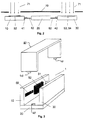
- connection means in the form of film hinges 60, 61, 62 and 63 are interconnected.
- the parts 10 and 30 have optical Structures 50, 51, 52, 53 and 54 that together make up a miniature spectrometer form.
- the part 10 is a lattice girder part and has 11 on its wall surface a structure 50 in which the image plane lies and which, for example, is one Can be a recess for a detector, a flat grid 52 and a Connection structure 51.
- the wall surface 13 is 40 in with two adjustment means Form of cuboid projections 41 provided. Between these two Projections 41, the two film hinges 60 and 61 are arranged.
- the lower wall surface 14 and the remaining wall surfaces, of which the Wall surface 12 can be seen are not structured.
- the further component 30 has two on its wall surface 31 Concave mirror structures 53 and 54 which are arranged side by side.
- the Wall surface 34 also carries adjustment means 40 in the form of cuboid Protrusions 42, between which the Fimschamiere 62 and 63 are located.
- the wall surfaces 23 and 24 on the film hinges 60 to 64 is connected to components 10 and 30.
- a total of four recesses 43 are arranged as adjustment means 40, the Dimensions are matched to the projections 41 and 42 so that the Parts 10 and 30 are inserted in a form-fitting manner in the plug-in plate 20 can.
- the film hinge must first 60, 61, 62, 63 are completely removed, as described below becomes.
- the arrangement of the adjustment means 40 is the spatial assignment of the optical Components 50 to 54 clearly defined.
- FIGS. 4a, 4b and 5a and 5b Further embodiments of the adjustment means are shown in FIGS. 4a, 4b and 5a and 5b, the connecting means for the sake of clarity were omitted.
- 4a are paired snap elements 44a and 44b formed on part 30.
- Each snap element consists of a long one Leg 45, which is arranged at right angles on the component 30, and one short leg 46 arranged at right angles thereto, which at the free end of the long leg 45 is formed.
- the plug-in plate 20 has as a corresponding Adjustment means 40 recesses in the form of openings 43 into which the Snap elements 44a and 44b can be inserted. Since the Snap element pairs 44a and 44b are each designed to be elastic these are moved towards each other for insertion, so that the two short Leg 46 fit into the opening 43 of the plug-in plate 20.
- FIG. 5a A further embodiment is shown in FIG. 5a.
- the plug-in plate 20 has as adjustment means 40 a T-shaped rail 47, the corresponding one Counterpart in component 30 in the form of an H-shaped recess 48 is provided.
- the plug-in plate 20 can by means of this T-shaped section or T-shaped rail 47 inserted into the H-shaped recess 48 become. indicated this is shown in Fig. 5b.
- Both components 20 and 30 are fixed to each other in this way.
- component 30 preferably has a lateral projection on (not visible in Fig. 5a, b), which is used for stop adjustment.
- the component 30 has a receptacle for a glass fiber and that Component 10 is a concave curved grating 52. Outside of that in FIGS. 6 and 7 Another sectional plane is shown in component 30 Recording for a detector.
- step Structures 40, 43 reached.
- the edge of these structures is determined by the mask and is therefore high Precision aligned to the other structures.
- a durable connection of the components can be during or after the Assembly, e.g. by applying an adhesive, by laser welding or Establish similar connection techniques at the joints of the individual parts.
Abstract
Description
Die Erfindung betrifft ein miniaturisiertes optisches Bauelement aus mindestens zwei Bauteilen, von denen mindestens ein Bauteil optische Mikrostrukturen aufweist, wobei die Bauteile beabstandet zueinander über mindestens einen Abstandsformkörper miteinander verbunden sind, und die Bauteile und der Abstandsformkörper selbstjustierende Justagemittel für eine präzise Relativjustage beim Zusammensetzen der Bauteile und des Abstandsformkörpers aufweisen. Die Erfindung bezieht sich auch auf ein Verfahren zur Herstellung solcher miniaturisierter optischer Bauelemente.The invention relates to a miniaturized optical component comprising at least two components, of which at least one component is optical microstructures has, the components spaced from each other via at least one Spacer bodies are interconnected, and the components and the Spacer body self-adjusting adjustment means for a precise Relative adjustment when assembling the components and the Have molded spacer. The invention also relates to a Process for the production of such miniaturized optical components.
Komplexe optische miniaturisierte Bauelemente wurden bisher in der Weise hergestellt, daß die Einzelkomponenten wie Beugungsgitter, Spiegel usw. in getrennten Fertigungsverfahren hergestellt, dann sorgfältig justiert und montiert werden mußten. Für die Massenfertigung waren diese Verfahren nicht geeignet, weil jedes optische miniaturisierte Bauelement die aufwendige Justierung der Einzelkomponenten erforderlich machte.So far, complex optical miniaturized components have been made in this way manufactured that the individual components such as diffraction gratings, mirrors, etc. in separate manufacturing processes, then carefully adjusted and assembled had to be. These processes were not for mass production suitable because each optical miniaturized component is complex Adjustment of the individual components made necessary.
Um hier Abhilfe zu schaffen, wurde in der DE 3611246 C2 vorgeschlagen, die optischen Komponenten des Bauelementes einschließlich des oder der Echelette-Gitter auf röntgenlithographischem, röntgentiefenlithographischgalvanoplastischem oder hiervon abgeleiteten abformtechnischem Wege herzustellen, wobei die Gitterlinien parallel zur Röntgenstrahlung verlaufen. Dieses Verfahren hat jedoch den Nachteil, daß dreidimensionale Strukturen, wie z.B. in zwei Ebenen gekrümmte Spiegel nicht hergestellt werden können, weil in Richtung der Röntgenstrahlung wegen der geradlinigen Ausbreitung keine Strukturierung möglich ist.In order to remedy this, DE 3611246 C2 proposed that optical components of the component including the or Echelette grating on X-ray lithography, X-ray depth lithography galvanoplastic or derived from this impression technique to produce, the grid lines parallel to the X-rays. However, this method has the disadvantage that three-dimensional structures, such as. mirrors curved in two planes cannot be produced, because in the direction of x-rays because of the linear propagation no structuring is possible.
Bei den mikrotechnischen Verfahren eröffnet die LIGA-Technik eine große Form- und Materialvielfalt sowie eine hohe Präzision der Detailstrukturen (s. z.B. W. Ehrfeld. H. Lehr, Rad. Physics and Chemistry, 1995. Pergamon Press). Dabei entstehen Formeinsätze, die durch verschiedene Abformtechniken als Kunststoff-, Metall- oder Keramikteil repliziert werden können und eine Strukturierung nur an den Seitenwänden des Hohlkörpers aufweisen.LIGA technology opens up a great deal in terms of microtechnical processes Variety of shapes and materials as well as high precision of the detail structures (see e.g. W. Ehrfeld. H. Lehr, Rad. Physics and Chemistry, 1995. Pergamon Press). This creates mold inserts that are different Impression techniques can be replicated as plastic, metal or ceramic parts can and structuring only on the side walls of the hollow body exhibit.
Durch die Abformung eines mittels LIGA-Technik gefertigten, geöffneten Hohlkörpers wird dessen Seitenwandprofil (z.B. Gitter, Spiegel) übertragen. Die optischen Elemente weisen dabei nur in einer Ebene eine Krümmung auf, so daß eine Fokussierung des Lichts nur in dieser Ebene stattfindet. Bei der Herstellung miniaturisierter optischer Bauelemente wird zur Führung und Begrenzung des Lichtwegs in der dazu senkrechten Richtung deshalb eine Schichtwellenleiteranordnung eingesetzt, deren Höhe beschränkt ist (vgl. z.B. Interdisciplinary Science Reviews, 1993, 18, No. 3, S. 273).By taking an impression of an open one made using LIGA technology The side wall profile (e.g. grille, mirror) is transferred to the hollow body. The optical elements have a curvature only in one plane, so that the light is focused only in this plane. In the Manufacture of miniaturized optical components is used for guidance and Limitation of the light path in the direction perpendicular to it is therefore a Layer waveguide arrangement used, the height of which is limited (see e.g. Interdisciplinary Science Reviews, 1993, 18, No. 3, p. 273).
Es ist daher wünschenswert, eine Freistrahloptik bei miniaturisierten Bauelementen zu realisieren, bei der die Lichtstrahlen sich ungehindert im miniaturisierten optischen Bauelement ausbreiten können. Es muß daher nach einem Herstellungsverfahren gesucht werden, das es gestattet, in zwei Ebenen gekrümmte Seitenwände des miniaturisierten Bauelementes zu fertigen und damit eine Fokussierung des Lichts in zwei zueinander senkrechten Ebenen sowie eine verbesserte Auflösung zu realisieren.It is therefore desirable to use a free beam optics for miniaturized Realize components in which the light rays unhindered in can spread miniaturized optical component. It therefore has to be done a manufacturing process that allows two levels to produce curved side walls of the miniaturized component and thus focusing the light in two mutually perpendicular planes as well as to realize an improved resolution.
Aus der US 5.521.763 ist ein optisches Bauelement bekannt, das allerdings kein miniaturisiertes Bauelement mit optischer Mikrostruktur darstellt. Auf einer gemeinsamen Grundplatte sind eine toroidale Linse, ein polygonaler Spiegel sowie ein Detektor angeordnet. Es handelt sich jedoch nicht um selbstjustierende Justagemittel, da die Steckelemente in Langlöchern eingesetzt werden. Eine Fixierung erfolgt mit Klebstoff und Federn.An optical component is known from US 5,521,763, however does not represent a miniaturized component with an optical microstructure. On A common base plate is a toroidal lens, a polygonal Mirror and a detector arranged. However, it is not about self-adjusting means of adjustment because the plug-in elements are inserted in elongated holes become. It is fixed with adhesive and springs.
Das japanische Abstract 61-144609(A) bezeichnet ein optisches Kuppelelement, das zwei optische Komponenten umfaßt, die auf einer vertikalen Grundplatte befestigt sind. Über die Art der Befestigung und der Justierung werden keine Angaben gemacht.Japanese abstract 61-144609 (A) denotes an optical coupling element, which comprises two optical components mounted on a vertical base plate are attached. About the type of attachment and adjustment are not Information provided.
Aus der EP 0 194 613 ist ein Verfahren zur justierten Montage optischer Bauteile bekannt. Die optischen Bauteile werden mit genauer Lage und Ausrichtung hergestellt und in definierter Weise zusammengesetzt und fixiert. Als Justageelemente weisen die Bauteile stufenartige Strukturen auf. Über Abstandsformkörper, die entsprechende Justagestrukturen besitzen, werden die optischen Bauteile im Abstand zueinander angeordnet. Die Einzelteile müssen für die Montage zusammengestellt werden, wobei darauf geachtet werden muß. welche Bauteile wie zusammengefügt werden müssen.EP 0 194 613 describes a method for adjusting optical assembly Components known. The optical components are with exact location and Alignment created and assembled and fixed in a defined manner. The components have step-like structures as adjustment elements. about Spacer moldings that have appropriate adjustment structures, the optical components arranged at a distance from each other. The items need be assembled for assembly, taking care. which components have to be put together and how.
Es ist daher Aufgabe der Erfindung, ein miniaturisiertes optisches Bauelement aus mehreren Teilen bereitzustellen, deren Montage vereinfacht ist. Es ist auch Aufgabe der Erfindung, ein Verfahren zur Herstellung solcher optischer Bauelemente hereitzustellen, wobei eine Massenfertigung möglich sein soll.It is therefore an object of the invention to provide a miniaturized optical component to be provided from several parts, the assembly of which is simplified. It is also Object of the invention, a method for producing such optical To produce components, whereby mass production should be possible.
Das miniaturisierte optische Bauelement ist dadurch gekennzeichnet, daß mindestens zwei Teile über Verbindungsmittel miteinander verbunden sind und eine zusammenhängende Einheit bilden.The miniaturized optical component is characterized in that at least two parts are connected to one another via connecting means and form a coherent unit.
Die Verbindungsmittel gewährleisten eine Zuordnung der miteinander verbundenen Einzelteile, so daß bei der Montage die zusammengehörigen Bauteile sofort erkennbar sind. Die Verbindungsmittel sind vorzugsweise so ausgestaltet und an den Bauteilen angebracht, daß der Zusammenbau eindeutig festgelegt ist.The connecting means ensure an association of the two connected individual parts, so that the related together during assembly Components are immediately recognizable. The connecting means are preferably so designed and attached to the components that the assembly clearly is set.
Ein weiterer Vorteil besteht darin, daß die Verbindungsmittel eine Verliersicherung darstellen.Another advantage is that the connecting means Represent loss protection.
Gerade bei der Massenfertigung werden die Einzelbauteile im Set angeboten und erst beim Anwender zusammengebaut. Damit die einzelnen zusammengehörigen Teile nicht verloren gehen, ist es von Vorteil, wenn alle Bauteile über geeignete Verbindungsmittel miteinander verbunden sind und eine zusammenhängende Einheit bilden. Diese Verbindungsmittel sind vorzugsweise elastisch und können beispielsweise elastische Faserbändchen oder Filmscharniere sein. Vorteilhafterweise sind diese Verbindungsmittel aus demselben Material gefertigt wie die Bauteile, wodurch auch der Herstellungsvorgang vereinfacht wird.The individual components are offered in a set, especially for mass production and only assembled by the user. So that the individual related parts are not lost, it is beneficial if all Components are connected to one another via suitable connecting means and form a coherent unit. These are lanyards preferably elastic and can, for example, elastic fiber ribbon or be film hinges. These connecting means are advantageously made of made of the same material as the components, which means that the Manufacturing process is simplified.
Die elastischen Verbindungsmittel sind vorzugsweise an der nicht strukturierten Wandfläche der Teile angeordnet, was den Vorteil hat, daß die einzelnen Teile zusammengefügt werden können, ohne daß die Verbindungsmittel durchtrennt werden müssen. Die Einzelteile können auch wieder auseinandergebaut werden und bleiben über die Verbindungsmittel miteinander verbunden.The elastic connecting means are preferably on the non-structured Wall surface of the parts arranged, which has the advantage that the individual parts can be assembled without cutting through the connecting means Need to become. The individual parts can also be disassembled and remain connected to each other via the connecting means.
Ein gesonderter Justagevorgang bei der Montage der einzelnen Teile oder eine Nachjustage entfallen, weil sich durch die an den Teilen angebrachten Justagemittel die gewünschte gegenseitige Ausrichtung und Positionierung der Teile automatisch einstellt. Beim Zusammensetzen der Teile wird eine präzise Relativjustage von ca. 1 µm erreicht. Als Justagemittel können Vorsprünge, Vertiefungen, Steckelemente, Schnappelemente oder Schiebeelemente vorgesehen sein. Welche Art Justagemittel verwendet wird, hängt nicht nur von der Anzahl der Teile und deren gegenseitiger Anordnung, sondern auch von der gewünschten Präzision ab. Die Justagemittel wirken vorzugsweise formschlüssig zusammen.A separate adjustment process when assembling the individual parts or a Readjustments are not necessary because the parts attached to them Adjustment means the desired mutual alignment and positioning of the Automatically adjusts parts. When assembling the parts it becomes precise Relative adjustment of approx. 1 µm achieved. Projections, Wells, plug-in elements, snap elements or sliding elements be provided. The type of adjustment device used does not only depend on the number of parts and their mutual arrangement, but also on the desired precision. The adjustment means preferably act form-fitting together.
Dadurch, daß mehrere Einzelteile hochpräzise zusammengebaut werden können, ist die geometrische Ausführungsform des optischen Bauelements variabel. Dies ist insbesondere dann wichtig, wenn z.B. Miniaturspektrometer hergestellt werden sollen, weil auf diese Art und Weise eine Freistrahloptik realisiert werden kann.The fact that several individual parts are assembled with high precision can, is the geometric embodiment of the optical component variable. This is particularly important if e.g. miniature spectrometer should be produced because in this way a free jet optics can be realized.
Zwischen den Bauteilen verbleibt ein Freiraum, so daß die Lichtausbreitung nur im materialfreien Raum stattfindet. Dadurch wird der Vorteil erzielt, daß keine auflösungsvermindernde Dispersion, wie z.B. in Glas oder Kunststoff auftritt.A free space remains between the components so that the light propagates only takes place in a material-free room. This has the advantage that no resolution-reducing dispersion, e.g. in glass or plastic occurs.
Vorzugsweise sind die optischen Mikrostrukturen nur auf einer Seite der Teile angeordnet, was die Herstellung mit entsprechenden Formen vereinfacht.The optical microstructures are preferably only on one side of the parts arranged, which simplifies the production with appropriate shapes.
Vorzugsweise ist der Abstandsformkörper eine Grundplatte, insbesondere eine für die übrigen Teile gemeinsame Steckplatte, deren Justagemittel mit entsprechenden Justagemitteln an den übrigen Teilen zusammenwirken. Die Justagemittel können Ausnehmungen und/oder Vorsprünge sein, in die die übrigen Teile mit entsprechenden Justagemitteln eingesteckt werden. Insbesondere bei der Massenfertigung miniaturisierter Formenkörper kann durch unterschiedlich ausgebildete Steckplatten die gegenseitige Zuordnung der übrigen Teile auf einfache Weise variiert werden, ohne daß die übrigen Einzelbauteile, die mit Strukturen an ihren Oberflächen versehen sind, verändert werden müssen. Dadurch wird eine hohe Flexibilität unter Beibehaltung der Präzision bezüglich der gegenseitigen Anordnung erzielt.The shaped spacer body is preferably a base plate, in particular a base plate for the other parts common plug-in board, the adjustment means with the corresponding adjustment means on the other parts. The Adjustment means can be recesses and / or projections into which the remaining parts are inserted with appropriate adjustment means. Particularly in the mass production of miniaturized moldings through differently designed plug-in boards the mutual assignment of the remaining parts can be varied in a simple manner without the rest Individual components with structures on their surfaces, need to be changed. This creates a high degree of flexibility Maintaining the precision with respect to the mutual arrangement achieved.
Die Justagemittel sind vorzugsweise an die Teile angeformt oder in diese eingeformt. Die Herstellung und Anbringung der Justagemittel wird somit in den Herstellungsvorgang der Teile verlagert, so daß die Justierung der Teile durch die Form für die Herstellung der Teile festgelegt wird. Es sind somit lediglich hochpräzise Formen erforderlich, mit denen eine Massenfertigung hochpräziser Bauteile mit integrierten Justagemitteln möglich ist.The adjustment means are preferably molded onto or into the parts formed. The manufacture and attachment of the adjustment means is thus in shifted the manufacturing process of the parts so that the adjustment of the parts is determined by the mold for the manufacture of the parts. So there are only high-precision molds required with which a mass production high-precision components with integrated adjustment means is possible.
Wenn das optische Bauelement ein miniaturisiertes Spektrometer ist, weist das erste Bauteil vorzugsweise mindestens eine planare oder gekrümmte Beugungsgitterstruktur und/oder mindestens eine Anschlußstruktur für polychromatisches und/oder monochromatisches Licht auf. In einer speziellen Ausführungsform zeigt das im zusammengesetzten Zustand dem als Gitterträgerteil ausgebildeten Bauteils gegenüberliegende Teil mindestens eine planare oder gekrümmte Hohlspiegelstruktur.If the optical component is a miniaturized spectrometer, this indicates first component preferably at least one planar or curved Diffraction grating structure and / or at least one connection structure for polychromatic and / or monochromatic light. In a special Embodiment shows this in the assembled state as Lattice girder part formed component opposite part at least one planar or curved concave mirror structure.
Gemäß einer weiteren Ausführungsform kann das erste Bauteil eine gekrümmte Beugungsgitterstruktur und ein zweites Bauteil mindestens eine Anschlußstruktur für Licht aufweisen.According to a further embodiment, the first component can be a curved one Diffraction grating structure and a second component at least one Have connection structure for light.
Vorzugsweise weist mindestens ein Bauteil mindestens eine Ausnehmung zur Aufnahme eines Detektors auf.At least one component preferably has at least one recess Recording a detector.
Damit das Mikrospektrometer lichtdicht zur Umgebung abgeschlossen ist, ist mindestens ein Abdeckteil vorgesehen, das Justagemittel aufweist, die mit entsprechenden Justagemitteln an mindestens einem der übrigen Bauteile zusammenwirken. Das Abdeckteil kann auch U-förmig sein und somit drei Wände aufweisen.So that the microspectrometer is sealed light-tight to the environment at least one cover part is provided, which has adjustment means which with corresponding adjustment means on at least one of the other components interact. The cover can also be U-shaped and therefore three Have walls.
Das Verfahren zur Herstellung solcher miniaturisierter Bauelemente ist dadurch gekennzeichnet, daß die Bauteile und der mindestens eine Abstandsformkörper zusammen mit ihren selbstjustierenden Justagemitteln jeweils in einem Schritt auf abformtechnischem Wege hergestellt werden, wobei mindestens zwei Teile gemeinsam und über Verbindungsmittel als zusammenhängende Einheit gefertigt werden.The process for producing such miniaturized components is thereby characterized in that the components and the at least one molded spacer together with their self-adjusting adjustment means in one step are produced by molding, with at least two parts together and via connecting means as a coherent unit are manufactured.
Die Verbindungsmittel bestehen vorzugsweise aus demselben Material wie die Bauteile und können daher vorteilhafterweise im selben Fertigungsschritt hergestellt werden.The connecting means are preferably made of the same material as that Components and can therefore advantageously in the same manufacturing step getting produced.
Es ist auch möglich, bei oder vor der Fertigung der Bauteile vorgefertigte Verbindungsmittel einzulegen, wobei die Verbindungsmittel auch aus anderen Materialien als die Bauteile bestehen können.It is also possible to use prefabricated components during or before the components are manufactured Insert connecting means, the connecting means also from others Materials than the components can consist of.
Vorteilhafterweise wird ein mikrotechnisch hergestellter Formeinsatz verwendet, weil die abformtechnische Herstellung eine kostengünstige Fertigung in großen Stückzahlen erlaubt.A microtechnically produced mold insert is advantageous used because the impression-making production is inexpensive Production in large numbers allowed.
Durch die abformtechnische Herstellung der Teile unter Verwendung eines mikrotechnischen Formeinsatzes können Funktionseinheiten des Spektrometers mit ganz unterschiedlichen Abmessungen und Präzisionsanforderungen wie Wände, Justagemittel und optisches Gitter gleichzeitig gefertigt werden. Daraus resultiert ein kostengünstiger Herstellungsprozeß bei gleichzeitig hoher Qualität und Präzision.Due to the molding of the parts using a microtechnical mold insert can function units of the spectrometer with very different dimensions and precision requirements such as Walls, adjustment means and optical grids can be manufactured at the same time. from that the result is an inexpensive manufacturing process with high quality and precision.
Weil die Bauteile mit der jeweils zugeordneten Justagestruktur gemeinsam hergestellt werden und dazu ein mikrotechnischer Formeinsatz verwendet wird, wird eine sehr hohe Präzision von ca. 1µm für die Relativlage der Teile beim Zusammenbau erreicht.Because the components together with the assigned adjustment structure are produced and a microtechnical mold insert is used for this, a very high precision of approx. 1µm for the relative position of the parts in the Assembly achieved.
Weil sich in einer speziellen Ausgestaltung die Mikrostrukturen nur auf jeweils einer Seite der Teile befinden, ist für die abformtechnische Herstellung nur ein im wesentlichen planarer Formeinsatz mit Mikrostrukturen auf der Oberseite notwendig. Ein solcher Formeinsatz kann aber besonders gut mit mikrotechnischen Verfahren realisiert werden.Because in a special configuration the microstructures only apply to each one side of the parts is only one for impression-making essentially planar mold insert with microstructures on the top necessary. Such a mold insert is particularly good with microtechnical processes can be realized.
Bei der abformtechnischen Fertigung des Spektrometers können Einlegeteile vorgesehen werden. Diese Einlegeteile werden in das Formnest eingebracht und bei der Formfüllung von der Formmasse teilweise oder vollständig umschlossen. Dabei kann es vorteilhaft sein, einen möglichst großen Bereich der Form bereits durch die Einlegeteile auszufüllen, so daß nur wenig Raum für die Formmasse verbleibt.Insert parts can be used in the molding of the spectrometer be provided. These inserts are placed in the mold cavity and partially or completely when filling the molding compound enclosed. It can be advantageous to have the largest possible area the form already to be filled in by the inserts, so that there is little space remains for the molding compound.
Durch die Verwendung von Einlegeteilen hat man den Vorteil, daß Schwindung und Verzüge des Spektrometers bei der abformtechnischen Herstellung minimiert werden. Weiterhin ist es vorteilhaft, wenn die Einlegeteile aus einem stabilen Werkstoff (z.B. was Temperatur- und Klimaschwankungen angeht) bestehen. Durch diese Maßnahme erhält das Spektrometer insgesamt eine hohe Stabilität.By using inserts one has the advantage that Shrinkage and warpage of the spectrometer in the impression technique Manufacturing can be minimized. It is also advantageous if the Inserts made of a stable material (e.g. what temperature and Climate fluctuations) exist. With this measure the Spectrometer overall high stability.
Als bevorzugtes Herstellungsverfahren sind Spritzgieß-, Reaktionsgieß- oder Spritzprägeverfahren möglich. Alle Teile können als zusammenhängende Einheit gefertigt werden, wobei entsprechende Verbindungsmittel zwischen den einzelnen Bauteilen beim Herstellungsvorgang mit ausgebildet werden. Die einzelnen Teile können auf diese Art und Weise nicht verloren gehen. Der Anwender kann die einzelnen Bauteile an den Verbindungsmitteln durchtrennen und dann die jeweiligen Bauteile miteinander verbinden. Je nach Art und Elastizität der Verbindungsmittel sowie deren Anbringung an den Teilen ist es auch möglich, die einzelnen Teile verbunden zu lassen und trotzdem zusammenstecken zu können.Injection molding, reaction molding or Spray embossing process possible. All parts can be considered contiguous Unit are manufactured, with appropriate connecting means between the individual components are formed during the manufacturing process. The individual parts cannot be lost in this way. The The user can cut through the individual components on the connecting means and then connect the respective components together. Depending on the type and It is elasticity of the connecting means and their attachment to the parts also possible to leave the individual parts connected and still to be able to put together.
Wenn die Teile nach dem Formvorgang noch weiter bearbeitet werden sollen, wie dies bei optischen Bauteilen der Fall ist, die z.B. noch verspiegelt werden müssen, empfiehlt es sich, die Teile so herzustellen, daß alle mit Strukturen versehenen Wandflächen der Teile in einer gemeinsamen Ebene liegen. Es ist dadurch möglich, die aus mehreren Teilen bestehende Einheit in eine Beschichtungsanlage einzuführen und den Beschichtungsvorgang lediglich von einer Seite aus durchzuführen.If the parts are to be further processed after the molding process, as is the case with optical components, e.g. still be mirrored , it is advisable to manufacture the parts so that they all have structures provided wall surfaces of the parts lie in a common plane. It is This enables the unit consisting of several parts into one Introduce coating system and the coating process only from from one side.
Es ist damit auf einfache Weise möglich, die in einer gemeinsamen Ebene liegenden Strukturen flächen- und/oder strukturselektiv zu bearbeiten. Als geeignete Verfahren sind hierfür Plasmaverfahren, Aufdampfverfahren. Sputtern oder Galvanisierverfahren denkbar. Vorzugsweise wird eine flächen- und/oder strukturselektive Verspiegelung durchgeführt.It is thus easily possible in a common plane to process lying structures in a surface and / or structure selective manner. As Suitable processes are plasma processes, vapor deposition processes. Sputtering or electroplating processes possible. Preferably, an area and / or structure-selective mirroring performed.
Beispielhafte Ausführungsformen der Erfindung werden nachfolgend anhand der Zeichnungen näher erläutert. Es zeigen:
- Fig. 1
- drei miteinander verbundene Teile eines Bauelements,
- Fig. 2
- die in Fig. 1 gezeigte Einheit aus drei Teilen in Seitenansicht während eines Beschichtungsvorgangs,
- Fig. 3
- das aus drei Teilen zusammengesetzte Bauelement in perspektivischer Darstellung,
- Fign. 4a und 4b
- zwei Teile mit einer Schnappverbindung vor und nach dem Zusammensetzen,
- Fign. 5a und 5b
- zwei Teile mit einer Schiebeverbindung vor und nach dem Zusammensetzen, und
- Fign. 6 und 7
- die miteinander verbundenen Teile eines Bauelementes vor und nach dem Zusammenfügen.
- Fig. 1
- three interconnected parts of a component,
- Fig. 2
- the unit shown in Fig. 1 from three parts in side view during a coating process,
- Fig. 3
- the component composed of three parts in perspective,
- FIGS. 4a and 4b
- two parts with a snap connection before and after assembly,
- FIGS. 5a and 5b
- two parts with a sliding connection before and after assembly, and
- FIGS. 6 and 7
- the interconnected parts of a component before and after assembly.
In der Fig. 1 sind drei plattenförmige Teile 10, 20 und 30 perspektivisch
dargestellt, die über Verbindungsmittel in Form von Filmscharnieren 60, 61,
62 und 63 miteinander verbunden sind. Die Teile 10 und 30 besitzen optische
Strukturen 50, 51, 52, 53 und 54, die zusammen ein Miniaturspektrometer
bilden. Das Teil 10 ist ein Gitterträgerteil und besitzt auf seiner Wandfläche 11
eine Struktur 50, in welcher die Bildebene liegt und die beispielsweise eine
Aussparung für einen Detektor sein kann, ein ebenes Gitter 52 sowie eine
Anschlußstruktur 51. Die Wandfläche 13 ist mit zwei Justagemitteln 40 in
Form von quaderförmigen Vorsprüngen 41 versehen. Zwischen diesen beiden
Vorsprüngen 41 sind die beiden Filmscharniere 60 und 61 angeordnet. Die
untere Wandfläche 14 sowie die übrigen Wandflächen, von denen noch die
Wandfläche 12 zu sehen ist, sind nicht strukturiert.In Fig. 1, three plate-shaped
Das weitere Bauteil 30 besitzt auf seiner Wandfläche 31 zwei
Hohlspiegelstrukturen 53 und 54, die nebeneinander angeordnet sind. Die
Wandfläche 34 trägt Justagemittel 40 ebenfalls in Form von quaderförmigen
Vorsprüngen 42, zwischen denen sich die Fimschamiere 62 und 63 befinden.
Zwischen den Teilen 10 und 30 befindet sich die als Steckplatte ausgebildete
Grundplatte 20, die über ihre Wandflächen 23 und 24 über die Filmschamiere
60 bis 64 mit den Bauteilen 10 und 30 verbunden ist. In der Wandfläche 21
sind als Justagemittel 40 insgesamt vier Ausnehmungen 43 angeordnet, deren
Abmessungen auf die Vorsprünge 41 bzw. 42 abgestimmt sind, so daß die
Teile 10 und 30 in die Steckplatte 20 formschlüssig eingesteckt werden
können. Dazu müssen in dieser Ausführungsform zunächst die Filmschamiere
60, 61, 62, 63 vollständig entfernt werden, wie nachfolgend noch beschrieben
wird. Durch die beim Herstellungsvorgang der Teile 10, 20 und 30 festgelegte
Anordnung der Justagemittel 40 ist die räumliche Zuordnung der optischen
Komponenten 50 bis 54 eindeutig festgelegt. The
Bevor die einzelnen Teile 10, 20 und 30 zusammengesteckt werden, können sie
einer Oberflächenbehandlung unterzogen werden, wie dies in der Fig. 2
dargestellt ist. Da alle optischen Strukturen 50 bis 54 in einer Ebene liegen,
können mittels einer einzigen Maske 70 alle Bauteile struktur- oder
flächenselektiv beschichtet werden, wobei die Pfeile 71 den Materialfluß
während des Beschichtungsvorgangs kennzeichnen.Before the
Nachdem die Teile auf diese Art und Weise oberflächenbearbeitet sind, werden
die Teile 10, 20 und 30 an den Filmscharnieren 60 bis 64 durchtrennt bzw. die
Filmscharniere werden an der Wandfläche 13 des Teils 10 bzw. der
Wandfläche 34 des Teils 30 abgetrennt, so daß die Teile 10 und 30
ungehindert in die Steckplatte 20 zur Bildung eines miniaturisierten optischen
Bauelements 1 in Form eines Spektrometers eingesteckt werden können. Dies
ist in der Fig. 3 dargestellt. Die gegenseitige Ausrichtung und Anordnung der
optischen Komponenten 50 bis 54 ist damit eindeutig vorgegeben, ohne daß es
eines weiteren Justagevorgangs bedarf. Der Aufbau wird dadurch weiter
stabilisiert, daß ein U-förmiges Abdeckteil 80 mit weiteren Justageelementen
40 aufgesteckt wird. Das Mikrospektrometer wird dadurch auch vor
Lichteinfall von außen geschützt.After the parts are finished in this way,
cut the
Weitere Ausführungsformen der Justagemittel sind in den Fign. 4a, 4b und 5a
sowie 5b dargestellt, wobei die Verbindungsmittel der Übersichtlichkeit halber
weggelassen wurden. In der Fig. 4a sind paarweise Schnappelemente 44a und
44b am Teil 30 angeformt. Jedes Schnappelement besteht aus einem langen
Schenkel 45, der rechtwinklig am Bauteil 30 angeordnet ist, und einem
rechtwinklig dazu angeordneten kurzen Schenkel 46, der am freien Ende des
langen Schenkels 45 angeformt ist. Die Steckplatte 20 besitzt als entsprechende
Justagemittel 40 Ausnehmungen in Form von Durchbrechungen 43, in die die
Schnappelemente 44a und 44b eingeführt werden können. Da die
Schnappelementpaare 44a und 44b jeweils elastisch ausgebildet sind, können
diese zum Einführen aufeinander zu bewegt werden, so daß die beiden kurzen
Schenkel 46 in die Durchbrechung 43 der Steckplatte 20 passen. Wenn die
Schnappelemente 44a und 44b vollständig eingesteckt sind, wie dies in der Fig.
4b dargestellt ist, bewegen sich die beiden Schnappelemente 44a und 44b
wieder in ihre ursprüngliche Position zurück, wobei die kurzen Schenkel 46
die Steckplatte 20 hintergreifen und auf diese Art und Weise für einen festen
unverrückbaren Sitz des Bauteils 30 sorgen.Further embodiments of the adjustment means are shown in FIGS. 4a, 4b and 5a
and 5b, the connecting means for the sake of clarity
were omitted. 4a are paired
In der Fig. 5a ist eine weitere Ausführungsform dargestellt. Die Steckplatte 20
besitzt als Justagemittel 40 eine T-förmige Schiene 47, deren entsprechendes
Gegenstück im Bauteil 30 in Form einer H-förmigen Ausnehmung 48
vorgesehen ist. Die Steckplatte 20 kann mittels dieses T-förmigen Abschnitts
oder T-förmigen Schiene 47 in die H-förmige Ausnehmung 48 eingeschoben
werden. wies dies in der Fig. 5b dargestellt ist. Beide Bauteile 20 und 30 sind
auf diese Weise zueinander fixiert. Um eine seitliche Verschiebung zu
verhindern, weist vorzugsweise die Komponente 30 einen seitlichen Vorsprung
auf (nicht sichtbar in Fig. 5a,b), der zur Anschlagsjustage dient.A further embodiment is shown in FIG. 5a. The plug-in
In der Fig. 6 ist eine zusammenhängende Einheit aus drei Teilen 10, 20 und 30
dargestellt, wobei die Filmscharniere 60, 62 jeweils an der Unterseite 14, 24,
24 der Teile 10, 20 und 30 angeordnet sind. Während die Filmscharniere
gemäß Fig. 1 aus steifem Material sein konnten, weil sie ohnehin abgetrennt
werden, sind die hier gezeigten Filmscharniere 60, 62 elastisch, so daß sie
beim Zusammenfügen (s. Fig. 7) an den Teilen 10, 20 und 30 verbleiben
können. Das Bauteil 30 weist eine Aufnahme für eine Glasfaser auf und das
Bauteil 10 ein konkav gekrümmtes Gitter 52. Außerhalb der in Fig. 6 und 7
dargestellten Schnittebene befindet sich in dem Bauteil 30 eine weitere
Aufnahme für einen Detektor.6 is a coherent unit from three
Weil sich in dieser speziellen Ausgestaltung der Erfindung Mikrostrukturen nur
auf jeweils einer Seite der Elemetne 10, 20, 30 befinden, ist für die
abformtechnische Herstellung nur ein im wesentlichen planarer Formeinsatz
mit Mikrostrukturen auf der Oberseite notwendig. Ein solcher Formeinsatz
kann aber besonders gut mit mikrotechnischen Verfahren realisiert werden.Because in this special embodiment of the invention there are only microstructures
on each side of the
Die Justage wird in diesem Ausführungsbeispiel durch stufenförmige
Strukturen 40, 43 erreicht. In einem lithographischen Herstellungsprozeß wird
die Kante dieser Strukturen durch die Maske bestimmt und ist daher mit hoher
Präzision zu den weiteren Strukturen ausgerichtet.The adjustment is made in this embodiment by
Eine haltbare Verbindung der Bauteile läßt sich während oder nach der Montage, z.B. durch das Auftragen eines Klebers, durch Laserschweißen oder ähnliche Verbindungstechniken an den Stoßstellen der Einzelteile herstellen. A durable connection of the components can be during or after the Assembly, e.g. by applying an adhesive, by laser welding or Establish similar connection techniques at the joints of the individual parts.
- 1010
- Bauteilcomponent
- 1111
- Wandflächewall surface
- 1212
- Wandflächewall surface
- 1313
- Wandflächewall surface
- 1414
- Wandflächewall surface
- 2020
- Grundplattebaseplate
- 2121
- Wandflächewall surface
- 2222
- Wandflächewall surface
- 2323
- Wandflächewall surface
- 2424
- Wandflächewall surface
- 3030
- Bauteilcomponent
- 3131
- Wandflächewall surface
- 3232
- Wandflächewall surface
- 3333
- Wandflächewall surface
- 3434
- Wandflächewall surface
- 4040
- Justagemitteladjustment means
- 4141
- Vorsprunghead Start
- 4242
- Vorsprunghead Start
- 4343
- Ausnehmungrecess
- 44a44a
- Schnappelementsnap element
- 44b44b
- Schnappelementsnap element
- 4545
- langer Schenkellong leg
- 4646
- kurzer Schenkelshort leg
- 4747
- T-förmiger AbschnittT-shaped section
- 4848
- H-förmige AusnehmungH-shaped recess
- 5050
- Bildebeneimage plane
- 5151
- Anschlußstrukturterminal structure
- 5252
- Plangitterstruktur Plane grating structure
- 5353
- HohlspiegelstrukturConcave mirror structure
- 5454
- HohlspiegelstrukturConcave mirror structure
- 6060
- FimscharniereFimscharniere
- 6161
- Filmscharnierefilm hinges
- 6262
- Filmscharnierefilm hinges
- 6363
- Filmscharnierefilm hinges
- 7070
- Maskemask
- 7171
- Pfeile für MaterialflußArrows for material flow
- 8080
- Abdeckteilcover
Claims (22)
- Miniaturised optical component which before assembly of the individual parts consists of at least two devices, of which at least one device has optical microstructures, wherein the devices (10, 30) are connected to one another at a distance from one another via at least one spacer moulding (20), and the devices (10, 30) and the spacer moulding (20) have self-adjusting adjustment means (40) for precise relative adjustment when assembling the devices (10, 30) and the spacer moulding, characterised in that at least two parts (10, 20, 30) are connected to one another via connecting means (60-63) as lost security and form a coherent unit.
- Component according to claim 1, characterised in that the spacer moulding is a plug-in panel common to the devices (10, 30), the adjustment means (40) of which cooperate with corresponding adjustment means (40) on the remaining devices (10, 30).
- Component according to one of claims 1 or 2, characterised in that the adjustment means (40) are plug-in elements (41, 42), snap elements (44a, 44b), sliding elements (47, 48), projections (41, 42) and/or recesses (43).
- Component according to one of claims 1 to 3, characterised in that the adjustment means (40) of the parts (10, 20, 30) are moulded on and/or moulded in.
- Component according to claim 4, characterised in that the connecting means are small elastic fibre bands or film hinges (60-63).
- Component according to claim 4 or 5, characterised in that the connecting means consist of the same material as the parts (10, 20, 30).
- Component according to one of claims 4 to 6, characterised in that the connecting means are elastic and are arranged on the wall surface (14, 34) of the devices (10, 30) facing away from the structured wall surface (11, 31).
- Component according to one of claims 1 to 7, characterised in that a first device (10) has at least one planar or curved diffraction grating structure (52) and/or at least one connecting structure (51) for polychromatic and/or monochromatic light and a second device (30) opposite the first device (10) in the assembled state has at least one planar or curved concave mirror structure (53, 54).
- Component according to one of claims 1 to 8, characterised in that a first device (10) has a curved diffraction grating structure and a second device (30) has at least one connecting structure for light.
- Component according to one of claims 1 to 9, characterised in that at least one device (10, 30) has at least one recess for receiving a detector.
- Component according to one of claims 1 to 10, characterised in that at least one cover part (80) is provided, which has adjustment means (40) which cooperate with corresponding adjustment means (40) on at least one of the remaining devices (10, 20, 30).
- Process for producing a miniaturised optical component made from at least two devices (10, 30), of which at least one device (10, 30) has optical microstructures (51-54), and at least one spacer moulding (20), wherein the devices (10, 30) are joined together via adjustment means (40), characterised in that the devices (10, 30) and the at least one spacer moulding (20) are produced together with their self-adjusting adjustment means (40) in each case in one step by moulding-technology means, wherein at least two parts (10, 20, 30) are made as a coherent unit together and via connecting means (60-63).
- Process according to claim 12, characterised in that the connecting means (60-63) are produced from the same material as the devices (10, 20, 30) and in the same manufacturing step.
- Process according to claim 12, characterised in that connecting means (60-63) are inserted during or before the production of the devices (10, 20, 30).
- Process according to one of claims 12 to 14, characterised in that insertion parts have moulding around them during production by moulding technology.
- Process according to claim 15, characterised in that the insertion parts made from metallic or ceramic materials are used.
- Process according to one of claims 12 to 16, characterised in that an injection moulding, a reaction injection moulding or an injection-compression moulding process is used.
- Process according to one of claims 12 to 17, characterised in that the parts (10, 20, 30) are produced so that all wall surfaces of the parts provided with structures lie in a common plane.
- Process according to one of claims 12 to 18, characterised in that the parts (10, 20, 30) are introduced in planar arrangement together into a coating device.
- Process according to one of claims 12 to 19, characterised in that microstructures (51-54) lying in a common plane are processed in surface-selective and/or structure-selective manner.
- Process according to one of claims 12 to 20, characterised in that surface-selective and/or structure-selective processing takes place by means of plasma processes, evaporation coating, sputtering or galvanising.
- Process according to one of claims 12 or 21, characterised in that surface-selective and/or structure-selective mirror-coating is carried out.
Applications Claiming Priority (3)
| Application Number | Priority Date | Filing Date | Title |
|---|---|---|---|
| DE19717015 | 1997-04-23 | ||
| DE19717015A DE19717015A1 (en) | 1997-04-23 | 1997-04-23 | Miniaturized optical component and method for its production |
| PCT/EP1998/002402 WO1998048307A1 (en) | 1997-04-23 | 1998-04-23 | A miniaturized optical component, and manufacture of same |
Publications (2)
| Publication Number | Publication Date |
|---|---|
| EP0978005A1 EP0978005A1 (en) | 2000-02-09 |
| EP0978005B1 true EP0978005B1 (en) | 2002-03-27 |
Family
ID=7827419
Family Applications (1)
| Application Number | Title | Priority Date | Filing Date |
|---|---|---|---|
| EP98921483A Expired - Lifetime EP0978005B1 (en) | 1997-04-23 | 1998-04-23 | A miniaturized optical component, and manufacture of same |
Country Status (3)
| Country | Link |
|---|---|
| EP (1) | EP0978005B1 (en) |
| DE (2) | DE19717015A1 (en) |
| WO (1) | WO1998048307A1 (en) |
Cited By (1)
| Publication number | Priority date | Publication date | Assignee | Title |
|---|---|---|---|---|
| US7081955B2 (en) | 2003-05-28 | 2006-07-25 | Hamamatsu Photonics K.K. | Photodetector and spectrometer using the same |
Families Citing this family (18)
| Publication number | Priority date | Publication date | Assignee | Title |
|---|---|---|---|---|
| AU3032700A (en) | 1999-01-08 | 2000-07-24 | Ibsen Micro Structures A/S | Spectrometer |
| JP4627402B2 (en) * | 2003-11-28 | 2011-02-09 | 浜松ホトニクス株式会社 | Spectrometer using photodetector |
| JP4891841B2 (en) * | 2007-06-08 | 2012-03-07 | 浜松ホトニクス株式会社 | Spectroscopic module |
| US8045155B2 (en) | 2007-06-08 | 2011-10-25 | Hamamatsu Photonics K.K. | Spectroscopic module |
| KR20100017082A (en) | 2007-06-08 | 2010-02-16 | 하마마츠 포토닉스 가부시키가이샤 | Spectroscopic module |
| JP4891840B2 (en) * | 2007-06-08 | 2012-03-07 | 浜松ホトニクス株式会社 | Spectroscopic module |
| EP2072978A4 (en) | 2007-06-08 | 2014-01-08 | Hamamatsu Photonics Kk | Spectroscopic module |
| JP4887221B2 (en) * | 2007-06-08 | 2012-02-29 | 浜松ホトニクス株式会社 | Spectroscopic module |
| JP5094742B2 (en) | 2007-06-08 | 2012-12-12 | 浜松ホトニクス株式会社 | Spectrometer |
| JP5205240B2 (en) | 2008-05-15 | 2013-06-05 | 浜松ホトニクス株式会社 | Spectroscopic module manufacturing method and spectroscopic module |
| JP5207938B2 (en) | 2008-05-15 | 2013-06-12 | 浜松ホトニクス株式会社 | Spectroscopic module and method for manufacturing spectral module |
| JP2009300418A (en) | 2008-05-15 | 2009-12-24 | Hamamatsu Photonics Kk | Spectroscopic module |
| JP5205243B2 (en) | 2008-05-15 | 2013-06-05 | 浜松ホトニクス株式会社 | Spectrometer |
| JP5512961B2 (en) | 2008-05-15 | 2014-06-04 | 浜松ホトニクス株式会社 | Spectroscopic module and manufacturing method thereof |
| JP5205241B2 (en) * | 2008-05-15 | 2013-06-05 | 浜松ホトニクス株式会社 | Spectroscopic module |
| JP5205238B2 (en) | 2008-05-15 | 2013-06-05 | 浜松ホトニクス株式会社 | Spectroscopic module |
| JP5415060B2 (en) | 2008-05-15 | 2014-02-12 | 浜松ホトニクス株式会社 | Spectroscopic module |
| JP5718091B2 (en) * | 2011-02-23 | 2015-05-13 | 浜松ホトニクス株式会社 | Spectroscopic module |
Family Cites Families (14)
| Publication number | Priority date | Publication date | Assignee | Title |
|---|---|---|---|---|
| DE3216516A1 (en) * | 1982-05-03 | 1983-11-03 | Siemens AG, 1000 Berlin und 8000 München | OPTICAL WAVELENGTH MULTIPLEXER IN ACCORDANCE WITH THE GRILLED PRINCIPLE |
| DE3422972C2 (en) * | 1984-06-22 | 1986-12-11 | Quante Fernmeldetechnik GmbH, 5600 Wuppertal | Device for positioning and fixing optical fibers in a parallel arrangement to an optical fiber array |
| JPS61144609A (en) * | 1984-12-18 | 1986-07-02 | Omron Tateisi Electronics Co | Optical coupling device between two substrates |
| DE3509131A1 (en) * | 1985-03-14 | 1986-09-18 | Fa. Carl Zeiss, 7920 Heidenheim | METHOD FOR ADJUSTING THE OPTICAL COMPONENTS OF AN OPTICAL DEVICE |
| DE3611246A1 (en) * | 1986-04-04 | 1987-10-15 | Kernforschungsz Karlsruhe | METHOD FOR PRODUCING A PASSIVE OPTICAL COMPONENT WITH ONE OR MORE ECHELETTE GRIDS, AND COMPONENT PRODUCED BY THIS METHOD |
| US5026160A (en) * | 1989-10-04 | 1991-06-25 | The United States Of America As Represented By The Secretary Of The Navy | Monolithic optical programmable spectrograph (MOPS) |
| DE4038638A1 (en) * | 1990-12-04 | 1992-06-11 | Zeiss Carl Fa | DIODE LINE SPECTROMETER |
| CA2098832A1 (en) * | 1990-12-21 | 1992-06-22 | Mark W. Beranek | Planar waveguide spectrograph |
| JPH0534617A (en) * | 1991-07-26 | 1993-02-12 | Minolta Camera Co Ltd | Laser beam scanning optical device |
| DE4212208A1 (en) * | 1992-04-10 | 1993-10-14 | Bosch Gmbh Robert | Process for the production of optical polymer components with integrated fiber-chip coupling in impression technique |
| US5216727A (en) * | 1992-05-08 | 1993-06-01 | At&T Bell Laboratories | Integrated nonlinear waveguide spectrometer |
| DE4423842C2 (en) * | 1993-07-07 | 1997-04-30 | Hirschmann Richard Gmbh Co | Connector for optical fibers and mold insert for the production of the same |
| DE4340103A1 (en) * | 1993-11-22 | 1995-05-24 | Lange Gmbh Dr Bruno | Spectral instrument esp. spectrophotometer |
| AU5436696A (en) * | 1995-07-05 | 1997-02-05 | Lockheed Martin Energy Systems, Inc. | Monolithic spectrometer and method for fabricating same |
-
1997
- 1997-04-23 DE DE19717015A patent/DE19717015A1/en not_active Withdrawn
-
1998
- 1998-04-23 EP EP98921483A patent/EP0978005B1/en not_active Expired - Lifetime
- 1998-04-23 WO PCT/EP1998/002402 patent/WO1998048307A1/en active IP Right Grant
- 1998-04-23 DE DE59803518T patent/DE59803518D1/en not_active Expired - Fee Related
Cited By (1)
| Publication number | Priority date | Publication date | Assignee | Title |
|---|---|---|---|---|
| US7081955B2 (en) | 2003-05-28 | 2006-07-25 | Hamamatsu Photonics K.K. | Photodetector and spectrometer using the same |
Also Published As
| Publication number | Publication date |
|---|---|
| DE19717015A1 (en) | 1998-10-29 |
| DE59803518D1 (en) | 2002-05-02 |
| WO1998048307A1 (en) | 1998-10-29 |
| EP0978005A1 (en) | 2000-02-09 |
Similar Documents
| Publication | Publication Date | Title |
|---|---|---|
| EP0978005B1 (en) | A miniaturized optical component, and manufacture of same | |
| EP0242574B1 (en) | Procedure for the manufacture of an optical component having one or more echelette-gratings and device thereby obtained | |
| DE3509131A1 (en) | METHOD FOR ADJUSTING THE OPTICAL COMPONENTS OF AN OPTICAL DEVICE | |
| DE19619353A1 (en) | Method for producing an integrated optical waveguide component and arrangement | |
| EP0429877B1 (en) | Device for positioning optical fibres in connector elements | |
| EP0978006B1 (en) | Method for making a cast part, and mould needed for implementing same | |
| DE10359576A1 (en) | Method for producing an optical unit | |
| WO1994018581A1 (en) | Shaping tool, process for producing it and triple mirror | |
| EP0922981A2 (en) | Joined bodies | |
| DE3801764A1 (en) | WAVELENGTH MULTIPLEXER OR DEMULTIPLEXER, AND METHOD FOR PRODUCING THE WAVELENGTH MULTIPLEXER OR DEMULTIPLEXER | |
| EP2816386A1 (en) | Method of sticking an optical element to a base body | |
| DE3615821A1 (en) | BASE FOR A BIT MODEL AND METHOD FOR PRODUCING A BIT MODEL | |
| EP1451617B1 (en) | Mirror, optical imaging system and use thereof | |
| DE4200397C1 (en) | ||
| DE4423842C2 (en) | Connector for optical fibers and mold insert for the production of the same | |
| EP1395859B1 (en) | Laser adjustable actuator, optical component and adjustment method | |
| EP3042168A2 (en) | Lens main part for spectrometer, method for producing a lens main part for a spectrometer and spectrometer comprising a lens main part of this type | |
| DE10316926B3 (en) | Holder for an optical element, consists of three identical segments, a reference element, a holder and connection elements | |
| DE4200396C1 (en) | ||
| EP0850750A2 (en) | Process for producing a microstructured body, a casting frame and an integrated optical object | |
| DE10058074A1 (en) | Method for producing a micro-optical functional unit | |
| DE19848942A1 (en) | Set of optical components has one optical and one holder element each with join surface, and elastic intermediate layers. | |
| DE2953695C1 (en) | Imaging system for copiers | |
| EP0556937B1 (en) | Optical switch | |
| EP0016934A1 (en) | Exposure device for copying apparatuses |
Legal Events
| Date | Code | Title | Description |
|---|---|---|---|
| PUAI | Public reference made under article 153(3) epc to a published international application that has entered the european phase |
Free format text: ORIGINAL CODE: 0009012 |
|
| 17P | Request for examination filed |
Effective date: 19991026 |
|
| AK | Designated contracting states |
Kind code of ref document: A1 Designated state(s): DE |
|
| GRAG | Despatch of communication of intention to grant |
Free format text: ORIGINAL CODE: EPIDOS AGRA |
|
| 17Q | First examination report despatched |
Effective date: 20010410 |
|
| GRAG | Despatch of communication of intention to grant |
Free format text: ORIGINAL CODE: EPIDOS AGRA |
|
| GRAG | Despatch of communication of intention to grant |
Free format text: ORIGINAL CODE: EPIDOS AGRA |
|
| GRAH | Despatch of communication of intention to grant a patent |
Free format text: ORIGINAL CODE: EPIDOS IGRA |
|
| GRAH | Despatch of communication of intention to grant a patent |
Free format text: ORIGINAL CODE: EPIDOS IGRA |
|
| GRAA | (expected) grant |
Free format text: ORIGINAL CODE: 0009210 |
|
| AK | Designated contracting states |
Kind code of ref document: B1 Designated state(s): DE |
|
| REF | Corresponds to: |
Ref document number: 59803518 Country of ref document: DE Date of ref document: 20020502 |
|
| PLBE | No opposition filed within time limit |
Free format text: ORIGINAL CODE: 0009261 |
|
| STAA | Information on the status of an ep patent application or granted ep patent |
Free format text: STATUS: NO OPPOSITION FILED WITHIN TIME LIMIT |
|
| 26N | No opposition filed |
Effective date: 20021230 |
|
| PGFP | Annual fee paid to national office [announced via postgrant information from national office to epo] |
Ref country code: DE Payment date: 20080422 Year of fee payment: 11 |
|
| PG25 | Lapsed in a contracting state [announced via postgrant information from national office to epo] |
Ref country code: DE Free format text: LAPSE BECAUSE OF NON-PAYMENT OF DUE FEES Effective date: 20091103 |