EP0977940B1 - Luftansaugsystem für eine gasturbine - Google Patents
Luftansaugsystem für eine gasturbine Download PDFInfo
- Publication number
- EP0977940B1 EP0977940B1 EP98930631A EP98930631A EP0977940B1 EP 0977940 B1 EP0977940 B1 EP 0977940B1 EP 98930631 A EP98930631 A EP 98930631A EP 98930631 A EP98930631 A EP 98930631A EP 0977940 B1 EP0977940 B1 EP 0977940B1
- Authority
- EP
- European Patent Office
- Prior art keywords
- air
- intake system
- filter device
- air intake
- gas turbine
- Prior art date
- Legal status (The legal status is an assumption and is not a legal conclusion. Google has not performed a legal analysis and makes no representation as to the accuracy of the status listed.)
- Expired - Lifetime
Links
- 238000011144 upstream manufacturing Methods 0.000 description 4
- 230000002411 adverse Effects 0.000 description 2
- 239000012535 impurity Substances 0.000 description 2
- 238000003915 air pollution Methods 0.000 description 1
- 238000002485 combustion reaction Methods 0.000 description 1
- 238000011161 development Methods 0.000 description 1
- 230000018109 developmental process Effects 0.000 description 1
- 238000001914 filtration Methods 0.000 description 1
- 239000002803 fossil fuel Substances 0.000 description 1
- 239000000446 fuel Substances 0.000 description 1
- 238000002347 injection Methods 0.000 description 1
- 239000007924 injection Substances 0.000 description 1
- 230000003584 silencer Effects 0.000 description 1
Images
Classifications
-
- F—MECHANICAL ENGINEERING; LIGHTING; HEATING; WEAPONS; BLASTING
- F02—COMBUSTION ENGINES; HOT-GAS OR COMBUSTION-PRODUCT ENGINE PLANTS
- F02C—GAS-TURBINE PLANTS; AIR INTAKES FOR JET-PROPULSION PLANTS; CONTROLLING FUEL SUPPLY IN AIR-BREATHING JET-PROPULSION PLANTS
- F02C7/00—Features, components parts, details or accessories, not provided for in, or of interest apart form groups F02C1/00 - F02C6/00; Air intakes for jet-propulsion plants
- F02C7/04—Air intakes for gas-turbine plants or jet-propulsion plants
Definitions
- the invention relates to an air intake system for a Gas turbine with a filter device upstream Weather hood.
- a gas turbine converts the in connection with a generator Energy generated by burning a fossil fuel into electrical energy.
- the gas turbine is the air required for the combustion of the fuel over a Air intake system supplied.
- the air intake system has one Filtering device on to remove air pollution from the gas turbine filter out of the intake air.
- the filter device of a gas turbine is one Weather hood. upstream, which protects the filter device from weather influences, e.g. B. from damage caused by rain, snow, Hail or storm, protects.
- An air intake system for a gas turbine with a weather hood upstream of a filter device is z. B. known from "Advanced inlet air treatment improves gas-turbine performance ", Power, Vol. 129, No.
- the invention is therefore based on the object of an air intake system to train for a gas turbine such that the Velocity profile of the intake air as evenly as possible is.
- the weather hood has a particularly effective weather protection compared to one receiving the filter device Air duct on an angle of inclination ⁇ of about 45 °. there can achieve the desired leveling with relatively little effort the velocity profile of the air flow sucked in are effected on the inflow side of the filter device, by the air guiding device in the area of one of the filter devices near the opening edge of the inclined weather hood is arranged.
- a length of the air guiding device has proven to be particularly advantageous from about 15% to 30% of the horizontal extent the weather hood exposed.
- the horizontal extent corresponds essentially to the length of the distance between the filter device and that of the filter device far opening edge of the weather hood.
- the air control device can e.g. B. in the form of an airfoil or an air duct be trained. Particularly inexpensive and effective is the air baffle, however, as an air baffle executed, which runs at least approximately horizontally is aligned.
- the air guide is in the Weather hood arranged, at least partially over the opening edge of the weather hood near the filter device protrudes.
- the air intake system expediently comprises two one above the other arranged and equally designed air ducts.
- the or each weather hood closes with the respective one Opening plane an angle ⁇ of (90 ⁇ 15) °, so that the sucked-in air always from below at an angle into the air intake system flows in.
- the advantages achieved with the invention are in particular in that by arranging an air guide in Air intake system of a gas turbine the speed profile the flow of the intake air is evened out.
- a filter device provided in the air intake system is thus impurities evenly so that their Exchange intervals extended and thus the operating costs can be reduced.
- the velocity profile of the air flow one due to high speed differences in the air flow Noise emissions caused (intake noises) reduced.
- the even speed distribution the prerequisite for an even temperature distribution with warm air injection within the air intake system created. This will freeze the filter device prevented.
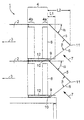
- the air intake system 1 comprises two superposed ones and equally designed air guiding or air flow channels 2, in a gas turbine, not shown flow into.
- each air duct 2 arises in Flow direction 3 an air flow to the gas turbine. Air that has been filtered beforehand is sucked in by the gas turbine.
- the filter device 4 comprises an inner fine filter 4b and an outer one connected upstream of this Coarse filter 4a.
- the filter level of the filter device 4 runs vertical and perpendicular to the plane of the drawing.
- the weather hood 5 is opposite to the horizontal one Air duct 2 arranged inclined.
- the angle of inclination is ⁇ of the weather hood 5 with respect to the air duct 2 and therefore expediently compared to the horizontal 45 °.
- Close the weather hood 5 and its opening level 6 an opening angle ⁇ of (90 ⁇ 15), so that the of the Gas turbine sucked air in the inflow direction 7 always from penetrates diagonally into the weather hood 5 below. This can the filter device 1 particularly well against weather influences to be protected.
- the air control device 9 is in the flow direction 3, 7 of the intake air in front of the coarse filter 4a and in the area of the filter device 4 near, inner opening edge 10 of the weather hood 5 arranged.
- the air guiding device 9 can be used as an air guiding wing, Air pipe or particularly advantageous as an air baffle be executed.
- the length L1 of the air guiding device lies here 9 in the longitudinal direction of the air duct 2 in the area from 15% to 30% of the length L2 of the horizontal extent of the Weather hood 5.
- L2 is also the distance between the inflow side 8 of the coarse filter 4a and that of the filter device 4 distant, outer opening edge 11 of the weather hood 5.
- the air guiding device 9 at least approximately parallel to the air duct 2 and perpendicular to the filter device 4 aligned. This removes the weather hood 5 and 12 filter beams in the form of I-beams outgoing adverse influences on the speed profile the air flow in a simple way reduced.
- the air guiding device 9 is advantageously nearby the filter device 4 and arranged inside the weather hood 5, wherein the inner opening edge 10 at least partially towered over.
- Conveniently designed as an air baffle Air guiding device 9 extends horizontally and - in the direction perpendicular to the plane of the drawing - preferably over the entire width of the air duct 2 and thus across the entire width of the filter device 4.
- Another equalization of the speed profile the air flow on the inflow side 8 of the filter device 4 can be effected in that further air guiding devices assigned to or in the air intake system be provided.
Landscapes
- Engineering & Computer Science (AREA)
- Chemical & Material Sciences (AREA)
- Combustion & Propulsion (AREA)
- Mechanical Engineering (AREA)
- General Engineering & Computer Science (AREA)
- Filtering Of Dispersed Particles In Gases (AREA)
- Cooling, Air Intake And Gas Exhaust, And Fuel Tank Arrangements In Propulsion Units (AREA)
Description
Claims (7)
- Luftansaugsystem für eine Gasturbine mit einer einer Filtereinrichtung (4) vorgeordneten geneigten Wetterhaube (5),
dadurch gekennzeichnet, dass zur Vergleichmäßigung des Geschwindigkeitsprofiles der Luftströmung der Filtereinrichtung (4) eine Luftleiteinrichtung (9) vorgeordnet ist, die im Bereich eines der Filtereinrichtung (4) nahen Öffnungsrandes (10) der Wetterhaube (5) angeordnet ist und zumindest teilweise über diesen hinausragt. - Luftansaugsystem nach Anspruch 1,
dadurch gekennzeichnet, dass die Wetterhaube (5) und deren Öffnungsebene (6) miteinander einen Winkel β von (90 ± 15)° einschließen. - Luftansaugsystem nach Anspruch 1 oder 2,
dadurch gekennzeichnet, dass die Länge (L1) der Luftleiteinrichtung (9) 15% bis 30% der Länge (L2) des Abstandes zwischen der Filtereinrichtung (4) und dem der Filtereinrichtung (4) fernen Öffnungsrand (11) der geneigten Wetterhaube (5) beträgt. - Luftansaugsystem nach einem der Ansprüche 1 bis 3,
dadurch gekennzeichnet, dass die Luftleiteinrichtung (9) als horizontal verlaufendes Luftleitblech ausgebildet ist. - Luftansaugsystem nach einem der Ansprüche 1 bis 4,
dadurch gekennzeichnet, dass die Wetterhaube (5) gegenüber einem die Filtereinrichtung (4) aufnehmenden Luftleitkanal (2) einen Neigungswinkel α von etwa 45° aufweist. - Luftansaugsystem nach einem der Ansprüche 1 bis 5,
gekennzeichnet durch zwei übereinander angeordnete und gleichermaßen ausgebildete Luftleitkanäle (2). - Gasturbine mit einem Luftansaugsystem nach einem der Ansprüche 1 bis 6.
Applications Claiming Priority (3)
| Application Number | Priority Date | Filing Date | Title |
|---|---|---|---|
| DE19716696A DE19716696C1 (de) | 1997-04-21 | 1997-04-21 | Luftansaugsystem für eine Gasturbine |
| DE19716696 | 1997-04-21 | ||
| PCT/DE1998/001000 WO1998048160A1 (de) | 1997-04-21 | 1998-04-08 | Luftansaugsystem für eine gasturbine |
Publications (2)
| Publication Number | Publication Date |
|---|---|
| EP0977940A1 EP0977940A1 (de) | 2000-02-09 |
| EP0977940B1 true EP0977940B1 (de) | 2001-09-12 |
Family
ID=7827214
Family Applications (1)
| Application Number | Title | Priority Date | Filing Date |
|---|---|---|---|
| EP98930631A Expired - Lifetime EP0977940B1 (de) | 1997-04-21 | 1998-04-08 | Luftansaugsystem für eine gasturbine |
Country Status (4)
| Country | Link |
|---|---|
| EP (1) | EP0977940B1 (de) |
| DE (2) | DE19716696C1 (de) |
| ES (1) | ES2164435T3 (de) |
| WO (1) | WO1998048160A1 (de) |
Cited By (1)
| Publication number | Priority date | Publication date | Assignee | Title |
|---|---|---|---|---|
| WO2015084983A1 (en) * | 2013-12-03 | 2015-06-11 | Bha Altair, Llc | Air intake hood for turbine inlet filter house |
Families Citing this family (10)
| Publication number | Priority date | Publication date | Assignee | Title |
|---|---|---|---|---|
| JP2003254088A (ja) * | 2002-03-05 | 2003-09-10 | Kansai Electric Power Co Inc:The | ガスタービン用吸気フィルタユニット |
| RU2289706C2 (ru) * | 2004-10-04 | 2006-12-20 | Закрытое акционерное общество "Научно-Производственная Фирма "НЕВТУРБОТЕСТ" (ЗАО "НПФ "НЕВТУРБОТЕСТ") | Комплексное воздухоподготовительное устройство газотурбинной установки |
| US7926256B2 (en) | 2008-10-27 | 2011-04-19 | General Electric Company | Inlet system for an EGR system |
| RU2414611C2 (ru) * | 2009-05-04 | 2011-03-20 | Закрытое акционерное общество "Объединенные газопромышленные технологии "Искра-Авигаз" (ЗАО "Искра-Авигаз") | Комплексное воздухоочистительное устройство |
| BR112012014146B8 (pt) | 2009-12-18 | 2022-08-30 | Camfil Ventures Ab | Instalação com entrada de ar |
| EA019164B1 (ru) * | 2010-01-18 | 2014-01-30 | Акционерное Общество "Западно-Казахстанская Машиностроительная Компания" | Воздухозаборник для газотурбинной установки |
| DE102012017918A1 (de) * | 2012-09-11 | 2014-04-03 | Balcke-Dürr GmbH | Lufteinlasssystem für eine stationäre Brennkraftmaschine, insbesondere eine stationäre Gasturbine |
| WO2014135942A1 (en) * | 2013-03-06 | 2014-09-12 | Bombardier Inc. | Apparatus for protecting aircraft components against foreign object damage |
| JP6913108B2 (ja) | 2016-04-20 | 2021-08-04 | ゼネラル・エレクトリック・カンパニイ | アクティブノイズキャンセルシステムおよび装置 |
| CN114942143B (zh) * | 2022-05-09 | 2023-08-11 | 哈尔滨城林科技股份有限公司 | 一种燃气轮机试车台进排气系统 |
Family Cites Families (4)
| Publication number | Priority date | Publication date | Assignee | Title |
|---|---|---|---|---|
| CA1015290A (en) * | 1972-12-18 | 1977-08-09 | Pall Corporation | Vortex air cleaner assembly with acoustic attenuator |
| GB1507914A (en) * | 1975-03-25 | 1978-04-19 | Mitsubishi Heavy Ind Ltd | Device for preventing foreign matters from being sucked into a gas turbine engine for an aircraft |
| DE3644986A1 (de) * | 1986-10-15 | 1988-06-30 | Schmid Rudolf Martin | Verfahren zur verminderung der staubbelastung von filtersystemen |
| US4821520A (en) * | 1988-07-22 | 1989-04-18 | Rumfield Michael A | Turbocharger protector screen |
-
1997
- 1997-04-21 DE DE19716696A patent/DE19716696C1/de not_active Expired - Fee Related
-
1998
- 1998-04-08 EP EP98930631A patent/EP0977940B1/de not_active Expired - Lifetime
- 1998-04-08 ES ES98930631T patent/ES2164435T3/es not_active Expired - Lifetime
- 1998-04-08 WO PCT/DE1998/001000 patent/WO1998048160A1/de not_active Ceased
- 1998-04-08 DE DE59801453T patent/DE59801453D1/de not_active Expired - Fee Related
Cited By (1)
| Publication number | Priority date | Publication date | Assignee | Title |
|---|---|---|---|---|
| WO2015084983A1 (en) * | 2013-12-03 | 2015-06-11 | Bha Altair, Llc | Air intake hood for turbine inlet filter house |
Also Published As
| Publication number | Publication date |
|---|---|
| DE19716696C1 (de) | 1998-07-23 |
| EP0977940A1 (de) | 2000-02-09 |
| DE59801453D1 (de) | 2001-10-18 |
| WO1998048160A1 (de) | 1998-10-29 |
| ES2164435T3 (es) | 2002-02-16 |
Similar Documents
| Publication | Publication Date | Title |
|---|---|---|
| DE60116702T2 (de) | Lufteinlass-Dämpfer-Strukturen für Turbine | |
| DE69401553T2 (de) | Statische, dynamische Gasabfuhreinrichtung | |
| CH701074B1 (de) | Gasturbineneinlass-Filtergehäuse für einen Gasturbinenmotor und Verfahren zur Verbesserung des Wirkungsgrads eines Gasturbinenmotors. | |
| DE3036633A1 (de) | Schalldaempfende ventilationsjalousie | |
| DE4241614A1 (de) | Schalldämpfer auf der Abgasseite von Turbinen | |
| EP0322433A1 (de) | Schutzanlage zur schalldämpfung von flugzeugtriebwerksgeräuschen in eingebautem zustand bei hohen gasströmen | |
| DE2539362A1 (de) | Einlasskanal | |
| DE19716696C1 (de) | Luftansaugsystem für eine Gasturbine | |
| WO2012097995A1 (de) | Fluggasturbinenschubumkehrvorrichtung | |
| DE102009043085A1 (de) | Brennkraftmaschine mit einem Abgasturbolader und einem Abgasrückführsystem | |
| DE102007014836A1 (de) | Luftfilter- und Gebläsevorrichtung für Fahrzeugbelüftungsanlagen | |
| DE19618313A1 (de) | Axialturbine eines Abgasturboladers | |
| DE102014200699A1 (de) | Niederdruck-EGR-Ventil | |
| EP0649788A1 (de) | Vorrichtung zur Abschwächung von Ansaugwirbeln an Turbinentriebwerken | |
| EP0999349A2 (de) | Axialturbine | |
| DE3136830A1 (de) | Turbolader, insbesondere fuer motorraeder | |
| DE102015216335A1 (de) | Lüfter für eine Kühleranordnung | |
| WO2002030545A1 (de) | Filteranordnung mit einem vorfilterelement | |
| WO2006099965A1 (de) | Luftansaugvorrichtung für eine brennkraftmaschine mit einsetzbarer bypassklappeneinrichtung | |
| DE102012017918A1 (de) | Lufteinlasssystem für eine stationäre Brennkraftmaschine, insbesondere eine stationäre Gasturbine | |
| DE3403886C2 (de) | Mauerkasten mit in einem Zuluftkanal angeordneten Abluftkanal zum Anschluß an das Ende eines flachen Lüftungskanals einer Dunstabzugshaube | |
| DE10355105A1 (de) | Reinigungsvorrichtung | |
| DE9316060U1 (de) | Schalldämmvorrichtung | |
| DE202021105694U1 (de) | Abdeckung für ein auf ein schräges Dach montierbares Gerät | |
| DE102018111560B4 (de) | Verdichter mit Trimmsteller und Drainageleitung und Brennkraftmaschine mit einem solchen Verdichter |
Legal Events
| Date | Code | Title | Description |
|---|---|---|---|
| PUAI | Public reference made under article 153(3) epc to a published international application that has entered the european phase |
Free format text: ORIGINAL CODE: 0009012 |
|
| 17P | Request for examination filed |
Effective date: 19991019 |
|
| AK | Designated contracting states |
Kind code of ref document: A1 Designated state(s): CH DE ES FR GB LI SE |
|
| GRAG | Despatch of communication of intention to grant |
Free format text: ORIGINAL CODE: EPIDOS AGRA |
|
| GRAG | Despatch of communication of intention to grant |
Free format text: ORIGINAL CODE: EPIDOS AGRA |
|
| GRAH | Despatch of communication of intention to grant a patent |
Free format text: ORIGINAL CODE: EPIDOS IGRA |
|
| 17Q | First examination report despatched |
Effective date: 20010305 |
|
| GRAH | Despatch of communication of intention to grant a patent |
Free format text: ORIGINAL CODE: EPIDOS IGRA |
|
| GRAA | (expected) grant |
Free format text: ORIGINAL CODE: 0009210 |
|
| AK | Designated contracting states |
Kind code of ref document: B1 Designated state(s): CH DE ES FR GB LI SE |
|
| REG | Reference to a national code |
Ref country code: CH Ref legal event code: NV Representative=s name: SIEMENS SCHWEIZ AG Ref country code: CH Ref legal event code: EP |
|
| REF | Corresponds to: |
Ref document number: 59801453 Country of ref document: DE Date of ref document: 20011018 |
|
| REG | Reference to a national code |
Ref country code: GB Ref legal event code: IF02 |
|
| GBT | Gb: translation of ep patent filed (gb section 77(6)(a)/1977) |
Effective date: 20011201 |
|
| REG | Reference to a national code |
Ref country code: ES Ref legal event code: FG2A Ref document number: 2164435 Country of ref document: ES Kind code of ref document: T3 |
|
| ET | Fr: translation filed | ||
| PGFP | Annual fee paid to national office [announced via postgrant information from national office to epo] |
Ref country code: SE Payment date: 20020423 Year of fee payment: 5 |
|
| PGFP | Annual fee paid to national office [announced via postgrant information from national office to epo] |
Ref country code: CH Payment date: 20020711 Year of fee payment: 5 |
|
| PLBE | No opposition filed within time limit |
Free format text: ORIGINAL CODE: 0009261 |
|
| STAA | Information on the status of an ep patent application or granted ep patent |
Free format text: STATUS: NO OPPOSITION FILED WITHIN TIME LIMIT |
|
| 26N | No opposition filed | ||
| PG25 | Lapsed in a contracting state [announced via postgrant information from national office to epo] |
Ref country code: SE Free format text: LAPSE BECAUSE OF NON-PAYMENT OF DUE FEES Effective date: 20030409 |
|
| PG25 | Lapsed in a contracting state [announced via postgrant information from national office to epo] |
Ref country code: LI Free format text: LAPSE BECAUSE OF NON-PAYMENT OF DUE FEES Effective date: 20030430 Ref country code: CH Free format text: LAPSE BECAUSE OF NON-PAYMENT OF DUE FEES Effective date: 20030430 |
|
| EUG | Se: european patent has lapsed | ||
| REG | Reference to a national code |
Ref country code: CH Ref legal event code: PL |
|
| PGFP | Annual fee paid to national office [announced via postgrant information from national office to epo] |
Ref country code: ES Payment date: 20080514 Year of fee payment: 11 |
|
| PGFP | Annual fee paid to national office [announced via postgrant information from national office to epo] |
Ref country code: DE Payment date: 20080620 Year of fee payment: 11 |
|
| PGFP | Annual fee paid to national office [announced via postgrant information from national office to epo] |
Ref country code: GB Payment date: 20080417 Year of fee payment: 11 |
|
| GBPC | Gb: european patent ceased through non-payment of renewal fee |
Effective date: 20090408 |
|
| REG | Reference to a national code |
Ref country code: FR Ref legal event code: ST Effective date: 20091231 |
|
| PG25 | Lapsed in a contracting state [announced via postgrant information from national office to epo] |
Ref country code: DE Free format text: LAPSE BECAUSE OF NON-PAYMENT OF DUE FEES Effective date: 20091103 |
|
| PG25 | Lapsed in a contracting state [announced via postgrant information from national office to epo] |
Ref country code: GB Free format text: LAPSE BECAUSE OF NON-PAYMENT OF DUE FEES Effective date: 20090408 Ref country code: FR Free format text: LAPSE BECAUSE OF NON-PAYMENT OF DUE FEES Effective date: 20091222 |
|
| PGFP | Annual fee paid to national office [announced via postgrant information from national office to epo] |
Ref country code: FR Payment date: 20080422 Year of fee payment: 11 |
|
| REG | Reference to a national code |
Ref country code: ES Ref legal event code: FD2A Effective date: 20090411 |
|
| PG25 | Lapsed in a contracting state [announced via postgrant information from national office to epo] |
Ref country code: ES Free format text: LAPSE BECAUSE OF NON-PAYMENT OF DUE FEES Effective date: 20090411 |