EP0977334A2 - Kabelrohr - Google Patents
Kabelrohr Download PDFInfo
- Publication number
- EP0977334A2 EP0977334A2 EP99305967A EP99305967A EP0977334A2 EP 0977334 A2 EP0977334 A2 EP 0977334A2 EP 99305967 A EP99305967 A EP 99305967A EP 99305967 A EP99305967 A EP 99305967A EP 0977334 A2 EP0977334 A2 EP 0977334A2
- Authority
- EP
- European Patent Office
- Prior art keywords
- end cap
- duct assembly
- assembly according
- collar
- sleeve
- Prior art date
- Legal status (The legal status is an assumption and is not a legal conclusion. Google has not performed a legal analysis and makes no representation as to the accuracy of the status listed.)
- Withdrawn
Links
Images
Classifications
-
- H—ELECTRICITY
- H02—GENERATION; CONVERSION OR DISTRIBUTION OF ELECTRIC POWER
- H02G—INSTALLATION OF ELECTRIC CABLES OR LINES, OR OF COMBINED OPTICAL AND ELECTRIC CABLES OR LINES
- H02G3/00—Installations of electric cables or lines or protective tubing therefor in or on buildings, equivalent structures or vehicles
- H02G3/02—Details
- H02G3/04—Protective tubing or conduits, e.g. cable ladders or cable troughs
- H02G3/0406—Details thereof
-
- H—ELECTRICITY
- H02—GENERATION; CONVERSION OR DISTRIBUTION OF ELECTRIC POWER
- H02G—INSTALLATION OF ELECTRIC CABLES OR LINES, OR OF COMBINED OPTICAL AND ELECTRIC CABLES OR LINES
- H02G3/00—Installations of electric cables or lines or protective tubing therefor in or on buildings, equivalent structures or vehicles
- H02G3/02—Details
- H02G3/04—Protective tubing or conduits, e.g. cable ladders or cable troughs
- H02G3/0437—Channels
- H02G3/045—Channels provided with perforations or slots permitting introduction or exit of wires
-
- H—ELECTRICITY
- H02—GENERATION; CONVERSION OR DISTRIBUTION OF ELECTRIC POWER
- H02G—INSTALLATION OF ELECTRIC CABLES OR LINES, OR OF COMBINED OPTICAL AND ELECTRIC CABLES OR LINES
- H02G3/00—Installations of electric cables or lines or protective tubing therefor in or on buildings, equivalent structures or vehicles
- H02G3/02—Details
- H02G3/06—Joints for connecting lengths of protective tubing or channels, to each other or to casings, e.g. to distribution boxes; Ensuring electrical continuity in the joint
- H02G3/0616—Joints for connecting tubing to casing
- H02G3/0691—Fixing tubing to casing by auxiliary means co-operating with indentations of the tubing, e.g. with tubing-convolutions
Definitions
- This invention relates to end caps for use with duct assemblies and more particularly, for use with assemblies that provide a duct extending through a wall or partition and within which may extend a pipe or cable.
- a duct assembly comprising an externally grooved, plastics sleeve and at least one sleeve end arrangement, which arrangement includes a part annular collar having an internal groove engaging portion and, engageable with said collar, an end cap, said end cap being provided with an aperture which at least partially faces in a direction away from the longitudinal axis of said end cap.
- the present invention also provides an isolated end cap and component parts thereof.
- the present invention also provides a method of installing a wall or partition traversing duct for a cable or pipe, the method comprising providing a length of externally grooved plastics sleeve in a wall or partition traversing location, mounting a part annular collar, having a groove engaging portion, on the sleeve where it emerges from one side of the wall or partition, severing the sleeve flush to said collar and mounting an annular end cap on said collar, said collar and said end cap being engageable with each other, and said end cap being provided with an aperture which at least partially faces in a direction away from the longitudinal axis of said end cap.
- the invention provides a very simple duct assembly, and method for its installation, which typically comprises only five components, namely, a sleeve and, for each end of the duct, a part annular collar, or circlip, and an end cap.
- the end cap is provided with at least one aperture suitably adapted so as to allow passage of a pipe or cable.
- a guide means associated with the aperture of the end cap there is provided a guide means.
- the guide means may project a selected distance from the periphery of the end cap and/or may be provided as a grooved/shaped region extending radially and inwardly from a rim portion of the end cap .
- Said guide means may be provided integrally or as a separate component that can be fixedly attached to the end cap.
- the end cap is circular and dome shaped.
- it may take the form of a circular member that is provided with a region that is relatively flat at the periphery and is dome shaped at a region around the centre.
- the end cap is made of plastics material by a moulding, machining or other suitable operation.
- the end cap and the part annular collar are engageable by means of a snap fit connection therebetween.
- This snap fit connection may be achieved by, for instancc, engagement between an integral, axially extending and peripherally grooved extension of said collar with an integral, internal peripheral flange providing on the end cap.
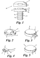
- the duct assembly A comprises a plastic sleeve 17 having grooves 15 spaced apart by radially extending circumferential projections 16.
- the assembly further comprises a part annular collar 14 with a groove 13 and flange 12 and aperture 11 for snap fit engagement with end cap 1.
- End cap 1 being provided with an aperture 3 for accommodating a cable or wire or conduit.
- the end cap provides discrete and attractive concealment of the said cable or wire or conduit.
- end cap 1 in accordance with the present invention.
- End cap 1 is provided, at its edge with a small, inwardly directed flange or shaped/grooved section 2 which defines an aperture 3.
- end cap 1 is provided with a relatively flat region 5 which extends a distance X from the end cap periphery perimeter towards the centre.
- the end cap is dome shaped at region 4. It will be appreciated that the distance X and the height of the dome region 4 can be varied according to a user's requirements.
- one of the assembly components is provided with an integral projection.
- Said integral projection extends longitudinally from the main body of the circlip, and is provided with an externally grooved portion and whose maximum diameter, adjacent said grooved portion, is slightly less than the maximum diameter of the main body. The diameter at this point is slightly less than the diameter of the aperture 3 defined by flange 2 of end cap 1. Due to the nature of the materials of end cap 1 and the circlip (typically hard but slightly resilient plastics material), the end cap 1 may be pushed into engagement with the circlip by a snap-fit connection.
- the only item seen from the exterior of the wall or partition is the external surface of the end cap which provides a neat and pleasing appearance.
- end cap 1 is provided as a dome shaped member over the entire upper region 9. Furthermore, in this embodiment there is provided an externally projecting pipe/cable guide means 6.
- the walls of the guide means being an inverted U shape in cross section. Additionally provided in an upper surface of the guide means 6 is an opening 7 which is provided to allow observation of the conduit(s) held therein.
- Figure 4 which shows an under-side view of Figure 3, the walls of guide means 6 are continuos along three sides.
- a fourth wall 8 Approximately mid-way along the length that the guide means projects from the periphery perimeter of the end cap, there is provided a fourth wall 8 so that the guide means effectively forms a hollow square for at least a part of its length.
- the conduit typically a pipe or cable is held away from a part of the wall surface.
- end cap 1 in accordance with the present invention.
- end cap 1 is dome shaped at its upper region 9 and aperture 3 is provided with an internally protruding guide means 10.
- the end cap of the present invention can be provided as dome shaped or partially dome shaped and can be provided with an internally or externally projecting guide means. The combination of which can be selected according to a user's requirements.
- the end cap of the present invention provides a component for use with duct assemblies that improves the external appearance of the assembly and concomitantly improves safety by enclosing conduits such as pipes and cables as they exit/enter walls or the like.
Landscapes
- Engineering & Computer Science (AREA)
- Architecture (AREA)
- Civil Engineering (AREA)
- Structural Engineering (AREA)
- Details Of Indoor Wiring (AREA)
- Duct Arrangements (AREA)
Applications Claiming Priority (2)
| Application Number | Priority Date | Filing Date | Title |
|---|---|---|---|
| GB9816471 | 1998-07-30 | ||
| GBGB9816471.8A GB9816471D0 (en) | 1998-07-30 | 1998-07-30 | Duct assembly |
Publications (2)
| Publication Number | Publication Date |
|---|---|
| EP0977334A2 true EP0977334A2 (de) | 2000-02-02 |
| EP0977334A3 EP0977334A3 (de) | 2000-10-25 |
Family
ID=10836341
Family Applications (1)
| Application Number | Title | Priority Date | Filing Date |
|---|---|---|---|
| EP99305967A Withdrawn EP0977334A3 (de) | 1998-07-30 | 1999-07-27 | Kabelrohr |
Country Status (2)
| Country | Link |
|---|---|
| EP (1) | EP0977334A3 (de) |
| GB (2) | GB9816471D0 (de) |
Family Cites Families (6)
| Publication number | Priority date | Publication date | Assignee | Title |
|---|---|---|---|---|
| US4809937A (en) * | 1987-09-23 | 1989-03-07 | Big Jon, Inc. | Cable penetration plug |
| DE8915213U1 (de) * | 1989-12-28 | 1990-02-08 | REHAU AG + Co, 8673 Rehau | Mauerdurchführung für Rohre, Kabel oder Leitungen |
| GB9519840D0 (en) * | 1995-09-29 | 1995-11-29 | Artform Int Ltd | Ducts |
| GB9615536D0 (en) * | 1996-07-24 | 1996-09-04 | Artform Int Ltd | Cable entry system |
| SE507032C2 (sv) * | 1996-08-29 | 1998-03-16 | Olle Waanghed | Rörgenomföringsanordning |
| GB2322924B (en) * | 1997-03-07 | 2001-08-01 | Sankey Robert David | Duct assembly |
-
1998
- 1998-07-30 GB GBGB9816471.8A patent/GB9816471D0/en not_active Ceased
-
1999
- 1999-07-26 GB GB9917388A patent/GB2340515B/en not_active Expired - Fee Related
- 1999-07-27 EP EP99305967A patent/EP0977334A3/de not_active Withdrawn
Also Published As
| Publication number | Publication date |
|---|---|
| GB2340515A (en) | 2000-02-23 |
| GB9816471D0 (en) | 1998-09-23 |
| GB9917388D0 (en) | 1999-09-22 |
| GB2340515B (en) | 2002-06-12 |
| EP0977334A3 (de) | 2000-10-25 |
Similar Documents
| Publication | Publication Date | Title |
|---|---|---|
| EP1160950B1 (de) | Kabelkanalkupplung mit Klemmhalter | |
| US5347882A (en) | Cable mounting construction | |
| US5806139A (en) | Grommet assembly | |
| EP1182091B1 (de) | Durchführungstülle | |
| CA2063056C (en) | Snap-in connector with integral spring | |
| US6220297B1 (en) | Pull-out spray head having reduced play | |
| US6194659B1 (en) | Cable entry device | |
| JPH026312Y2 (de) | ||
| US12140254B2 (en) | Adaptive retainer | |
| ITTO970003A1 (it) | Sistema per il montaggio di un gruppo cuscinetto con mozzo ruota nel montante della sospensione di un autoveicolo | |
| JP2020043675A (ja) | グロメット | |
| US5392691A (en) | Stone shield for air brake actuator with welded yoke | |
| US8282137B2 (en) | End piece for a corrugated hose and parts set containing such an end piece | |
| EP0977334A2 (de) | Kabelrohr | |
| US7614664B1 (en) | Fast-connecting joint for corrugated pipes | |
| US6353179B1 (en) | Cable entry system | |
| EP0863349B1 (de) | Baueinheit zum Herstellen einer Wanddurchführung | |
| CZ295210B6 (cs) | Teleskopická sací trubka vysavače | |
| JP2560747Y2 (ja) | コントロールケーブル | |
| EP1779033B1 (de) | Deckenbefestigung oder -abdeckung | |
| US6945515B2 (en) | Fish tape guide and method of using same | |
| JP7428077B2 (ja) | グロメット | |
| KR200360240Y1 (ko) | 벽체에 매립되어 가스관을 보호하는 슬리브. | |
| AU782900B2 (en) | Cap for protecting and anchoring electrical capacitors | |
| JP2514381Y2 (ja) | グロメット |
Legal Events
| Date | Code | Title | Description |
|---|---|---|---|
| PUAI | Public reference made under article 153(3) epc to a published international application that has entered the european phase |
Free format text: ORIGINAL CODE: 0009012 |
|
| AK | Designated contracting states |
Kind code of ref document: A2 Designated state(s): AT BE CH CY DE DK ES FI FR GB GR IE IT LI LU MC NL PT SE Kind code of ref document: A2 Designated state(s): AT BE CH CY DE DK ES FI FR GR IE IT LI LU MC NL PT SE |
|
| AX | Request for extension of the european patent |
Free format text: AL;LT;LV;MK;RO;SI |
|
| PUAL | Search report despatched |
Free format text: ORIGINAL CODE: 0009013 |
|
| AK | Designated contracting states |
Kind code of ref document: A3 Designated state(s): AT BE CH CY DE DK ES FI FR GB GR IE IT LI LU MC NL PT SE |
|
| AX | Request for extension of the european patent |
Free format text: AL;LT;LV;MK;RO;SI |
|
| 17P | Request for examination filed |
Effective date: 20010418 |
|
| AKX | Designation fees paid |
Free format text: AT BE CH CY DE DK ES FI FR GB GR IE IT LI LU MC NL PT SE |
|
| RBV | Designated contracting states (corrected) |
Designated state(s): AT BE CH CY DE DK ES FI FR GR IE IT LI LU MC NL PT SE |
|
| STAA | Information on the status of an ep patent application or granted ep patent |
Free format text: STATUS: THE APPLICATION IS DEEMED TO BE WITHDRAWN |
|
| 18D | Application deemed to be withdrawn |
Effective date: 20070201 |