EP0977158A2 - Verfahren und Vorrichtung zum Prüfen von Münzen - Google Patents
Verfahren und Vorrichtung zum Prüfen von Münzen Download PDFInfo
- Publication number
- EP0977158A2 EP0977158A2 EP19990305323 EP99305323A EP0977158A2 EP 0977158 A2 EP0977158 A2 EP 0977158A2 EP 19990305323 EP19990305323 EP 19990305323 EP 99305323 A EP99305323 A EP 99305323A EP 0977158 A2 EP0977158 A2 EP 0977158A2
- Authority
- EP
- European Patent Office
- Prior art keywords
- coin
- data
- waveform
- validator
- output
- Prior art date
- Legal status (The legal status is an assumption and is not a legal conclusion. Google has not performed a legal analysis and makes no representation as to the accuracy of the status listed.)
- Withdrawn
Links
Images
Classifications
-
- G—PHYSICS
- G07—CHECKING-DEVICES
- G07D—HANDLING OF COINS OR VALUABLE PAPERS, e.g. TESTING, SORTING BY DENOMINATIONS, COUNTING, DISPENSING, CHANGING OR DEPOSITING
- G07D5/00—Testing specially adapted to determine the identity or genuineness of coins, e.g. for segregating coins which are unacceptable or alien to a currency
- G07D5/06—Testing the hardness or elasticity
Definitions
- This invention relates to a method and an apparatus for validating coins.
- a coin validator determines the shape of at least the initial part of a vibration caused by an impact of the coin being tested, the coin validator then taking the determined shape into account in producing a signal indicating whether or not the tested coin is genuine.
- the validator can be arranged to indicate that the coin is not genuine unless the shape is determined to be appropriate.
- the closeness of the determined shape to an appropriate shape can be used as one of a number of factors taken into account in determining whether the coin is genuine, and possibly the coin denomination.
- the vibration produced by the coin impact is sensed by a piezoelectric element, and the output signal is processed to determine the shape of the initial part of the vibration. It has been found that this shape is characteristic of material properties of the coin being tested, and particularly the hardness. Depending upon the structure of the coin validator and the manner in which the impact is produced and sensed, the later part of the signal may be less representative of the coin properties and therefore it is preferable to disregard this part of the signal. For example, in particular embodiments, it has been found that although the initial part of the vibration contains information indicative of the coin hardness, the later parts of the vibration are dominated by the mechanical characteristics of the validator.
- the shape of the vibration waveform is determined on the basis of the vibration during the first millisecond after the impact, and more preferably during the first quarter of a millisecond.
- the data used to determine the shape of the vibration waveform can be derived in a number of ways.
- the waveform amplitude is sampled at predetermined intervals.
- the sampling commences when the amplitude reaches a predetermined threshold level.
- the waveform is monitored to determine the times at which predetermined amplitudes are reached. This, however, is less preferable because it has been found that the range of amplitudes varies substantially from impact to impact, so that allowing for the largest range of amplitudes would result in a loss of resolution.
- the vibration waveform is processed to determine the time and amplitude at which certain events occur, for example the times and amplitudes of the peaks and troughs in the vibration waveform.
- this could also suffer from dynamic range problems, and requires additional processing.
- the samples are weighted and summed, and preferably applied to a non-linear function. This could be performed a number of times, with the outputs of the non-linear functions also being combined in a weighted manner.
- a neural network can be trained in a per se known manner, e.g. using back propagation.
- neural networks provide a rapid method of generating an algorithm to process the data
- algorithms could obviously be developed by other methods to provide discrimination between numerical representations of the waveforms. Analysis would lead to an understanding of the relationships between the waveform and the known form of the coin giving rise to the signal.
- the waveform data could be analysed to discover deeper interrelationships. Non linearities might be accommodated by use of power laws, logarithms, trigonometrical or other functions. Regression techniques could be employed, for example, with polynomials to develop a model which ultimately discriminates the waveforms. These approaches would work, but use of a neural network is preferred because it leads to a fast and sufficiently effective result which is simple to incorporate in a product.
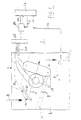
- the validator 2 comprises a test structure 4.
- This structure comprises a deck (not shown) and a lid 6 which is hingedly mounted to the deck such that the inner sides of the deck and lid are in proximity to and face each other.
- Figure 1 shows the test structure 4 as though viewed from the outer side of the lid.
- the inner side of the lid is moulded so as to form, with the deck, a narrow passageway for coins to travel edge first in the direction of arrows A.
- the moulded inner surface of the lid 6 includes a ramp 8 along which the coins roll as they are being tested.
- an energy-absorbing element 10 positioned so that coins received for testing fall on to it.
- the element 10 is preferably made of material which is harder than any of the coins intended to be tested, and serves to remove a large amount of kinetic energy from the coin as the coin hits the element.
- the energy-absorbing element may be structured and mounted as shown in EP-A-466 791.
- a wall 12 is formed on the outer side of the lid 6, and a piezoelectric element 14 is mounted on this wall.
- the vibrations caused by the coin impacting the energy-absorbing element 10 pass through the test structure 4, and in particular are carried by the lid 6 and the wall 12 to the piezoelectric element 14, which generates a signal on an output line 16.
- the coils 18 are connected via lines 20 to an interface circuit 22, which also receives signals from the piezoelectric element 14 via output line 16.
- the interface circuit 22 comprises oscillators for driving the electromagnetic coils 18, circuits for appropriately filtering and shaping the signals from lines 16 and 20 and a multiplexing circuit for delivering any one of the signals from the piezoelectric element 14 and the pairs of coils 18 to an analog-to-digital converter 24.
- a control circuit 26, including a microprocessor, has an output line 28 connected to the analog-to-digital converter 24, and is able to send pulses over the output line 28 in order to cause the analog-to-digital converter 24 to take a sample of its input signal and provide the corresponding digital output value on a data bus 30.
- the control circuit 26 can obtain digital samples from the test structure 4, and in particular from the piezoelectric element 14 and the coils 18, and can process these digital values in order to determine whether a received test item is a genuine coin or not. If the coin is not determined to be genuine, an accept/reject gate 32 will remain closed, so that the coin will be sent along the direction B to a reject path. However, if the coin is determined to be genuine, the control circuit 26 supplies an accept pulse on line 34 which causes the gate 32 to open so that the accepted coin will fall in the direction of arrow C to a coin separator (not shown), which separates coins of different denominations into different paths and directs them to respective coin stores (not shown).
- a coin separator not shown
- a single analog-to-digital converter 24 is used in a time-sharing manner for processing the signals from the coils 18 and from the piezoelectric element 14.
- a plurality of converters could be provided if desired.
- the output from the piezoelectric element 14 is processed in the manner described below in order to determine whether the received test item is of relatively soft material, indicating that it is a counterfeit. If so, the control circuits 26 will reject the test item irrespective of the signals provided by the coils 18.
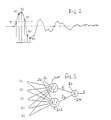
- this shows an exemplary vibration waveform produced by the piezoelectric element 14 on output line 16 following the impact of the test item with the energy-absorbing element 10.
- the control circuit 26 repeatedly checks the output of the analog-to-digital converter until the amplitude of the signal on line 16 reaches a predetermined threshold T (of, for example, 200 millivolts). (If desired, a hardware comparator can be provided for this purpose, the comparator providing a signal to the control circuit 26 when the threshold is reached.) A timer is then started. Subsequently, the timer causes the control circuit 26 to take five samples X1 to X5 of the output signal at 35 microsecond intervals.
- T of, for example, 200 millivolts
- a first process schematically illustrated by the neuron 300, takes all five values and multiplies each one by a respective predetermined weight and then sums them with a bias value B1. The sum is then applied to a non-linear function, for example a sigmoid function or a hyperbolic tangent function, to provide an output value P1.
- a non-linear function for example a sigmoid function or a hyperbolic tangent function
- a second process illustrated by neuron 302 performs a similar operation, except using different weights and a different bias value B2, to produce an output value P2.
- a third process illustrated by a summing junction 304, multiplies each of the output values P1 and P2 by a respective weight and adds these to a bias value B3 to produce an output value O.
- This output value is dependent on the shape of the initial part of the waveform shown in Figure 2, which in turn is influenced by the hardness of the test item.
- the weights and the bias values are so chosen that the control circuit 26 can determine whether the test item is relatively soft, indicating a counterfeit coin, by determining whether or not the output value O exceeds a predetermined threshold. Accordingly, the output value O is compared with this threshold in order to produce a yes/no output.
- the output value O is compared to a range of values, and the processor determines that the test item is a counterfeit in dependence upon whether or not the value lies within the range. This would for example be useful if there are counterfeit coins which have a hardness greater than that of genuine coins.
- the processing of the output signal from the element can occur before the output signals from the coils need to be processed. If the output of the piezoelectric element indicates that a counterfeit coin has been received, the processing of the output signals from the coils can be omitted.
- the signal from the piezoelectric element 14 is used (preferably together with the signals from the coils 18) to determine the denomination of a genuine coin.
- the validator can be arranged to store acceptance criteria for each of the denominations it is intended to validate. For each denomination, there may be stored criteria determining the type of signals expected to be received from the coils when testing a coin of that denomination.
- there can be acceptance criteria for the value O which criteria would vary according to denomination.
- the value O could be compared with a plurality of ranges, each associated with a different denomination.
- the weights and the bias values used in the processing illustrated in Figure 3 can be derived using an iterative training process. Conventional neural network techniques, such as back propagation, can be used. Samples of genuine and counterfeit coins would be repeatedly tested, while the weights and bias values are modified to enhance the discrimination between them, and, if desired, between coins of different denominations.
- This operation can be performed after assembly of the coin validator using a training procedure on each individual validator.
- the training procedure uses data from a plurality of reference validators, whereby the derived weights and biases will not be validator-specific, so that common values can thereafter be used in production of new validators and it is not necessary to determine individual weights and biases for each production validator.
- the output values O may however be different for different validators, in which case individual calibration of the validators may be performed by insertion of genuine coins to derive suitable acceptance criteria for the values O.
- the processing illustrated in Figure 3 can be varied considerably.
- the neurons 300 and 302 represent a hidden layer. If desired, there could be additional neurons in this layer, or one or more additional layers, or the layer can be omitted.
- the non-linear functions performed by these neurons can be omitted, or a further non-linear function can be added to the neuron 304.
- non-linear functions can be applied to the samples prior to combining them.
- other techniques can be used for processing and combining the individual values.
- An alternative embodiment might use only the starting point and two subsequent samples.
- Alternative embodiments for example one which use asynchronous sampling, may be such that the samples do not bear a consistent relationship to a known starting point, and in these embodiments it is desirable for at least three samples to be used.
- any other form of microphone could be used.
- the mechanical properties of the coin, and particularly its hardness are tested by examining the results of a coin impact.
- similar techniques could be used for examining the output of a sensor responsive to different characteristics of the coin.
- an electromagnetic sensor such as formed by a pair of the coils 18 referred to above, produces a time varying signal as the coin passes it.
- the signal could for example represent the frequency or the amplitude of the sensor output.
- a counter may be used to measure frequency, in which case the output is already digital.
- the variations in the signal correspond to variations in the position of the coin, instead of the nature of the vibrations caused by the coin impact. Nevertheless, these variations are characteristic of the coin, and it would therefore be possible to validate the coin using a technique similar to that described above, by analysing samples of the waveform to provide a value indicative of the waveform's shape. Variations in coin speed would cause the shape to expand or contract along the time axis, but this could be dealt with either by sensing coin movement and taking this into account in the processing, or by training the neural network such that speed variations have little effect on the results.
- an analog sensor output could be fed to sequentially-triggered sample and hold circuits, so as to derive a plurality of analog samples which are fed to a hardware neural network.
- coin validators any coin (whether valid or counterfeit), token, slug, washer, or other metallic object or item, and especially any metallic object or item which could be utilised by an individual in an attempt to operate a coin-operated device or system.
- a "valid coin” is considered to be an authentic coin, token, or the like, and especially an authentic coin of a monetary system or systems in which or with which a coin-operated device or system is intended to operate and of a denomination which such coin-operated device or system is intended selectively to receive and to treat as an item of value.
Landscapes
- Physics & Mathematics (AREA)
- General Physics & Mathematics (AREA)
- Testing Of Coins (AREA)
Applications Claiming Priority (2)
| Application Number | Priority Date | Filing Date | Title |
|---|---|---|---|
| GB9814937A GB2339316A (en) | 1998-07-09 | 1998-07-09 | Coin validators |
| GB9814937 | 1998-07-09 |
Publications (1)
| Publication Number | Publication Date |
|---|---|
| EP0977158A2 true EP0977158A2 (de) | 2000-02-02 |
Family
ID=10835269
Family Applications (1)
| Application Number | Title | Priority Date | Filing Date |
|---|---|---|---|
| EP19990305323 Withdrawn EP0977158A2 (de) | 1998-07-09 | 1999-07-05 | Verfahren und Vorrichtung zum Prüfen von Münzen |
Country Status (2)
| Country | Link |
|---|---|
| EP (1) | EP0977158A2 (de) |
| GB (1) | GB2339316A (de) |
Cited By (1)
| Publication number | Priority date | Publication date | Assignee | Title |
|---|---|---|---|---|
| EP1383086A1 (de) * | 2002-07-19 | 2004-01-21 | Mars, Incorporated | Münzprüfung durch Signalverarbeitung |
Families Citing this family (1)
| Publication number | Priority date | Publication date | Assignee | Title |
|---|---|---|---|---|
| GB2401704B (en) * | 2003-05-14 | 2006-01-25 | Money Controls Ltd | Coin acceptor with improved piezoelectric sensor device |
Citations (3)
| Publication number | Priority date | Publication date | Assignee | Title |
|---|---|---|---|---|
| GB2236609A (en) | 1989-10-04 | 1991-04-10 | Mars Inc | Coin validator with impact sensor |
| EP0496754A1 (de) | 1989-10-18 | 1992-08-05 | Mars Inc | Verfahren und vorrichtung zur echtheitsprüfung von geld. |
| EP0543212A1 (de) | 1991-11-19 | 1993-05-26 | National Rejectors Inc. GmbH | Münzprüfeinrichtung zur Härtebestimmung von Münzen |
Family Cites Families (2)
| Publication number | Priority date | Publication date | Assignee | Title |
|---|---|---|---|---|
| ES8703205A1 (es) * | 1985-10-16 | 1987-02-16 | Telefonica Nacional Espana Co | Procedimiento y aparato para la identificacion de monedas |
| GB2224590A (en) * | 1988-11-05 | 1990-05-09 | Plessey Co Plc | Coin validation apparatus |
-
1998
- 1998-07-09 GB GB9814937A patent/GB2339316A/en not_active Withdrawn
-
1999
- 1999-07-05 EP EP19990305323 patent/EP0977158A2/de not_active Withdrawn
Patent Citations (3)
| Publication number | Priority date | Publication date | Assignee | Title |
|---|---|---|---|---|
| GB2236609A (en) | 1989-10-04 | 1991-04-10 | Mars Inc | Coin validator with impact sensor |
| EP0496754A1 (de) | 1989-10-18 | 1992-08-05 | Mars Inc | Verfahren und vorrichtung zur echtheitsprüfung von geld. |
| EP0543212A1 (de) | 1991-11-19 | 1993-05-26 | National Rejectors Inc. GmbH | Münzprüfeinrichtung zur Härtebestimmung von Münzen |
Cited By (2)
| Publication number | Priority date | Publication date | Assignee | Title |
|---|---|---|---|---|
| EP1383086A1 (de) * | 2002-07-19 | 2004-01-21 | Mars, Incorporated | Münzprüfung durch Signalverarbeitung |
| US7025190B2 (en) | 2002-07-19 | 2006-04-11 | Mars, Incorporated | Coin validation by signal processing |
Also Published As
| Publication number | Publication date |
|---|---|
| GB9814937D0 (en) | 1998-09-09 |
| GB2339316A (en) | 2000-01-19 |
Similar Documents
| Publication | Publication Date | Title |
|---|---|---|
| US6705448B1 (en) | Method and apparatus for validating currency | |
| US4936435A (en) | Coin validating apparatus and method | |
| US5469952A (en) | Coin discrimination apparatus | |
| US5833042A (en) | Coin discriminator | |
| AU688474B2 (en) | Coin validation | |
| EP1012796B1 (de) | Verfahren und vorrichtung zum überprüfen von münzen | |
| EP0977158A2 (de) | Verfahren und Vorrichtung zum Prüfen von Münzen | |
| EP0766207B1 (de) | Verfahren und Vorrichtung zum Identifizieren von Münzen | |
| JPH04123191A (ja) | 検銭装置 | |
| US6223878B1 (en) | Method and apparatus for validating coins | |
| JP3168737B2 (ja) | 硬貨選別装置 | |
| US7025190B2 (en) | Coin validation by signal processing | |
| EP0878783B1 (de) | Münzprüfsystem | |
| CA2163869C (en) | Coin validation | |
| JP4178254B2 (ja) | 硬貨識別装置 | |
| JPH0650548B2 (ja) | 硬貨の識別装置 | |
| EP1100051A3 (de) | Münzprüfgerät | |
| Lopez-Martin et al. | Recent developments in electronic coin detectors | |
| MXPA95004935A (es) | Validacion de monedas | |
| TH12756B (th) | อุปกรณ์แยกลักษณะเหรียญ | |
| TH25712A (th) | อุปกรณ์แยกลักษณะเหรียญ |
Legal Events
| Date | Code | Title | Description |
|---|---|---|---|
| PUAI | Public reference made under article 153(3) epc to a published international application that has entered the european phase |
Free format text: ORIGINAL CODE: 0009012 |
|
| AK | Designated contracting states |
Kind code of ref document: A2 Designated state(s): AT BE CH CY DE DK ES FI FR GB GR IE IT LI LU MC NL PT SE |
|
| AX | Request for extension of the european patent |
Free format text: AL;LT;LV;MK;RO;SI |
|
| STAA | Information on the status of an ep patent application or granted ep patent |
Free format text: STATUS: THE APPLICATION HAS BEEN WITHDRAWN |
|
| 18W | Application withdrawn |
Withdrawal date: 20001004 |