EP0977048B1 - Wide multilayer insulating blankets for zero boiloff superconducting magnet - Google Patents
Wide multilayer insulating blankets for zero boiloff superconducting magnet Download PDFInfo
- Publication number
- EP0977048B1 EP0977048B1 EP99305573A EP99305573A EP0977048B1 EP 0977048 B1 EP0977048 B1 EP 0977048B1 EP 99305573 A EP99305573 A EP 99305573A EP 99305573 A EP99305573 A EP 99305573A EP 0977048 B1 EP0977048 B1 EP 0977048B1
- Authority
- EP
- European Patent Office
- Prior art keywords
- layers
- superconducting magnet
- blankets
- thermal insulation
- adjacent
- Prior art date
- Legal status (The legal status is an assumption and is not a legal conclusion. Google has not performed a legal analysis and makes no representation as to the accuracy of the status listed.)
- Expired - Lifetime
Links
- 238000009413 insulation Methods 0.000 claims description 29
- 238000002595 magnetic resonance imaging Methods 0.000 claims description 20
- 239000000463 material Substances 0.000 claims description 11
- 230000005855 radiation Effects 0.000 claims description 11
- 239000000853 adhesive Substances 0.000 claims description 9
- 230000001070 adhesive effect Effects 0.000 claims description 7
- 125000006850 spacer group Chemical group 0.000 claims description 7
- 238000012546 transfer Methods 0.000 claims description 6
- 229920000134 Metallised film Polymers 0.000 claims description 5
- 229910052782 aluminium Inorganic materials 0.000 claims description 3
- XAGFODPZIPBFFR-UHFFFAOYSA-N aluminium Chemical compound [Al] XAGFODPZIPBFFR-UHFFFAOYSA-N 0.000 claims description 3
- 238000013022 venting Methods 0.000 claims description 3
- 229920000728 polyester Polymers 0.000 claims description 2
- 239000001307 helium Substances 0.000 description 53
- 229910052734 helium Inorganic materials 0.000 description 53
- SWQJXJOGLNCZEY-UHFFFAOYSA-N helium atom Chemical compound [He] SWQJXJOGLNCZEY-UHFFFAOYSA-N 0.000 description 53
- 239000007788 liquid Substances 0.000 description 23
- 239000007789 gas Substances 0.000 description 20
- 210000001503 joint Anatomy 0.000 description 15
- 238000009434 installation Methods 0.000 description 7
- 238000009835 boiling Methods 0.000 description 5
- RYGMFSIKBFXOCR-UHFFFAOYSA-N Copper Chemical compound [Cu] RYGMFSIKBFXOCR-UHFFFAOYSA-N 0.000 description 4
- 229910052802 copper Inorganic materials 0.000 description 4
- 239000010949 copper Substances 0.000 description 4
- 238000001816 cooling Methods 0.000 description 3
- 238000005304 joining Methods 0.000 description 3
- 238000004519 manufacturing process Methods 0.000 description 3
- 230000000712 assembly Effects 0.000 description 2
- 238000000429 assembly Methods 0.000 description 2
- 229910052738 indium Inorganic materials 0.000 description 2
- APFVFJFRJDLVQX-UHFFFAOYSA-N indium atom Chemical compound [In] APFVFJFRJDLVQX-UHFFFAOYSA-N 0.000 description 2
- 238000009423 ventilation Methods 0.000 description 2
- 229920002799 BoPET Polymers 0.000 description 1
- 239000004593 Epoxy Substances 0.000 description 1
- 239000004677 Nylon Substances 0.000 description 1
- 230000006835 compression Effects 0.000 description 1
- 238000007906 compression Methods 0.000 description 1
- 239000004020 conductor Substances 0.000 description 1
- 230000008878 coupling Effects 0.000 description 1
- 238000010168 coupling process Methods 0.000 description 1
- 238000005859 coupling reaction Methods 0.000 description 1
- 230000001419 dependent effect Effects 0.000 description 1
- 230000005484 gravity Effects 0.000 description 1
- 238000003384 imaging method Methods 0.000 description 1
- 238000002955 isolation Methods 0.000 description 1
- 229910052751 metal Inorganic materials 0.000 description 1
- 239000002184 metal Substances 0.000 description 1
- 238000000034 method Methods 0.000 description 1
- 239000012811 non-conductive material Substances 0.000 description 1
- 229920001778 nylon Polymers 0.000 description 1
- 239000002985 plastic film Substances 0.000 description 1
- 229920006255 plastic film Polymers 0.000 description 1
- 238000004064 recycling Methods 0.000 description 1
- 238000009877 rendering Methods 0.000 description 1
- 238000012827 research and development Methods 0.000 description 1
- 238000004826 seaming Methods 0.000 description 1
- 238000009958 sewing Methods 0.000 description 1
- 238000003860 storage Methods 0.000 description 1
- 230000007704 transition Effects 0.000 description 1
- 238000003466 welding Methods 0.000 description 1
- 238000004804 winding Methods 0.000 description 1
Images


Classifications
-
- G—PHYSICS
- G01—MEASURING; TESTING
- G01R—MEASURING ELECTRIC VARIABLES; MEASURING MAGNETIC VARIABLES
- G01R33/00—Arrangements or instruments for measuring magnetic variables
- G01R33/20—Arrangements or instruments for measuring magnetic variables involving magnetic resonance
- G01R33/28—Details of apparatus provided for in groups G01R33/44 - G01R33/64
- G01R33/38—Systems for generation, homogenisation or stabilisation of the main or gradient magnetic field
- G01R33/381—Systems for generation, homogenisation or stabilisation of the main or gradient magnetic field using electromagnets
- G01R33/3815—Systems for generation, homogenisation or stabilisation of the main or gradient magnetic field using electromagnets with superconducting coils, e.g. power supply therefor
-
- Y—GENERAL TAGGING OF NEW TECHNOLOGICAL DEVELOPMENTS; GENERAL TAGGING OF CROSS-SECTIONAL TECHNOLOGIES SPANNING OVER SEVERAL SECTIONS OF THE IPC; TECHNICAL SUBJECTS COVERED BY FORMER USPC CROSS-REFERENCE ART COLLECTIONS [XRACs] AND DIGESTS
- Y10—TECHNICAL SUBJECTS COVERED BY FORMER USPC
- Y10S—TECHNICAL SUBJECTS COVERED BY FORMER USPC CROSS-REFERENCE ART COLLECTIONS [XRACs] AND DIGESTS
- Y10S505/00—Superconductor technology: apparatus, material, process
- Y10S505/825—Apparatus per se, device per se, or process of making or operating same
- Y10S505/888—Refrigeration
- Y10S505/892—Magnetic device cooling
Definitions
- This invention relates to thermally efficient insulating blankets for helium cooled superconducting magnet assemblies for magnetic resonance imaging (hereinafter called "MRI"), and more particularly to an improved multilayer wide blanket suitable for MRI systems utilizing a recondenser for recondensing the resultant helium gas back into liquid helium.
- MRI magnetic resonance imaging
- a superconducting magnet can be made superconducting by placing it in an extremely cold environment, such as by enclosing it in a cryostat or pressure vessel containing a cryogen such as liquid helium.
- the extreme cold provided by the boiling helium maintains current flow through the magnet coils after a power source initially connected to the coil (for a relatively short period) is disconnected due to the absence of electrical resistance in the cold magnet coils, thereby maintaining a strong magnetic field.
- Superconducting magnet assemblies find wide application in the field of MRI.
- the main superconducting magnet coils are enclosed in a cylindrically shaped cryogen pressure vessel defining an imaging bore in the central region along its axis.
- a vacuum vessel surrounds the pressure vessel and a mechanical cryocooler in the space between the two vessels provides cooling to recondense the helium gas resulting from the boiling back to liquid helium for reintroduction and reuse in the helium vessel.
- Zero boiloff magnets Superconducting magnets which recondense the helium gas back to liquid helium are often referred to as zero boiloff (ZBO) magnets.
- ZBO magnets insulation is provided between the vacuum and helium pressure vessels and also around the recondenser between the recondenser and the pressure vessel to minimize heat loss. See, for example, U.S. Patent 5,613,367, U.S. Patent 5,651,256 and U.S. Patent 4,984,605.
- US-A-4 984 605 discloses a thermal insulation applied to metal tubes, which consists of blankets of spaced layers of reflective and low conductivity material.
- US-A-5 613 367 discloses an MRI device in which superinsulation is provided in the space between a radiation shield an a vacuum vessel.
- the superinsulation is an aluminized Mylar® multi-layer insulation.
- US-A-5 651 256 discloses a thermal shield surrounding a superconductive coil, said thermal shield including a flexible layer of thermally conductive material.
- a flexible blanket of multi-layer thermal insulation having a low effective coefficient of thermal conductivity surrounds said thermal shield.
- Each layer may have two portions with overlapping, taped-together edges.
- the thermal shield may consist of discrete portions having overlapping and thermally-connected edges joined together by an epoxy film or an adhesive bond.
- High efficiency insulation is very important in such ZBO systems since the mechanical cryocooler is often taxed to its cooling capabilities and heat losses can preclude proper or efficient operation of such systems.
- such insulation should provide at the same time a thermally efficient way for the escape of trapped air or gasses in the blanket during evacuation of the superconducting magnet.
- MRI superconducting magnets are necessarily quite large to accommodate patients in the bore leading to the requirement for wide blankets to, for example, surround the pressure vessel which typically can have an outer diameter of 2 meters and a length of 2 meters.
- Sufficiently wide thermal insulating blankets are cumbersome to handle and difficult to manufacture.
- Increased thickness of the multilayer blankets is disadvantageous in superconducting MRI magnets, especially in the warm patient bore, because the double thickness must be accommodated without MLI compression in a place where space is at a premium. If 1.27cm (one-half inch) of radius can be saved in the warm bore, the resulting smaller diameter superconducting coils use less superconducting wire, saving up to 1.22km (4,000 feet) of superconducting wire.
- wide thermally insulating blankets are provided by the joining of multilayer blankets each including aluminized sheets separated by insulating layers. Alternating pairs of sheets and layers are offset from each other and a plurality of T-shaped thermally low or minimally conductive stakes prevent the layers from relative movement while minimizing heat transfer through the blankets.
- the joining of the blankets to provide wider blankets provides offset alternate joints and vent slits between adjacent aluminized layers. This minimizes heat loss while allowing the evacuation of residual gas in the insulating layers during evacuation of the vacuum vessel of the superconducting magnet.
- the remote ends of the joined blanket are provided with self adhesive aluminized strips having peel off backings for securing the remote ends to form an additional joint when the blankets are positioned around a member such as the cryogen pressure vessel of the superconducting magnet.
- Aluminized strips are applied to some adjacent sheets of aluminized layers of the abutting ends of the joined blankets.
- MRI superconducting magnet system 10 includes helium pressure vessel 4 including a liquid cryogen such as helium 46 and surrounded by vacuum vessel 2 with thermally isolating radiation shield 6 interposed between the helium vessel and the vacuum vessel.
- a cryocooler 12 (which may be a Gifford-Mahon cryocooler) extends through vacuum vessel 2 within sleeve 8, 18, 23 such that the cold end of the cryocooler may be selectively positioned within the sleeve without destroying the vacuum within vacuum vessel 2, and heat generated by motor 9 of the cryocooler is outside the vacuum vessel.
- Cryocooler 12 is installed in the cryocooler sleeve assembly 8, 18, 23 with matching transition flange 21 and secured with bolts 82 and associated washers (not shown).
- First stage heat station 16 of cryocooler 12 contacts copper first stage thermal sleeve or heat sink 18 which is thermally connected through braided copper flexible thermal couplings 22 and 24 and copper thermal blocks 26 and 28 on isolating radiation shield 6 to cool the radiation shield to a temperature of approximately 60K providing active thermal isolation between helium vessel 4 and vacuum vessel 2.
- second stage heat station 30 of cryocooler 12 contacts indium gasket 29 to efficiently provide a temperature of 4 K to heat sink 11 positioned on the opposite side of the indium gasket.
- helium recondensing chamber 38 made of high thermal conductivity material such as copper, which includes a plurality of substantially parallel heat transfer plates or surfaces 42 in thermal contact with heat sink 11 and forming passages between the surfaces of the plates for helium gas flow from helium pressure vessel 4.
- Helium gas 40 forms above liquid helium surface level 44 of liquid helium supply 46 through the boiling of the liquid helium in providing cryogenic temperatures to MRI magnet system 10.
- Helium gas 40 passes through helium gas passage 50 to the interior of the upper portion 41 of helium recondensing chamber or canister 38. Cooled helium gas 40 passing between the cooled heat transfer plates 40 recondenses into liquid helium to collect in bottom region 48 of helium recondensing chamber 38. The recondensed liquid helium then flows by gravity through helium return line 54 back to liquid helium supply 46, it being noted that helium recondensing chamber 38 is positioned higher than liquid helium passageway 58 in helium vessel 4.
- liquid helium 46 cools superconducting magnet coil assembly (shown generally as 60) to a superconducting temperature with the cooling indicated generally by arrow 62 in the manner well known in the MRI art, resulting in boiling of helium liquid 46 and production of helium gas 40 above helium surface level 44.
- helium gas 40 instead of being vented to the surrounding atmosphere 37 as is common in many MRI equipments is recondensed back to liquid helium and returned to liquid helium supply 46 as liquid helium in the manner described.
- Multilayer thermal insulation blankets 34 and 36 are provided in the space between radiation shield 6 and vacuum vessel 2 and in the space between the radiation shield and helium vessel 4 to further thermally isolate helium vessel 4 from vacuum vessel 2.
- Insulation blanket 35 is provided between recondensing chamber 38 and helium vessel 4 to thermally isolate the recondensing chamber 38, particularly during removal and servicing of cryocooler 12 which warms up cryocooler sleeve 13.
- Superinsulation 34 and 36 are wide aluminized multi-layer insulation blankets as described below.
- thermal insulation blankets 84 and 86 include a plurality of sheets or layers (20 or more) of low emissivity 25 gauge thin aluminized Mylar® or aluminum thermally reflective sheets such as 60, 73, 74, 76, 77, 79, 80, 88 and 90 separated by low conductivity material spacer sheets such as 62 of spun-bonded polyester which is not bonded to the aluminized Mylar® or aluminum sheets potentially enabling their separate and relative motion.
- they are held together by the plurality of stakes 69 of nonconductive material such as Nylon to prevent such relative motion of the layers during handling.
- Stakes 69 may be similar to the "T" bar stakes used in the clothing industry.
- Other methods of holding the blanket together to prevent slipping or movement of the layers 60 and 62 during handling and installation include sewing with PET (polyethyleneterpenthalate) thread and ultrasonic welding.
- adjacent top layer reflective sheets 60 meet at joint 70.
- the next lower layer of adjacent reflective sheets 73 and 74 and the separating low conductivity spacer sheets 71 are offset such that joint 75 is offset from joint 70.
- the next lower layer of reflective sheets 76 and 77 meet at joint 78 which is offset from joint 75 and in line with joint 70.
- the remainder of the joints of succeeding layers of reflective sheets such as 79 and 80 meet at joints such as 81 with the successive joints of the reflective sheets forming the insulating blankets interleaved and overlapping in an offset arrangement in which the joints of adjacent reflective sheets are not positioned adjacent to each other and are non-overlapping. This offset is shown by way of an enlarged top view in FIG.
- one or more venting slits or apertures 61 in reflective sheets 60 extend substantially parallel to joint 70 to allow the escape or evacuation of any residual air or gas trapped within spacer sheets 62 when vacuum vessel 2 (see FIG. 1) is evacuated prior to commencing superconducting operation of superconduting magnet system 10.
- Similar ventilation slits 61 are provided in reflective sheets such as 73, 74; 76, 77; 79, 80; and 88, 90 (see FIG. 2) such that the offsetting of the successive reflective sheets offsets the ventilation slits in the same manner as joints such as 70 and 75 are offset.
- This provides a tortuous indirect path for the escape of entrapped gas but avoids a direct thermal opening through multilayer blankets 84 and 86. Gas may also escape through the joints such as 70 and 75 between adjacent layers of blankets 84 and 86, it being appreciated that the openings are shown oversized in the Figures for purposes of explanation.
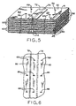
- blankets 84 and 86 are joined together to form a wider blanket for a particular installation, and the combined blankets wrapped around the appropriate superconducting magnet 10 components (such as shown by blankets 34 and 36 in FIG. 1 to surround thermal shield 6 and pressure vessel 10) their remote ends are joined by the butt joint and tape tabs as shown by FIGs. 3, 4 and 5.
- FIGs. 3, 4 and 5 show the joint at remote ends of multi-layer insulating blankets 84 and 86.
- blankets 84 and 86 are butted together as closely as possible with joint or seam 70 spacing being exaggerated in FIGs. 3 and 5.
- a plurality of adjoining ends of low emissivity reflective aluminized sheets (all of which are indicated as 60 in FIG. 5) are joined together by overlapping tape tabs or strips 72 which extend over the seam region of adjacent reflective sheets 60. It is to be noted that a plurality, but only some, of adjacent sheets 60 are secured together in FIG. 5 by strips 72. It may be desirable for some installations to join most or even every adjacent pair of aluminized reflective sheets 60 with tape tabs 72 in order to form an enclosure with seams that will be most effective in minimizing heat transfer from vacuum vessel 2 to radiation shield 6 (see FIG. 1).
- tape tab 72 includes a suitable adhesive 80, 82 on one side of double aluminized Mylar® tape 74 protected by peel-off backing 76, 78 which extends from center 79 of the adhesive 80, 82 side of the tab to the edges of the tape to enable selective removal of the tabs.
- peel-off backing 76, 78 which extends from center 79 of the adhesive 80, 82 side of the tab to the edges of the tape to enable selective removal of the tabs.
- This enables one half of the peel-off backing to be removed or exposed, exposing adhesive 80 for application to aluminized sheets 60 of multilayer blanket 84 after which the remainder of peel-off backings 78 are sequentially removed to expose the rest of adhesive 82 in order to secure tape or strip74 to the adjacent aluminized sheets of blanket 86.
- Tabs 72 can be provided on any number of aluminized sheets 60 to ensure the required degree of thermal insulation and blanket structural integrity. Blankets such as 84 with preinstalled tape tabs 72 over one or more remote edges will greatly increase the speed and ease in which adjacent blankets such as 86 can be joined and installed to provide a low heat leak seal. This is particularly applicable for joining the remote ends of multi-layer blankets already joined as described above in regard to FIG. 2 and where the remote joint is accomplished after the mutlilayer blankets are installed in magnet system 10 such as insulating blankets 34 and 36 of FIG. 1.
- Multilayer insulation blankets such as 84 and 86 joined as described above provide effective insulation against heat leak between two surfaces at different temperatures such as radiation shield 6 or pressure vessel 4 and vacuum vessel 2 (see FIG. 1) and also provide escape paths for any entrapped gas in the insulating blankets during evacuation of the vacuum vessel and the rendering of superconducting magnet 10 superconducting.
- Each low emissivity layer 60 acts as an uncooled radiation shield, the efficiency of which is proportional to the surface emissivity.
- Low conductivity spacer 62 minimizes contact between adjacent layers. Since each layer effectively operates at a different temperature this minimizes conduction heat transfer.
- the high vacuum within vacuum vessel 2 minimizes conduction of heat through any residual gas between layers 60 and tape tab 72 effectively closes the seam between blankets 84 and 86 since even very small seams or cracks can cause heat leakage which can easily surpass the total heat transferred through the main blanket surface area if such cracks or seams are not properly closed.
- Self-adhesive tab 72 provides effective closure for superconducting magnet thermal insulation blankets without the tedious and time consuming task presently encountered with present closing arrangements, particularly when seaming is accomplished during superconducting magnet 10 assembly or installation.
- Tape tabs 72 are approximately 5.1cm (two inches) wide and stakes 69 are positioned approximately 30.4cm (12 inches) apart to provide room to manipulate and join adjacent sheets 60.
- FIG. 5 illustrates the use of a plurality of aluminized tape tabs 72 with the tape tabs overlying a single surface of adjacent aluminized sheet 60 while FIG. 3 illustrates different positioning of the tape tabs relative to adjacent aluminized sheets.
- tape tab 63 is positioned on the bottom surface of adjacent aluminized reflective sheets 60 while tape tabs 65 and 67 overly both the top and bottom surfaces of adjacent reflective sheets 60.
- Tape tabs 57 and 59 similar to tape tabs 65 and 67, overly both the top and bottom of adjacent reflective sheets 60.
- both of tabs 57 and 59 are shown as initially secured to blanket end 66 to be subsequently secured to adjacent blanket end 68, while in the case of tape tabs 65 and 67 tape tab 65 is initially secured to blanket end 66 while tape tab 67 is initially secured to blanket end 68 to provide a finished joint 57, 59 which is essentially the same as finished joint 65, 67.
- the initial securing of a tape tab can thus be on either insulating blanket end to be joined or some tape tabs initially on both insulating blankets. Since the alternating reflective layers 60 and insulating layers 62 are not bonded together, they are free to be moved and separated in the region between stakes 69.
- the reflective and insulating layers 60, 62 above the tab being secured can be readily pushed aside during the securing of the tape tab to the adjacent reflective layer.
- the initial positions of tape tabs 72 relative to the reflective layers 60 to which they are secured are shown in FIG. 3 without pushing adjacent layers aside.
- the present invention thus provides insulating blankets wider than those commercially manufactured and available and which are suitable for use in superconducting magnets which require such wider blankets, and in particular in zero boiloff magnets which are very sensitive to residual heat leak and in which the recondensing system may be incapable of practical or efficient operation in the presence of heat leaks.
- the present invention provides a quick, inexpensive and simple arrangement to thermally seal multilayer blanket seams efficiently while at the same time providing an entrapped gas escape path.
Landscapes
- Physics & Mathematics (AREA)
- Electromagnetism (AREA)
- Condensed Matter Physics & Semiconductors (AREA)
- General Physics & Mathematics (AREA)
- Magnetic Resonance Imaging Apparatus (AREA)
- Containers, Films, And Cooling For Superconductive Devices (AREA)
Applications Claiming Priority (2)
| Application Number | Priority Date | Filing Date | Title |
|---|---|---|---|
| US127499 | 1998-07-31 | ||
| US09/127,499 US6038867A (en) | 1998-07-31 | 1998-07-31 | Wide multilayer insulating blankets for zero boiloff superconducting magnet |
Publications (3)
| Publication Number | Publication Date |
|---|---|
| EP0977048A2 EP0977048A2 (en) | 2000-02-02 |
| EP0977048A3 EP0977048A3 (en) | 2002-04-03 |
| EP0977048B1 true EP0977048B1 (en) | 2005-12-28 |
Family
ID=22430465
Family Applications (1)
| Application Number | Title | Priority Date | Filing Date |
|---|---|---|---|
| EP99305573A Expired - Lifetime EP0977048B1 (en) | 1998-07-31 | 1999-07-14 | Wide multilayer insulating blankets for zero boiloff superconducting magnet |
Country Status (4)
| Country | Link |
|---|---|
| US (1) | US6038867A (enExample) |
| EP (1) | EP0977048B1 (enExample) |
| JP (1) | JP4374097B2 (enExample) |
| DE (1) | DE69929122D1 (enExample) |
Cited By (1)
| Publication number | Priority date | Publication date | Assignee | Title |
|---|---|---|---|---|
| US9389290B2 (en) | 2011-06-13 | 2016-07-12 | General Electric Company | System and method for insulating a cryogen vessel |
Families Citing this family (18)
| Publication number | Priority date | Publication date | Assignee | Title |
|---|---|---|---|---|
| AT4606U1 (de) * | 2000-06-09 | 2001-09-25 | Mi Developments Austria Ag & C | Speicherbehälter für kryogenen treibstoff |
| US6438966B1 (en) * | 2001-06-13 | 2002-08-27 | Applied Superconetics, Inc. | Cryocooler interface sleeve |
| EP1279886A3 (en) * | 2001-07-26 | 2005-12-14 | Applied Superconetics, Inc. | Cryocooler interface sleeve for a superconducting magnet and method of use |
| US7037083B2 (en) | 2003-01-08 | 2006-05-02 | Brooks Automation, Inc. | Radiation shielding coating |
| US6923009B2 (en) * | 2003-07-03 | 2005-08-02 | Ge Medical Systems Global Technology, Llc | Pre-cooler for reducing cryogen consumption |
| US7318318B2 (en) * | 2004-03-13 | 2008-01-15 | Bruker Biospin Gmbh | Superconducting magnet system with refrigerator |
| US7263841B1 (en) * | 2004-03-19 | 2007-09-04 | Praxair Technology, Inc. | Superconducting magnet system with supplementary heat pipe refrigeration |
| DE102004037173B3 (de) * | 2004-07-30 | 2005-12-15 | Bruker Biospin Ag | Vorrichtung zur kryogenverlustfreien Kühlung einer Kryostatanordnung |
| FR2876437B1 (fr) * | 2004-10-08 | 2007-01-19 | Cryospace L Air Liquide Aerosp | Dispositif d'isolation cryogenique, procede de mise en oeuvre et utilisation d'un tel dispositif d'isolation, et lanceur equipe d'un tel dispositif d'isolation |
| JP2007194258A (ja) * | 2006-01-17 | 2007-08-02 | Hitachi Ltd | 超伝導磁石装置 |
| US7823394B2 (en) * | 2007-11-02 | 2010-11-02 | Reflect Scientific, Inc. | Thermal insulation technique for ultra low temperature cryogenic processor |
| US8188742B2 (en) * | 2009-07-31 | 2012-05-29 | General Electric Company | System and method for thermo-electric cooling of RF coils in an MR imaging system |
| US8973378B2 (en) * | 2010-05-06 | 2015-03-10 | General Electric Company | System and method for removing heat generated by a heat sink of magnetic resonance imaging system |
| DE102012209754B4 (de) * | 2012-06-12 | 2016-09-22 | Siemens Healthcare Gmbh | Spuleneinrichtung für einen Kernspintomographen |
| CN105745554B (zh) * | 2013-11-22 | 2020-05-22 | 皇家飞利浦有限公司 | 对动态汽化减少改进的低温容器、超导磁体和mr检查系统 |
| US10185003B2 (en) * | 2014-11-18 | 2019-01-22 | General Electric Company | System and method for enhancing thermal reflectivity of a cryogenic component |
| JP6602716B2 (ja) * | 2016-03-30 | 2019-11-06 | ジャパンスーパーコンダクタテクノロジー株式会社 | 超電導マグネット装置 |
| JP6546115B2 (ja) * | 2016-03-30 | 2019-07-17 | ジャパンスーパーコンダクタテクノロジー株式会社 | 超電導マグネット装置 |
Family Cites Families (18)
| Publication number | Priority date | Publication date | Assignee | Title |
|---|---|---|---|---|
| US3130561A (en) * | 1961-06-30 | 1964-04-28 | Nat Res Corp | Insulation device |
| US3139206A (en) * | 1961-11-20 | 1964-06-30 | Union Carbide Corp | Thermal insulation |
| DE2233332B2 (de) * | 1972-07-06 | 1974-12-19 | Vki-Rheinhold U. Mahla Ag, 6800 Mannheim | Isolierung für Flüssiggasbehälter mit Isolierplatten aus Kunststoff |
| US3993213A (en) * | 1975-09-04 | 1976-11-23 | Mcdonnell Douglas Corporation | Thermally insulated cryogenic container |
| US4055268A (en) * | 1975-11-18 | 1977-10-25 | Union Carbide Corporation | Cryogenic storage container |
| JPS5684190U (enExample) * | 1979-12-03 | 1981-07-07 | ||
| JPS5715192A (en) * | 1980-07-02 | 1982-01-26 | Nippon Oxygen Co Ltd | Heat insulation pipings for high temperature and high pressure |
| DE3803112A1 (de) * | 1988-02-03 | 1989-08-17 | Kabelmetal Electro Gmbh | Leitungsrohr zum transport von tiefgekuehlten medien |
| JPH024097U (enExample) * | 1988-06-21 | 1990-01-11 | ||
| JPH0366997A (ja) * | 1989-07-31 | 1991-03-22 | Kansai Electric Power Co Inc:The | 多層断熱材 |
| JPH03282097A (ja) * | 1990-03-28 | 1991-12-12 | Hitachi Ltd | 積層断熱材 |
| JPH04116907A (ja) * | 1990-09-07 | 1992-04-17 | Toshiba Corp | 超電導冷却装置 |
| JPH0630140U (ja) * | 1992-09-11 | 1994-04-19 | 古河電気工業株式会社 | 断熱粘着シート |
| JPH07280170A (ja) * | 1994-04-12 | 1995-10-27 | Kubota Corp | 真空断熱体の充填材の充填構造 |
| JPH08296787A (ja) * | 1995-04-26 | 1996-11-12 | Matsushita Electric Works Ltd | 防音カバー |
| JPH09109323A (ja) * | 1995-10-18 | 1997-04-28 | Kanegafuchi Chem Ind Co Ltd | 積層断熱材及びその製造方法 |
| US5613367A (en) * | 1995-12-28 | 1997-03-25 | General Electric Company | Cryogen recondensing superconducting magnet |
| US5651256A (en) * | 1996-05-31 | 1997-07-29 | General Electric Company | Superconductive magnet having a thermal shield |
-
1998
- 1998-07-31 US US09/127,499 patent/US6038867A/en not_active Expired - Lifetime
-
1999
- 1999-07-14 DE DE69929122T patent/DE69929122D1/de not_active Expired - Lifetime
- 1999-07-14 EP EP99305573A patent/EP0977048B1/en not_active Expired - Lifetime
- 1999-07-30 JP JP21625599A patent/JP4374097B2/ja not_active Expired - Fee Related
Cited By (1)
| Publication number | Priority date | Publication date | Assignee | Title |
|---|---|---|---|---|
| US9389290B2 (en) | 2011-06-13 | 2016-07-12 | General Electric Company | System and method for insulating a cryogen vessel |
Also Published As
| Publication number | Publication date |
|---|---|
| JP4374097B2 (ja) | 2009-12-02 |
| US6038867A (en) | 2000-03-21 |
| DE69929122D1 (de) | 2006-02-02 |
| JP2000152922A (ja) | 2000-06-06 |
| EP0977048A2 (en) | 2000-02-02 |
| EP0977048A3 (en) | 2002-04-03 |
Similar Documents
| Publication | Publication Date | Title |
|---|---|---|
| EP0977048B1 (en) | Wide multilayer insulating blankets for zero boiloff superconducting magnet | |
| US9212782B2 (en) | Cryostat radiation shield with joining conduit supplied with vented cryogen gas | |
| JP4468388B2 (ja) | 磁場発生器 | |
| CN100580824C (zh) | 磁共振组件和超导磁体系统 | |
| US7053740B1 (en) | Low field loss cold mass structure for superconducting magnets | |
| US8354591B2 (en) | Superconducting cable | |
| US6289681B1 (en) | Superconducting magnet split cryostat interconnect assembly | |
| US4694663A (en) | Low cost intermediate radiation shield for a magnet cryostat | |
| US5222366A (en) | Thermal busbar assembly in a cryostat dual penetration for refrigerated superconductive magnets | |
| US5570723A (en) | Support system and method for jacketed multiple cryogenic pipes for cyrogenic fluid transfer | |
| US6147579A (en) | Superconducting magnet non-uniform thermal insulation blankets | |
| US5224832A (en) | Method of fabricating a multilayer insulation blanket | |
| JP2014059022A (ja) | 真空断熱低温機器における断熱支持スペーサ | |
| US11199600B2 (en) | Superconducting magnet with cold head thermal path cooled by heat exchanger | |
| JPH0429376B2 (enExample) | ||
| CN102809240A (zh) | 用于减小低温恒温器热负荷的穿透管组件 | |
| JP4494767B2 (ja) | 超電導コイル用電流リード | |
| JP7477959B2 (ja) | 超電導コイル装置、および超電導コイルの電流リード構造 | |
| JPH01312299A (ja) | トランスファーチューブ | |
| JP4517879B2 (ja) | 超電導ケーブル | |
| JP6761423B2 (ja) | 極低温構成要素の熱反射率を高めるためのシステムおよび方法 | |
| Gonczy et al. | A blanket design, apparatus, and fabrication techniques for the mass production of multilayer insulation blankets for the superconducting super collider | |
| JPH08250324A (ja) | 超電導磁石 | |
| JPH01312298A (ja) | 高断熱配管 | |
| JPH01235314A (ja) | 超伝導電磁石 |
Legal Events
| Date | Code | Title | Description |
|---|---|---|---|
| PUAI | Public reference made under article 153(3) epc to a published international application that has entered the european phase |
Free format text: ORIGINAL CODE: 0009012 |
|
| AK | Designated contracting states |
Kind code of ref document: A2 Designated state(s): AT BE CH CY DE DK ES FI FR GB GR IE IT LI LU MC NL PT SE Kind code of ref document: A2 Designated state(s): DE FR NL |
|
| AX | Request for extension of the european patent |
Free format text: AL;LT;LV;MK;RO;SI |
|
| PUAL | Search report despatched |
Free format text: ORIGINAL CODE: 0009013 |
|
| AK | Designated contracting states |
Kind code of ref document: A3 Designated state(s): AT BE CH CY DE DK ES FI FR GB GR IE IT LI LU MC NL PT SE |
|
| AX | Request for extension of the european patent |
Free format text: AL;LT;LV;MK;RO;SI |
|
| RIC1 | Information provided on ipc code assigned before grant |
Free format text: 7G 01R 33/3815 A, 7F 17C 13/00 B |
|
| 17P | Request for examination filed |
Effective date: 20021004 |
|
| AKX | Designation fees paid |
Free format text: DE FR NL |
|
| 17Q | First examination report despatched |
Effective date: 20041005 |
|
| GRAP | Despatch of communication of intention to grant a patent |
Free format text: ORIGINAL CODE: EPIDOSNIGR1 |
|
| GRAS | Grant fee paid |
Free format text: ORIGINAL CODE: EPIDOSNIGR3 |
|
| GRAA | (expected) grant |
Free format text: ORIGINAL CODE: 0009210 |
|
| AK | Designated contracting states |
Kind code of ref document: B1 Designated state(s): DE FR NL |
|
| REF | Corresponds to: |
Ref document number: 69929122 Country of ref document: DE Date of ref document: 20060202 Kind code of ref document: P |
|
| PG25 | Lapsed in a contracting state [announced via postgrant information from national office to epo] |
Ref country code: DE Free format text: LAPSE BECAUSE OF FAILURE TO SUBMIT A TRANSLATION OF THE DESCRIPTION OR TO PAY THE FEE WITHIN THE PRESCRIBED TIME-LIMIT Effective date: 20060329 |
|
| PLBE | No opposition filed within time limit |
Free format text: ORIGINAL CODE: 0009261 |
|
| STAA | Information on the status of an ep patent application or granted ep patent |
Free format text: STATUS: NO OPPOSITION FILED WITHIN TIME LIMIT |
|
| 26N | No opposition filed |
Effective date: 20060929 |
|
| PG25 | Lapsed in a contracting state [announced via postgrant information from national office to epo] |
Ref country code: FR Free format text: LAPSE BECAUSE OF FAILURE TO SUBMIT A TRANSLATION OF THE DESCRIPTION OR TO PAY THE FEE WITHIN THE PRESCRIBED TIME-LIMIT Effective date: 20070216 |
|
| PG25 | Lapsed in a contracting state [announced via postgrant information from national office to epo] |
Ref country code: FR Free format text: LAPSE BECAUSE OF FAILURE TO SUBMIT A TRANSLATION OF THE DESCRIPTION OR TO PAY THE FEE WITHIN THE PRESCRIBED TIME-LIMIT Effective date: 20051228 |
|
| PGFP | Annual fee paid to national office [announced via postgrant information from national office to epo] |
Ref country code: NL Payment date: 20160726 Year of fee payment: 18 |
|
| REG | Reference to a national code |
Ref country code: NL Ref legal event code: MM Effective date: 20170801 |
|
| PG25 | Lapsed in a contracting state [announced via postgrant information from national office to epo] |
Ref country code: NL Free format text: LAPSE BECAUSE OF NON-PAYMENT OF DUE FEES Effective date: 20170801 |