EP0976471A2 - Rotative forming machine - Google Patents
Rotative forming machine Download PDFInfo
- Publication number
- EP0976471A2 EP0976471A2 EP99113299A EP99113299A EP0976471A2 EP 0976471 A2 EP0976471 A2 EP 0976471A2 EP 99113299 A EP99113299 A EP 99113299A EP 99113299 A EP99113299 A EP 99113299A EP 0976471 A2 EP0976471 A2 EP 0976471A2
- Authority
- EP
- European Patent Office
- Prior art keywords
- workpiece
- forming machine
- machine according
- stamp
- rotary forming
- Prior art date
- Legal status (The legal status is an assumption and is not a legal conclusion. Google has not performed a legal analysis and makes no representation as to the accuracy of the status listed.)
- Withdrawn
Links
Images


Classifications
-
- B—PERFORMING OPERATIONS; TRANSPORTING
- B21—MECHANICAL METAL-WORKING WITHOUT ESSENTIALLY REMOVING MATERIAL; PUNCHING METAL
- B21D—WORKING OR PROCESSING OF SHEET METAL OR METAL TUBES, RODS OR PROFILES WITHOUT ESSENTIALLY REMOVING MATERIAL; PUNCHING METAL
- B21D28/00—Shaping by press-cutting; Perforating
- B21D28/02—Punching blanks or articles with or without obtaining scrap; Notching
- B21D28/12—Punching using rotatable carriers
Definitions
- the stamp 8 experiences a tilting movement upon penetration into the workpiece 11 and while it is being guided out of it.
- the angle of a flank 34 of the punch adjoining the cutting edge 28 to the workpiece 11 changes. This applies both to a loop-shaped movement of the cutting edge and the point P 0 , and to a deformed cycloid movement, in which the loop region becomes a straight piece 35 is degenerate or deformed.
Landscapes
- Engineering & Computer Science (AREA)
- Mechanical Engineering (AREA)
- Shaping Metal By Deep-Drawing, Or The Like (AREA)
- Perforating, Stamping-Out Or Severing By Means Other Than Cutting (AREA)
- Forging (AREA)
Abstract
Description
Die Erfindung betrifft eine Rotationsumformmaschine, insbesondere eine Stanze mit einem Rotationsstanzwerkzeug.The invention relates to a rotary forming machine, in particular a punch with a rotary punch tool.
Bei der Umformung von Bändern oder Blechen, bspw. zum Ausstanzen von Löchern, zum Einbringen von Vertiefungen, zum Freischneiden von Laschen in der Ebene des Blechs und/oder zum Freischneiden und Herausbiegen von einzelnen Blechabschnitten aus der Ebene des übrigen Blechs, können Rotationsstanzwerkzeuge dienen, die im Gegensatz zu Pressen mit hin- und hergehend angetriebenen Werkzeughälften ein kontinuierliches Arbeiten ermöglichen. Eine solche Umformeinrichtung ist bspw. aus der EP 0680793 A1 bekannt. Zu der Einrichtung gehören zwei Walzen, von denen eine an ihrem Umfang mit Vertiefungen versehen ist und eine Matrize bildet. Die andere Walze ist an ihrem Umfang mit leistenartigen Vorsprüngen versehen, die zu den Ausnehmungen der vorgenannten Walzen komplementär ausgebildet sind; sie bildet somit eine Patrize. When forming strips or sheets, e.g. for punching holes, for making recesses, for cutting tabs in the plane of the Sheet metal and / or for cutting and bending out individual sheet metal sections from the level of the rest Sheet metal, rotary punching tools can be used in the Contrary to presses with reciprocating driven Tool halves enable continuous work. Such a forming device is, for example, from the EP 0680793 A1 known. The facility includes two Rollers, one of which is recessed on its circumference is provided and forms a matrix. The other roller is provided with strip-like projections on its circumference, to the recesses of the aforementioned rollers are complementary; it therefore forms one Patrix.
Die in die Ausnehmungen der einen Walze greifenden Vorsprünge der anderen Walze, führen infolge der Rotationsbewegung der Walze in Bezug auf die Ausnehmungen, in die sie greifen, eine Schwenkbewegung aus. Diese Schwenkbewegung führt zu sich ändernden Eingriffsverhältnissen, während der Eingriffsphase von Vorsprung und Ausnehmung. Insbesondere beim Stanzen von Löchern kann dies zu Verschleißerscheinungen an den Flanken der Stempel führen.Those that engage in the recesses of one roller Projections of the other roller result from the rotational movement the roller with respect to the recesses, in which they grab a swivel motion. This swivel movement leads to changing engagement conditions, during the engagement phase of the projection and recess. This can lead to signs of wear, particularly when punching holes lead on the flanks of the stamp.
Mit der US-PS 5040397 wird sich dieses Problems angenommen. Zum Ausstanzen einer Reihe von Löchern in einem durchlaufenden Blechband sind zwei Walzen vorgesehen, die sich parallel zu ihrer jeweiligen Drehachse erstreckende rinnenförmige Ausnehmungen aufweisen. In den Ausnehmungen sitzen bewegliche Werkzeugteile, die um eine von der rinnenförmigen Ausnehmung bestimmte Achse schwenkbar sind. Die Werkzeugteile weisen eine nach außen weisende Planfläche auf, an der ein Stempel oder eine zu dem Stempel passende Ausnehmung ausgebildet ist. Die Werkzeugteile sind endseitig mit Zapfen versehen, die in einer entsprechend ausgebildeten ortsfesten Kurvenbahn laufen. Diese führt das Werkzeugteil bei Drehbewegung der Walze so, dass sich die räumliche Orientierung des Stempels bzw. der Ausnehmung wenigstens dann nicht ändert, wenn dieser mit dem Werkstück in Eingriff ist.With the US PS 5040397 this problem is addressed accepted. For punching out a series of holes in a continuous sheet metal strip, two rollers are provided, which are parallel to their respective axes of rotation have extending groove-shaped recesses. In the Recesses sit movable tool parts around one axis determined by the groove-shaped recess are pivotable. The tool parts face one to the outside facing flat surface on which a stamp or a the recess matching the stamp is formed. The Tool parts are provided at the ends with pins which in an appropriately trained fixed cam track to run. This guides the tool part when the Roll so that the spatial orientation of the stamp or at least does not change the recess, when it is engaged with the workpiece.
Es ergeben sich hier relativ aufwendige Werkzeuge.This results in relatively complex tools.
Davon ausgehend ist es Aufgabe der Erfindung, eine Rotationsumformmaschine zu schaffen, die eine einfache Grundstruktur aufweist und bei der Verschleißerscheinungen an den Werkzeugen reduziert sind.Based on this, it is an object of the invention to Rotary forming machine to create a simple Has basic structure and with the signs of wear on the tools are reduced.
Diese Aufgabe wird mit der Rotationsumformmaschine
gelöst, die die Merkmale des Patentanspruchs 1 aufweist.This task is done with the rotary forming machine
solved, which has the features of
Die erfindungsgemäße Rotationsumformmaschine weist ein Werkzeug auf, zu dem zwei Walzen mit entsprechenden Stempeln und Ausnehmungen oder allgemein Patrizen und Matrizen gehören. Wenigstens eine, vorzugsweise beide der Walzen sind von einer Antriebseinrichtung angetrieben, wobei der Antrieb der beiden Walzen vorzugsweise synchron erfolgt. Allerdings kann es in Einzelfällen auch zweckmäßig sein, die Drehzahlen der beiden Walzen, bzw. deren Phasenlage des Drehwinkels zueinander während eines Umlaufs geringfügig zu variieren, bspw. um eine Reibung der Flanke des Stempels an einer Flanke einer Ausnehmung zu minimieren. Dies kann insbesondere dann zweckmäßig sein, wenn mit sehr geringem Schneidspalt gearbeitet werden soll.The rotary forming machine according to the invention has a tool on which two rollers with corresponding Stamps and recesses or in general patrices and Matrices belong. At least one, preferably both of them Rollers are driven by a drive device, wherein the drive of the two rollers is preferably synchronous he follows. However, it can also be useful in individual cases be the speeds of the two rollers, or their Phase relationship of the angle of rotation to one another during a Varying circulation slightly, for example, by friction the flank of the stamp on a flank of a recess to minimize. This can be particularly useful be when working with a very small cutting gap shall be.
Die Rotationsumformmaschine weist eine Vorschubeinrichtung auf, die wenigstens zeitweilig die Geschwindigkeit der Fortbewegung des Werkstücks zwischen den walzenförmigen Teilwerkzeugen bestimmt. Die Antriebseinrichtung und die Vorschubeinrichtung sind dabei so aufeinander abgestimmt, dass die Umfangsgeschwindigkeit der walzenförmigen Teilwerkzeuge und die Werkstückgeschwindigkeit in keinem konstanten Verhältnis zueinander stehen. Mit anderen Worten, variiert das Geschwindigkeitsverhältnis in einem vorgegebenen Bereich. Dies kann bspw. durch Modulation der Vorschubgeschwindigkeit, durch Beeinflussung der Vorschubeinrichtung oder durch Modulation der Drehgeschwindigkeit der Teilwerkzeuge durch entsprechende Beeinflussung der Antriebseinrichtung bzw. jeweils zwischengeschalteter Getriebemittel erfolgen. Die Geschwindigkeiten der Vorschubeinrichtung und der Antriebseinrichtung können beeinflusst werden, indem als Antriebe jeweils Stellmotoren verwendet werden oder indem auf dem Kraftübertragungsweg von einem bspw. mit konstanter Geschwindigkeit laufendem Motor und Schwungrad eine zusätzliche gesteuerte Bewegungskomponente, bspw. über ein Planetengetriebe zeitvariabel eingekoppelt wird.The rotary forming machine has a feed device on that at least temporarily the speed the movement of the workpiece between the roller-shaped Part tools determined. The drive device and the feed device are so on top of each other matched that the peripheral speed of the roller-shaped Sub-tools and the workpiece speed have no constant relationship to each other. With in other words, the speed ratio varies in a given area. This can be done, for example Modulation of the feed rate by influencing the feed device or by modulating the Rotation speed of the part tools by appropriate Influencing the drive device or in each case intermediate Gear means are made. The speeds the feed device and the drive device can be influenced by as drives each servomotors are used or by on the Power transmission path from a constant, for example Speed running engine and flywheel one additional controlled movement component, e.g. via a planetary gear is coupled in a variable time.
Die Modulation des Geschwindigkeitsverhältnisses wird dazu benutzt, die sich an eine Umformkante oder Schneidkante anschliessende Flanke eines Stempels von der erzeugten Biege- oder Schnittfläche fernzuhalten, nachdem der Stempel in das Werkstück eingedrungen ist, oder wenigstens den Bewegungsablauf so zu gestalten, dass die Flanke des Stempels weniger stark an die entsprechende Biege- oder Schnittfläche des Werkstücks drückt, als es bei starren und mit konstanter Drehzahl rotierenden Werkzeugen und Werkstücken mit konstantem Vorschub der Fall wäre.The modulation of the speed ratio is used, which is located on a forming edge or Cutting edge of the side of a stamp from the to keep generated bending or cutting surface after the stamp has penetrated the workpiece, or at least to design the movement so that the Flank of the stamp less strongly to the corresponding one Bending or cutting surface of the workpiece presses as it with rigid and rotating at constant speed Tools and workpieces with constant feed of the Would be the case.
Obwohl es, wie erwähnt, prinzipiell möglich ist, sowohl die Drehzahl wenigstens eines Teilwerkzeugs oder vorzugsweise beider Teilwerkzeuge zu modulieren, um das gewünschte sich ändernde Geschwindigkeitsverhältnis zu erzielen, ist es in vielen Fällen vorteilhaft, die Vorschubgeschwindigkeit der Vorschubeinrichtung zu variieren und so zu beeinflussen, dass der gewünschte Zeitverlauf des Verhaltnisses eingestellt wird. Dies insbesondere dann, wenn die zum periodischen Beschleunigen und Verzögern der Vorschubeinrichtung zu überwindende Trägheit geringer ist als die zum periodischen Beschleunigen und Verzögern des Werkzeugs zu überwindende Trägheit.Although, as mentioned, it is possible in principle, both the speed of at least one part tool or preferably modulate both sub-tools in order to desired changing speed ratio achieve, it is advantageous in many cases, the feed rate to vary the feed device and so influence that the desired passage of time the relationship is discontinued. This in particular then when to accelerate and decelerate periodically the inertia to be overcome is less than that for periodic acceleration and Decelerate the tool to overcome inertia.
Die gewünschte Änderung des Geschwindigkeitsverhältnisses zwischen Werkzeugantrieb und Werkstückvorschub kann zwangsgeführt herbeigeführt werden, indem die entsprechende Antriebseinrichtung bzw. die Vorschubeinrichtung einer vorgegebenen Funktion entsprechend gesteuert wird. Alternativ ist es möglich, die Vorschubeinrichtung zeitweise freizugeben, so dass das Werkstück gewissermaßen im Leerlauf oder Freilauf läuft. Dies kann durch Freilaufmittel im Antriebsstrang der Vorschubeinrichtung, durch gezieltes Auskuppeln einer im Antriebsstrang der Vorschubeinrichtung vorgesehenen Kupplung oder durch außer-Eingriff-bringen von Vorschubwalzen oder anderen Vorschubmitteln mit dem Werkstück geschehen. Auf diese Weise kann das Werkstück dem beim Durchlauf durch das Werkstück schwenkenden Stempel ausweichen. Es wird somit von der Stempelflanke beschleunigt, wobei die Pressung oder die Druckkräfte zwischen der Flanke des Stempels und der hergestellten Schnitt- oder Biegefläche vermindert wird.The desired change in the speed ratio between tool drive and workpiece feed can be brought about by the corresponding Drive device or the feed device controlled according to a given function becomes. Alternatively, it is possible to use the feed device to release temporarily, so that the workpiece to a certain extent runs in idle or freewheel. This can be done by Freewheel means in the drive train of the feed device, by specifically disengaging one in the drivetrain Feed device provided coupling or by disengaging feed rollers or others Feed means happen with the workpiece. To this The workpiece can pass through the Dodge the workpiece swiveling punch. So it will accelerated from the stamp flank, the pressing or the pressure forces between the flank of the stamp and the cut or bending surface produced is reduced becomes.
Die Bewegungskurve der auf die Bewegung des Werkstücks abgebildeten Stempelbewegung ist ohne Geschwindigkeitsbeeinflussung bei konstanter Drehzahl des Werkzeugs und konstanter Laufgeschwindigkeit des Werkstücks eine Zykloide für jeden Punkt des Stempels. Durch die Geschwindigkeitsmodulation, d.h. die Beeinflussung der Relativbewegung zwischen dem Werkzeug und dem Werkstück, wird diese Zykloide verzerrt. Die Verzerrung bezieht sich vorzugsweise insbesondere auf den Bereich der zykloidenförmigen Bewegungskurve, bei der die Stempel oder sonstigen Werkzeuge mit dem Werkstück in Eingriff befindlich sind. Die Verzerrung wird so festgelegt, dass ein Punkt oder eine Stelle des Stempels für den die Optimierung durchgeführt wird (ausgewählter Punkt), auf einem Weg aus dem Werkstück herauskommt, der nicht im Bereich des beim Stanzen oder Biegen stehenbleibenden Materials des Werkstücks liegt. Ein solcher Weg ist bspw. ein gerader Eindringweg, auf dem der betreffende Punkt des Stempels sowohl in das Werkstück, als auch aus diesem heraus bewegt wird. Vorzugsweise wird die Augenblicksgeschwindigkeit und die Phasenlage der Bewegung (Drehung) des walzenfärmigen Teilwerkzeugs und des Werkstücks (Vorschubeinrichtung) so aufeinander abgestimmt, dass dieser Weg erreicht wird. Diese Maßnahme reduziert die Flächenpressung an der Stempelflanke erheblich.The movement curve of the movement of the workpiece shown stamp movement is without speed influence at constant tool speed and constant running speed of the workpiece Cycloids for each point on the stamp. Through the speed modulation, i.e. influencing the Relative movement between the tool and the workpiece, this cycloid is distorted. The distortion relates preferably in particular in the area of the cycloid Movement curve in which the stamp or other Tools in engagement with the workpiece are. The distortion is set to a point or a place of the stamp for the optimization is carried out (selected point), on a way out the workpiece comes out that is not in the area of the Punching or bending of the remaining material of the workpiece lies. Such a path is, for example, a straight one Path of penetration on which the relevant point of the stamp both in and out of the workpiece is moved. Preferably the instantaneous speed and the phase position of the movement (rotation) of the roller-shaped part tool and the workpiece (feed device) so coordinated that this Way is reached. This measure reduces the surface pressure on the stamp flank considerably.
Zusätzlich kann die Flanke des Stempels im Anschluss an den Schneidenpunkt für den die Optimierung durchgeführt worden ist, sowie in anderen Bereichen Ausnehmungen aufweisen, die aus Blickrichtung radial auf die Drehachse des Teilwerkzeugs hin Hinterschneidungen bilden. Diese Hinterschneidungen schaffen einen Zwischenraum zwischen der von der Schneidkante geschaffenen Schnittfläche und der Flanke des Stempels. Dieser Zwischenraum ist ein Freiraum für die Schwenkbewegung des Stempels, die sich durch die Walzendrehung ergibt.The flank of the stamp can also be connected to the cutting point for which the optimization is performed has been exempted, as well as in other areas have radially on the axis of rotation from the viewing direction form undercuts of the part tool. This Undercuts create a space between the cutting surface created by the cutting edge and the flank of the stamp. This space is a Free space for the swiveling movement of the stamp resulting from the roll rotation.
Die gezielte Geschwindigkeitsbeeinflussung schafft die Möglichkeit, die erforderlichen Ausnehmungen relativ flach zu gestalten, so dass der Stempel wenig geschwächt wird. Insbesondere kann die Flankenausnehmung mit ihrer Bodenfläche nahezu in Radialrichtung verlaufend an die Schneidkante herangeführt werden, d.h. so flach ausgebildet werden, dass die Schneidkante von nahezu rechtwinklig zueinanderstehenden Flächen begrenzt wird. Der Winkel ist jedoch spitz, d.h. nicht ganz rechtwinklig. Je geringer die Geschwindigkeitsbeeinflussung ausfällt, desto tiefer muss zum Ausgleich die Ausnehmung sein, was die Stabilität der Schneidkante beeinflussen kann.The targeted speed control creates the possibility of relative recesses required to be flat so that the stamp is not weakened becomes. In particular, the flank recess with its Floor surface running almost in the radial direction to the Cutting edge, i.e. trained so flat be that the cutting edge of almost rectangular faces facing each other is limited. The angle is however pointed, i.e. not quite right-angled. The less the speed influence is lower, the deeper To compensate, the recess must be what the stability can affect the cutting edge.
In der Regel ist die Stirnfläche des Stempels im Wesentlichen parallel zur Umfangsrichtung des walzenförmigen Teilwerkzeugs. Dies gilt insbesondere, wenn die ausgestanzten Werkstückbereiche Abfallteile darstellen. Der Vorteil ist hier, dass ein ziehender Schnitt erreicht wird, was stoßartige Belastungen der Teilwerkzeuge und des Antriebs verhindert oder minimiert.As a rule, the face of the stamp is in the Essentially parallel to the circumferential direction of the roller-shaped Part tool. This applies in particular if the Punched out workpiece areas represent waste parts. The advantage here is that a pulling cut is achieved is what shock loads on the tools and of the drive prevented or minimized.
Alternativ ist es möglich, die Stirnflächen der Stempel plan und gegen die Umfangsrichtung so geneigt anzuordnen, dass die gesamte, die Stirnfläche des Stempels umgebende Schneidkante gleichzeitig auf dem Werkstück aufsetzt. Auf diese Weise wird es möglich, die ausgestanzten Teile undeformiert zu erhalten. Dies ist insbesondere dann von Vorteil, wenn der verbleibende Blechstreifen das Abfallstück darstellt.Alternatively, it is possible to use the end faces of the Stamp flat and inclined against the circumferential direction arrange that the entire, the face of the stamp surrounding cutting edge simultaneously on the workpiece touches down. In this way it becomes possible to get punched parts undeformed. This is particularly advantageous if the remaining one Metal strips represent the piece of waste.
Weiterhin kann es vorteilhaft sein, die Achsen der Teilwerkzeuge im Bezug auf die Werkstückrichtung gegeneinander etwas zu versetzten. Damit kann erreicht werden, dass sich die Neigung des Werkstücks, sich beim Stanzvorgang zu verbiegen, vermindert wird.It may also be advantageous to use the axes of the Part tools in relation to the workpiece direction against each other to move something. This can be achieved that the inclination of the workpiece changes during the punching process to bend is diminished.
Weitere Einzelheiten vorteilhafter Ausführungsformen der Erfindung ergeben sich aus der Zeichnung, aus Unteransprüchen und/oder der Beschreibung.Further details of advantageous embodiments the invention result from the drawing, from dependent claims and / or the description.
In der Zeichnung sind Ausführungsbeispiele der
Erfindung veranschaulicht:
In den Figuren 1 und 2 ist eine Rotationsstanzmaschine
1 ganz oder in Teilen veranschaulicht, zu deren
Werkzeug 2 zwei Walzen 3, 4 gehören, die Teilwerkzeuge
bilden. Beide Walzen 3, 4 sind in einem nicht weiter
veranschaulichten Maschinengestell um Drehachsen 6, 7
drehbar gelagert und vertikal übereinander angeordnet.
Die obere Walze 3 ist mit Stempeln 8 versehen, die sich
im Wesentlichen radial zu der Drehachse 7 von der Mantelfläche
der Walze 3 weg erstrecken. Die untere Walze 4 ist
mit einer entsprechenden Anzahl von Ausnehmungen 9 versehen,
wobei jeweils eine Ausnehmung 9 genau einem Stempel
8 zugeordnet ist. Die Stempel und Ausnehmungen 9 sind
so angeordnet und ausgebildet, dass die Stempel oder von
den Stempeln verformte oder abgetrennte Teile eines
Werkstücks 11, das zwischen den Walzen 3, 4 durchgeführt
wird, in die Ausnehmungen 9 passen.In Figures 1 and 2 is a
Die beiden Walzen 3, 4 sind, wie durch Pfeile 14, 15
angedeutet, von einer Antriebseinrichtung 16 gegensinnig,
jedoch mit gleicher Drehzahl angetrieben. Der Antrieb 16
wird bspw. durch einen Stellmotor gebildet, der über ein
entsprechendes in Figur 2 lediglich schematisch angedeutetes
Getriebemittel 17 beide Walzen 3, 4 antreibt.
Alternativ kann jede Walze mit einem separaten Antrieb
versehen sein, der jeweils bspw. mit einem Stellmotor
verbunden ist.The two
Zum Transport des Werkstücks 4 in einer durch einen
Pfeil 18 bezeichneten Transportrichtung T dienen ein oder
mehrere Vorschubeinrichtungen 19 (19a, 19b). Das bspw.
durch ein Blechband gebildete Werkstück 11 wird durch die
Vorschubeinrichtungen 19a, 19b geführt, die dem Werkstück
eine definierte Augenblicksgeschwindigkeit verleihen.
Dazu weist jede Vorschubeinrichtung 19a, 19b zwei form- oder
kraftschlüssig mit dem Werkstück 11 in Eingriff
bringbare Walzen 21, 22 auf, die einen separaten von der
Antriebseinrichtung 16 getrennten Antrieb aufweisen. Die
Walzen 21, 22 stehen dabei entweder im Dauereingriff mit
dem Werkstück 11, oder können bedarfsweise auch zeitweilig
abgehoben werden, um das Werkstück 11 freizugeben.
Dies kann erforderlich sein, um die Bewegung des Werkstücks
11 in Transportrichtung T den Walzen 3, 4 zu überlassen.For transporting the
Im vorliegenden Ausführungsbeispiel dienen die
Stempel 8 und die Ausnehmungen 9 der Walzen 3, 4 dazu, in
das Werkstück 11 Öffnungen 24 einzustanzen. Dies erfolgt
durch abgestimmten Antrieb der Walzen 3, 4 und des Werkstücks
11. Dazu sind sowohl die Antriebseinrichtung 16
als auch der Antrieb der Vorschubseinrichtung 19 von
einer nicht weiter veranschaulichten Steuereinrichtung so
gesteuert, dass an dem Werkstück 11 optimierte Eingriffsverhältnisse
zwischen den Stempeln 8 und dem Werkstück 11
erhalten werden. Um dies zu erreichen, läuft die Antriebseinrichtung
16 und der Antrieb der Vorschubeinrichtung
19 nicht in konstantem Geschwindigkeits- oder Drehzahlverhältnis.
Dadurch ergibt sich keine konstante
Relativgeschwindigkeit zwischen dem Werkstück 11 und
bspw. dem Umfang der Walze 3 oder 4. Vielmehr wird der
Antrieb 20 der Vorschubeinrichtung 19 so gesteuert, dass
das Werkstück 11 kurzzeitig beschleunigt oder verzögert
wird. Einer konstanten Grundgeschwindigkeit der Bewegung
des Werkstücks 11 in Transportrichtung T ist somit eine
Wechselkomponente kleinerer Amplitude überlagert, so dass
das kontinuierlich sich bewegende Werkstück 11 ständig
wiederkehrend etwas verzögert oder beschleunigt wird.
Dies kann bei kontinuierlich mit gleichmäßiger Winkelgeschwindigkeit
drehenden Walzen 3, 4 erfolgen.In the present embodiment, the
Bedarfsweise können jedoch auch alternativ oder
zusätzlich die Walzen 3, 4 so angetrieben werden, dass
der im Wesentlichen konstanten Drehzahl eine Wechselkomponente
überlagert wird, die eine Relativbewegung begrenzter
Amplitude zwischen den Walzen 3, 4 und dem
Werkstück 11 verursacht. Um dies zu veranschaulichen,
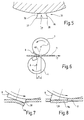
wird im Folgenden auf Figur 3 Bezug genommen. Die Bewegung
eines herausgegriffenen Punkts P0 der Walze 3 stellt
abgebildet auf eine sich mit dem Werkstück 4 bewegende
Fläche eine Zykloide dar. In Figur 3 wird dies für Punkte
P0, P1 des übertrieben dargestellten Stempels 8 veranschaulicht.If necessary, however, the
Der Stempel 8 weist eine radial nach außen weisende
Stirnfläche 27 auf, die von einer Schneidkante 28 begrenzt
wird. Die Schneidkante 28 tritt bei Drehung der
Walze 3 in Richtung des Pfeils 15 und bei Bewegung des
Werkstücks 4 in Richtung des Pfeils 18 zunächst mit ihrem
Punkt P0 mit dem Werkstück 11 in Berührung, der in Drehrichtung
15 vorn liegt. Der Punkt P0 liegt außerhalb eines
Wälzkreises 29, der durch das Verhältnis der Drehzahl der
Walze 3 zu der Bewegungsgeschwindigkeit des Werkstücks 11
festgelegt ist. Der Wälzkreis kann sowohl auf der Oberfläche
der Walze 3 als auch radial im Abstand zu dieser
festgelegt sein. Im vorliegenden Beispiel liegt er zwischen
der Stirnfläche 27 des Stempels 8 und der Mantelfläche
der Walze 3.The
Der Punkt P0 bewegt sich auf einer verlängerten
Zykloide, die, wenn die Drehzahl der Walze 3 und die
Vorschubgeschwindigkeit des Werkstücks 4 jeweils vollständig
konstant sind, eine typische Schleife aufweist.
Bei der vorliegenden Rotationsumformmaschine 1 wird
jedoch die Relativgeschwindigkeit zwischen dem Wälzkreis
29 und einer entsprechenden Linie des Werkstücks 4, auf
der der Wälzkreis abrollt, nicht konstant zu Null gemacht.
Dadurch kann die Fläche der von der Zykloide 31
eingeschlossenen Schleife, die der Punkt P0 durchläuft,
variiert und insbesondere vermindert werden. Die Relativgeschwindigkeit
zwischen dem Wälzkreis 29 und einer
Mittellinie 32 wird wenigstens im Bereich der Zykloidenschleife,
d.h. während des Eingriffs des Stempels 8 und
des Werkstücks 11 periodisch von Null verschieden gemacht,
so dass das Werkstück 11 in Bezug auf die Walze 3
beschleunigt oder verzögert wird. Im vorliegenden Beispiel
sind die Augenblicksgeschwindigkeiten des Werkstücks
11 und der Walze 3 so aufeinander abgestimmt, dass
der Punkt P0 eine zu einem Geradenstück entartete Zykloidenschleife
durchläuft. Dies kann erreicht werden, indem
der Punkt P0, der in Figur 3 durch die Koordinaten r0 und
f0 charakterisiert ist, auf einer Bahn geführt wird, die
den folgenden Bedingungen genügt:

Der Stempel 8 erfährt beim Eindringen in das Werkstück
11 und während er aus diesem wieder herausgeführt
wird eine Kippbewegung. Dabei ändert sich der Winkel
einer sich an die Schneidkante 28 anschliessenden Flanke
34 des Stempels zu dem Werkstück 11. Dies gilt sowohl für
eine schleifenförmige Bewegung der Schneidkante und des
Punkts P0, als auch bei einer deformierten Zykloidenbewegung,
bei der der Schleifenbereich zu einem Geradenstück
35 entartet oder verformt ist. Um zu vermeiden, dass die
Flanke 34 an entsprechenden Flächen des Werkstücks 4
drückt und somit einem erhöhten Verschleiß unterliegt,
ist es zweckmäßig, die Flanke 34, wie in Figur 5 dargestellt,
mit einer Ausnehmung 36 zu versehen, die die
Schneidkante 28 hintergreift. Die Ausnehmung 36 bildet
einen Freiraum oder Zwischenraum zu der von der Schneidkante
28 ausgeformten Fläche des Werkstücks 4. Innerhalb
des Freiraums ist eine Schwenkbewegung des Stempels 3
möglich. Im Anschluss an eine nacheilende Kante 37, d.h.
einen entsprechenden Bereich der Schneidkante 28, kann
ebenfalls eine Ausnehmung 38 vorgesehen sein, die trotz
der von diesem Schneidenpunkt durchgeführten Schleifenbewegung
einen übermäßigen Druck zwischen der Flanke des
Stempels 8 und dem Werkstück 4 zu vermeiden.The
Die Verformung der Zykloide 31 zu einer Kurve ohne
Schleife ermöglicht es, die Ausnehmung 36 relativ moderat
zu halten, was insbesondere eine gute Unterstützung der
Schneidkante 28 ermöglicht. Bei einer unveränderten
Zykloide mit Schleifenbewegung der Schneidkante 28 im
Punkt P0 oder lediglich geringer Verminderung der Fläche
der Schleife, wäre die Ausnehmung 36 entsprechend größer
auszuführen, wodurch die Schneidkante 28 empfindlicher
wird.The deformation of the
Die insoweit beschriebene Rotationsstanze 1 arbeitet
wie folgt:The
Während des Betriebs steuert eine Steuereinrichtung
die Antriebseinrichtung 16 und den Antrieb 20 so, dass
das Werkstück 11 in Bezug auf die Umfangsgeschwindigkeit
des Abrollkreises 29 zunächst etwas verlangsamt wird,
wenn die Schneidkante oder kurz bevor die Schneidkante 28
Berührung mit dem Werkstück 11 erhält. Zuvor war die
Relativgeschwindigkeit zwischen dem Abrollkreis 29 und
der Bezugslinie 32 Null. Nun ist sie etwas negativ. In
Annäherung an den unteren Umkehrpunkt der deformierten
Zykloide (P0) steigert sich die Relativgeschwindigkeit von
dem negativen Wert zunächst wieder auf Null und wird dann
positiv, während die Schneidkante 28 nach oben aus dem
Werkstück 11 herausgeführt wird. Ist die Schneidkante 28
außer Eingriff mit dem Werkstück, fällt die Relativgeschwindigkeit
zwischen dem Rollkreis 27 und der Bezugslinie
32 wieder auf Null ab, so dass der Rollkreis 29
praktisch schlupffrei auf der Bezugslinie 32 abrollt.During operation, a control device controls the drive device 16 and the
Zur Durchführung dieser Relativgeschwindigkeitsmodulation
zwischen den Stempeleingriffen sind die Walzen
3, 4 und die Vorschubeinrichtung 19 mit Positions- oder
Bewegungssensoren versehen, die es der Steuereinrichtung
gestatten, diese Geschwindigkeitsmodulation auf den
Eingriff der Stempel 8 mit dem Werkstück 11 zu synchronisieren.
Die Bewegungsvariation oder Modulation, d.h. die
temporäre Änderung der Drehzahl der Walze 3 kann gleichermaßen
für die Walze 4 durchgeführt werden. Alternativ
kann diese, wenn die Ausnehmungen 9 entsprechend groß
sind, auch mit konstanter Drehzahl laufen.To carry out this relative speed modulation
the rollers are between the stamping
Wie in Figur 6 dargestellt ist, müssen die Walzen 3,
4 der Rotationsstanzmaschine 1 nicht zwingend vertikal
übereinander angeordnet sein. Es ist auch möglich, die
Walzen 3, 4 in Transportrichtung T um einen Versatz S
gegeneinander versetzt so anzuordnen, dass eine gedachte
Verbindungslinie 40 zwischen den Drehachsen 7, 8 zu der
von dem Werkstück 11 definierten Ebene schräg geneigt
seht. Dies führt zu einer besseren Unterstützung des
Werkstücks 11 beim Aufsetzen des Stempels 8 auf das Werkstück
11, so dass dieses nicht verbogen wird.As shown in Figure 6, the
Wie in Figur 7 veranschaulicht, kann der Stempel 8
der Rotationsstanzmaschine 1 eine im Wesentlichen in
Umfangsrichtung angeordnete Stirnfläche aufweisen. Der
von dem Stempel 8 ausgeführte Schnitt ist dann ein ziehender
Schnitt. Das aus dem Werkstück 11 gestanzte Abfallstück
ha erhält bei dem Stanzvorgang eine gewisse
Krümmung. Während der ziehende Schnitt deutliche Vorteile
hinsichtlich der Gleichmäßigkeit der Belastung und des
Drehmomentbedarfs des Werkzeugs 2 hat, ist es jedoch auch
möglich, einen Schnitt herbeizuführen, bei dem die
Schneidkante 28 auf voller Länge, oder nahezu auf voller
Länge gleichzeitig mit dem Werkstück 11 in Eingriff
kommt. Dazu ist die von der Schneidkante 28 festgelegte
Fläche zu der Umfangsrichtung so geneigt, dass der Stempel
8 stirnseitig vollflächig auf dem Werkstück 11 aufsetzt.
Das ausgestanzte Teil 11a wird wenig oder nicht
deformiert und kann als Nutzteil dienen.As illustrated in FIG. 7, the
Bei einer Rotationsumformmaschine wird die Relativbewegung
zwischen einem Werkstück 11 und ein oder zwei
Walzen 3, 4 so beeinflusst, dass an den Walzen 3, 4
vorhandene Stempel 8 an ausgewählten Punkten eine Zykloidenbewegung
durchführen, bei der der Flächeninhalt vorhandener
Schleifen reduziert oder Schleifen ganz vermieden
werden. Dadurch kann der Flankenverschleiß der
Stempel vermindert werden. Darüberhinaus kann die Qualität
der erzeugten Werkstücke verbessert werden. Ergänzend
kann an der Flanke 34 des Stempels 8 eine Ausnehmung
angeordnet sein, die das Schwenken des Stempels bei
seiner Eintauchbewegung in das Werkstück 11 ohne erhöhten
Flankendruck gestattet.In a rotary forming machine, the relative movement
between a workpiece 11 and one or two
Claims (15)
dadurch gekennzeichnet,
characterized,
Applications Claiming Priority (2)
| Application Number | Priority Date | Filing Date | Title |
|---|---|---|---|
| DE1998132897 DE19832897B4 (en) | 1998-07-22 | 1998-07-22 | Rotationsumformmaschine |
| DE19832897 | 1998-07-22 |
Publications (2)
| Publication Number | Publication Date |
|---|---|
| EP0976471A2 true EP0976471A2 (en) | 2000-02-02 |
| EP0976471A3 EP0976471A3 (en) | 2003-04-16 |
Family
ID=7874876
Family Applications (1)
| Application Number | Title | Priority Date | Filing Date |
|---|---|---|---|
| EP99113299A Withdrawn EP0976471A3 (en) | 1998-07-22 | 1999-07-09 | Rotative forming machine |
Country Status (2)
| Country | Link |
|---|---|
| EP (1) | EP0976471A3 (en) |
| DE (1) | DE19832897B4 (en) |
Cited By (2)
| Publication number | Priority date | Publication date | Assignee | Title |
|---|---|---|---|---|
| WO2003035300A1 (en) * | 2001-10-25 | 2003-05-01 | Sundhagen, Lena | Method and tool for providing convexities |
| CN109043757A (en) * | 2018-06-08 | 2018-12-21 | 老凤祥东莞珠宝首饰有限公司 | Gold oil pressure reverse mould pendant circle hypervelocity marking molding machine |
Families Citing this family (4)
| Publication number | Priority date | Publication date | Assignee | Title |
|---|---|---|---|---|
| DE102012005005B4 (en) | 2012-03-13 | 2020-07-16 | Jürgen Hackert | Method and arrangement for the production of electrical sheets |
| GB2518596B (en) | 2013-08-28 | 2016-01-20 | Gkn Evo Edrive Systems Ltd | Variable pitch punch apparatus |
| DE102013018995B4 (en) | 2013-11-13 | 2015-06-18 | Jörg Franke | Plant for the rotary cutting of electrical sheets |
| DE102022121997A1 (en) | 2022-08-31 | 2024-02-29 | Fraunhofer-Gesellschaft zur Förderung der angewandten Forschung eingetragener Verein | Method and device for forming thin-walled sheet metal semi-finished products |
Citations (1)
| Publication number | Priority date | Publication date | Assignee | Title |
|---|---|---|---|---|
| US5040397A (en) | 1985-12-20 | 1991-08-20 | Bodnar Ernest R | Rotary apparatus and method |
Family Cites Families (5)
| Publication number | Priority date | Publication date | Assignee | Title |
|---|---|---|---|---|
| DE1962104A1 (en) * | 1969-12-11 | 1971-06-16 | Hubbuch Heinz Dipl Ing | Cutting tools in the form of rotating rolling tools |
| US5040379A (en) * | 1988-06-21 | 1991-08-20 | Daikin Industries, Ltd. | Temperature controller of liquid cooling system |
| NL9400739A (en) * | 1994-05-04 | 1995-12-01 | Geel Syst Bv | Method and device for making a building construction with a flat stiffened plate part. |
| US5887502A (en) * | 1995-09-26 | 1999-03-30 | Max Co., Ltd. | Rotary punching device |
| DE19815339A1 (en) * | 1998-04-06 | 1999-10-14 | Voith Sulzer Papiermasch Gmbh | Rolling machine and method for its operation |
-
1998
- 1998-07-22 DE DE1998132897 patent/DE19832897B4/en not_active Expired - Fee Related
-
1999
- 1999-07-09 EP EP99113299A patent/EP0976471A3/en not_active Withdrawn
Patent Citations (1)
| Publication number | Priority date | Publication date | Assignee | Title |
|---|---|---|---|---|
| US5040397A (en) | 1985-12-20 | 1991-08-20 | Bodnar Ernest R | Rotary apparatus and method |
Cited By (3)
| Publication number | Priority date | Publication date | Assignee | Title |
|---|---|---|---|---|
| WO2003035300A1 (en) * | 2001-10-25 | 2003-05-01 | Sundhagen, Lena | Method and tool for providing convexities |
| CN109043757A (en) * | 2018-06-08 | 2018-12-21 | 老凤祥东莞珠宝首饰有限公司 | Gold oil pressure reverse mould pendant circle hypervelocity marking molding machine |
| CN109043757B (en) * | 2018-06-08 | 2024-05-28 | 老凤祥东莞珠宝首饰有限公司 | Gold oil pressure reverse mould pendant ring overspeed mark shaping machine |
Also Published As
| Publication number | Publication date |
|---|---|
| EP0976471A3 (en) | 2003-04-16 |
| DE19832897B4 (en) | 2012-01-26 |
| DE19832897A1 (en) | 2000-01-27 |
Similar Documents
| Publication | Publication Date | Title |
|---|---|---|
| DE10141589B4 (en) | Method for operating a sheet-processing machine and machine for processing sheets | |
| DE112011105280B4 (en) | Polygon compensation coupling for chain and gear driven systems | |
| EP1711288B1 (en) | Joining apparatus | |
| DE9418810U1 (en) | Workpiece forming tool and lower punch for punching machine | |
| DE2638693A1 (en) | ROTATING PRINTING DEVICE | |
| EP2487014A1 (en) | Method and device for punching or perforating moving sheets of material | |
| EP1554109A2 (en) | Device for punching, stamping and/or shaping flat elements | |
| CH657292A5 (en) | DEVICE FOR GAUGING SHEET. | |
| WO1987002911A1 (en) | Comminution device | |
| DE69623409T2 (en) | Cutting device for cutting endless material webs | |
| DE19832897B4 (en) | Rotationsumformmaschine | |
| DE3856093T2 (en) | Die carrier arrangement in a shaping device with rotating rollers | |
| DE4431849A1 (en) | Push=through fastening process for metal sheets | |
| DE2804642A1 (en) | CONTAINER BOTTOM CUTTER DEVICE AND PROCEDURE | |
| DE60021885T2 (en) | POWER ADJUSTABLE ROTATING APPARATUS FOR WORKING TRACKS | |
| DE68927764T2 (en) | Machine for braking a series of sheet metal sheets moving closely in succession along a production line | |
| DE102022207528A1 (en) | Counter cylinder arrangement | |
| EP1840058B1 (en) | Device for decelerating and/or accelerating printed sheets or exemplars separated from a sheet like print substrate | |
| EP3967485A2 (en) | Folding box gluing machine with embossing device | |
| DE1602511A1 (en) | Device for feeding bandfoermigem material in punching machines and the like. | |
| DE3730132C2 (en) | ||
| EP2165783B1 (en) | Tool for a punch press for altering the tension state of a piece of sheet metal | |
| WO2015070834A1 (en) | System for rotation cutting | |
| DE3855312T2 (en) | Rotational molding process | |
| EP2719508A1 (en) | Drive device and punching machine with such a drive device |
Legal Events
| Date | Code | Title | Description |
|---|---|---|---|
| PUAI | Public reference made under article 153(3) epc to a published international application that has entered the european phase |
Free format text: ORIGINAL CODE: 0009012 |
|
| AK | Designated contracting states |
Kind code of ref document: A2 Designated state(s): AT BE CH CY DE DK ES FI FR GB GR IE IT LI LU MC NL PT SE |
|
| AX | Request for extension of the european patent |
Free format text: AL;LT;LV;MK;RO;SI |
|
| PUAL | Search report despatched |
Free format text: ORIGINAL CODE: 0009013 |
|
| AK | Designated contracting states |
Designated state(s): AT BE CH CY DE DK ES FI FR GB GR IE IT LI LU MC NL PT SE |
|
| AX | Request for extension of the european patent |
Extension state: AL LT LV MK RO SI |
|
| RIC1 | Information provided on ipc code assigned before grant |
Ipc: 7B 21D 22/08 B Ipc: 7B 26F 1/10 B Ipc: 7B 21D 28/36 A |
|
| AKX | Designation fees paid |
Designated state(s): AT BE CH CY DE DK ES FI FR GB GR IE IT LI LU MC NL PT SE |
|
| STAA | Information on the status of an ep patent application or granted ep patent |
Free format text: STATUS: THE APPLICATION IS DEEMED TO BE WITHDRAWN |
|
| 18D | Application deemed to be withdrawn |
Effective date: 20031017 |