EP0973048B1 - Methods and apparatus for reducing spectral artifacts in a computed tomograph system - Google Patents
Methods and apparatus for reducing spectral artifacts in a computed tomograph system Download PDFInfo
- Publication number
- EP0973048B1 EP0973048B1 EP99305495A EP99305495A EP0973048B1 EP 0973048 B1 EP0973048 B1 EP 0973048B1 EP 99305495 A EP99305495 A EP 99305495A EP 99305495 A EP99305495 A EP 99305495A EP 0973048 B1 EP0973048 B1 EP 0973048B1
- Authority
- EP
- European Patent Office
- Prior art keywords
- scintillator
- collimator
- gap
- detector
- array
- Prior art date
- Legal status (The legal status is an assumption and is not a legal conclusion. Google has not performed a legal analysis and makes no representation as to the accuracy of the status listed.)
- Expired - Lifetime
Links
Images

Classifications
-
- A—HUMAN NECESSITIES
- A61—MEDICAL OR VETERINARY SCIENCE; HYGIENE
- A61B—DIAGNOSIS; SURGERY; IDENTIFICATION
- A61B6/00—Apparatus for radiation diagnosis, e.g. combined with radiation therapy equipment
- A61B6/02—Devices for diagnosis sequentially in different planes; Stereoscopic radiation diagnosis
- A61B6/03—Computerised tomographs
- A61B6/032—Transmission computed tomography [CT]
-
- A—HUMAN NECESSITIES
- A61—MEDICAL OR VETERINARY SCIENCE; HYGIENE
- A61B—DIAGNOSIS; SURGERY; IDENTIFICATION
- A61B6/00—Apparatus for radiation diagnosis, e.g. combined with radiation therapy equipment
- A61B6/06—Diaphragms
-
- A—HUMAN NECESSITIES
- A61—MEDICAL OR VETERINARY SCIENCE; HYGIENE
- A61B—DIAGNOSIS; SURGERY; IDENTIFICATION
- A61B6/00—Apparatus for radiation diagnosis, e.g. combined with radiation therapy equipment
- A61B6/40—Apparatus for radiation diagnosis, e.g. combined with radiation therapy equipment with arrangements for generating radiation specially adapted for radiation diagnosis
- A61B6/4064—Apparatus for radiation diagnosis, e.g. combined with radiation therapy equipment with arrangements for generating radiation specially adapted for radiation diagnosis specially adapted for producing a particular type of beam
- A61B6/4085—Cone-beams
-
- A—HUMAN NECESSITIES
- A61—MEDICAL OR VETERINARY SCIENCE; HYGIENE
- A61B—DIAGNOSIS; SURGERY; IDENTIFICATION
- A61B6/00—Apparatus for radiation diagnosis, e.g. combined with radiation therapy equipment
- A61B6/44—Constructional features of apparatus for radiation diagnosis
- A61B6/4411—Constructional features of apparatus for radiation diagnosis the apparatus being modular
-
- G—PHYSICS
- G01—MEASURING; TESTING
- G01T—MEASUREMENT OF NUCLEAR OR X-RADIATION
- G01T1/00—Measuring X-radiation, gamma radiation, corpuscular radiation, or cosmic radiation
- G01T1/29—Measurement performed on radiation beams, e.g. position or section of the beam; Measurement of spatial distribution of radiation
- G01T1/2914—Measurement of spatial distribution of radiation
- G01T1/2985—In depth localisation, e.g. using positron emitters; Tomographic imaging (longitudinal and transverse section imaging; apparatus for radiation diagnosis sequentially in different planes, steroscopic radiation diagnosis)
-
- A—HUMAN NECESSITIES
- A61—MEDICAL OR VETERINARY SCIENCE; HYGIENE
- A61B—DIAGNOSIS; SURGERY; IDENTIFICATION
- A61B6/00—Apparatus for radiation diagnosis, e.g. combined with radiation therapy equipment
- A61B6/40—Apparatus for radiation diagnosis, e.g. combined with radiation therapy equipment with arrangements for generating radiation specially adapted for radiation diagnosis
- A61B6/4021—Apparatus for radiation diagnosis, e.g. combined with radiation therapy equipment with arrangements for generating radiation specially adapted for radiation diagnosis involving movement of the focal spot
Definitions
- This invention relates generally to computed tomograph (CT) imaging and, more particularly, to reducing spectral artifacts in a multislice CT system.
- CT computed tomograph
- an x-ray source projects a fan-shaped beam which is collimated to lie within an X-Y plane of a Cartesian coordinate system and generally referred to as the "imaging plane".
- the x-ray beam passes through the object being imaged, such as a patient.
- the beam after being attenuated by the object, impinges upon an array of radiation detectors.
- the intensity of the attenuated beam radiation received at the detector array is dependent upon the attenuation of the x-ray beam by the object.
- Each detector element of the array produces a separate electrical signal that is a measurement of the beam attenuation at the detector location.
- the attenuation measurements from all the detectors are acquired separately to produce a transmission profile.
- X-ray sources typically include x-ray tubes, which emit the x-ray beam at a focal spot.
- X-ray detectors typically include a collimator for collimating x-ray beams received at the detector. A scintillator is located adjacent the collimator, and photodiodes are positioned adjacent the scintillator.
- Multislice CT systems are used to obtain data for an increased number of slices during a scan.
- Known multislice systems typically include detectors generally known as 2-D detectors. With such 2-D detectors, a plurality of detector elements form separate channels arranged in columns and rows. Each row of detectors forms a separate slice. For example, a two-slice detector has two rows of detector elements, and a four-slice detector has four rows of detector elements.
- multiple rows of detector cells are simultaneously impinged by the x-ray beam, and therefore data for several slices is obtained.
- Multislice detectors are typically segmented into a series of individual scintillator cells in the X and Z axes. These scintillator cells can be separated by narrow gaps of only a few micrometers between adjacent cells. The gaps are filled with a light reflecting material.
- the detector elements could accept off-axis, or scattered, x-ray beams which decrease contrast resolution and increase image artifacts.
- US-A-5 373 162 discloses a radiation detector comprising an array of detector elements.
- a collimator is provided such that each of the collimator plates is placed over the space between adjacent detector elements.
- a reflector is provided between adjacent detector elements. The thickness of the reflector is selected to be sufficiently greater than that of the thickness of the collimator plate to accommodate a critical quantity of heat stored in an anode.
- US-A-4 180 737 discloses a solid state x-ray detector. Collimating members are provided between adjacent scintillator elements. A collimating members provided between adjacent scintillator elements are thinner than the gaps between adjacent scintillator elements.
- US-A-4 731 534 discloses an x-ray detector system with collimator plates provided over the interface between adjacent scintillator crystals.
- a detector array that collimates and separates the x-ray beams toward individual detector elements to reduce scatter and spectral artifacts.
- a detector array collimator that protects the gaps between the elements from x-ray beams so that radiation damage, beam hardening, punch through noise and spectral effects of the light reflecting material is minimized.
- a detector for a multislice computed tomography system comprising: a scintillator array having at least first and second cells with a gap therebetween., and a collimator having at least one collimator plate, the centerline of said collimator plate displaced from the centerline of said scintillator array gap.
- the array may comprises at least one X-axis scintillator gap and at least one Z-axis scintillator gap.
- the collimator plate centerline is displaced from the centerline of said X-axis scintillator gap.
- the width of said collimator plate is greater than the width of said X-axis scintillator gap.
- the scintillator gap may comprise a 100 micrometer gap and the collimator plate may be 200 micrometers wide.
- the scintillator array may comprise a plurality of cells and the collimator may comprise a plurality of collimator plates.
- a multislice computed tomography system for generating images of an object, said system comprising an x-ray source for emitting x-ray beams, said beams emitted from a source focus; a multislice detector comprising a scintillator array having at least first and second cells with a gap therebetween., and a collimator having at least one collimator plate for generating an x-ray shadow, said collimator positioned over said detector gap so that said shadow is centered over said detector gap.
- the centerline of said collimator plate is not collinear with centerline of said scintillator gap.
- the array may comprises at least one X-axis scintillator gap and at least one Z-axis scintillator gap.
- the centerline of said collimator plate is displaced from the centerline of said X-axis scintillator gap.
- the width of said collimator plate may be greater than the width of said X-axis scintillator gap and the scintillator gap may comprise a 100 micrometer gap.
- the collimator plate may be 200 micrometers wide.
- the scintillator array may comprise a plurality of cells and the collimator may comprise a plurality of collimator plates.
- a method of reducing spectral artifacts in a multislice computed tomography system including a x-ray source for emitting x-ray beams, at least one multislice detector comprising a scintillator array having at least first and second cells with a gap therebetween, and a collimator having at least one collimator plate, said method comprising the step of positioning the collimator plate over the detector gap so that a shadow is centered over the detector gap.
- Positioning of the collimator plate over the detector gap comprises the step of positioning the collimator plate so that the collimator plate centerline is not collinear with the scintillator gap centerline.
- the scintillator array may comprise at least one X axis scintillator gap and at least one Z axis scintillator gap and wherein positioning the collimator plate over the detector gap comprises the step of positioning the collimator plate over the X axis scintillator gap.
- the collimator plate may comprise a centerline and positioning the collimator plate over the X axis scintillator gap may comprises the step of positioning the collimator plate so that the collimator plate centerline is displaced from the X axis scintillator gap centerline.
- the width of the collimator plate may be greater than the width of the X axis scintillator gap.
- the scintillator gap may comprise a 100 micrometer gap and the collimator plate may be 200 micrometers wide.
- the scintillator array may includes a plurality of cells and a plurality of collimator plates, and positioning of the collimator plate over the X axis scintillator gap may comprise the step of positioning the collimator plates over the X axis scintillator gaps.
- a collimator is included for reducing scatter, spectral artifacts and x-ray damage.
- the detector array includes a detector housing, a plurality of detector modules and a collimator having a plurality of collimator plates.
- Each detector module is mounted to the detector housing and includes a photodiode array optically coupled to a scintillator array.
- the collimator plates are configured so that x-ray beam signals directed at the scintillator array are allowed to pass and those signals directed toward the gaps in the scintillator array are blocked.
- the detector array is fabricated by spacing and securing each collimator plate to the detector housing so that a x-ray beam shadow is centered over the scintillator gap. More specifically, each collimator plate is positioned so that the centerline of the collimator plate is displaced from, or not collinear with, the centerline of the scintillator array gap. In one embodiment, one wire is then extended the length of the collimator perpendicular to the longitudinal axis of the plates forming a plurality of sections. The number of sections corresponds to the size of the photodiode array so that the X-ray beams are separated to correspond to the number of detector elements.
- the above described detector array enables X-ray beams to be separated so that the X-ray beams impinge only on the scintillator array resulting in reduced scatter and spectral artifacts. Additionally, the collimator prevents the x-ray beams from impinging upon the scintillator array gaps. As a result, radiation damage to the scintillator gaps is reduced.
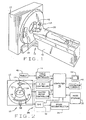
- a computed tomography (CT) imaging system 10 is shown as including a gantry 12 representative of a "third generation" CT scanner.
- Gantry 12 has an x-ray source 14 that projects a beam of x-rays 16 toward a detector array 18 on the opposite side of gantry 12.
- Detector array 18 is formed by detector modules 20 which together sense the projected x-rays that pass through a medical patient 22.
- Each detector module 20 produces electrical signals that represent the intensity of impinging x-ray beams and hence the attenuation of the beams as they pass through patient 22.
- gantry 12 and the components mounted thereon rotate about a center of rotation 24.
- Control mechanism 26 includes an x-ray controller 28 that provides power and timing signals to x-ray source 14 and a gantry motor controller 30 that controls the rotational speed and position of gantry 12.
- a data acquisition system (DAS) 32 in control mechanism 26 samples analog data from detector modules 20 and converts the data to digital signals for subsequent processing.
- An image reconstructor 34 receives sampled and digitized x-ray data from DAS 32 and performs high speed image reconstruction. The reconstructed image is applied as an input to a computer 36 which stores the image in a mass storage device 38.
- DAS data acquisition system
- Computer 36 also receives commands and scanning parameters from an operator via console 40 that has a keyboard.
- An associated cathode ray tube display 42 allows the operator to observe the reconstructed image and other data from computer 36.
- the operator supplied commands and parameters are used by computer 36 to provide control signals and information to DAS 32, x-ray controller 28 and gantry motor controller 30.
- computer 36 operates a table motor controller 44 which controls a motorized table 46 to position patient 22 in gantry 12. Particularly, table 46 moves portions of patient 22 through a gantry opening 48.
- detector array 18 includes a plurality of detector modules 20 secured to an arc shaped detector housing 50.
- Each detector module 20 includes a multidimensional photodiode array 52 and a multidimensional scintillator array 56 positioned in front of and adjacent to photodiode array 52.
- One photodiode array that may be used is described in copending U.S. Patent Application Serial No. 08/978,805 , entitled, Photodiode Array For A Scalable Multislice Scanning Computed Tomography System, which is assigned to the present assignee.
- One scintillator array that may be used is described in copending U.S. Patent Application Serial No. 08/977,439 , entitled, Scintillator For A Multislice Computed Tomograph System, which is assigned to the present assignee.
- Scintillator array 56 includes a plurality of elements, or cells (not shown) separated by narrow gaps (not shown) between adjacent cells. Scintillator array 56 includes X-axis and Z-axis gaps. The gaps are filled with a light reflective material. Photodiode array 52 includes a plurality of photodiodes 58 which are optically coupled to scintillator array 56. Photodiodes 58 generate electrical output signals 60 representative of the light output by each scintillator of scintillator array 56.
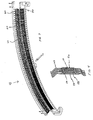
- Detector array 18 also includes a collimator 62 positioned in front of an adjacent scintillator array 56 to collimate x-ray beams 16 before such beams impinge upon scintillator array 56.
- collimator 62 includes a plurality of plates 64 and at least one wire 66. Plates 64 are spaced and secured together so that the longitudinal axis of each plate 64 extends substantially parallel to the longitudinal axis of each adjacent plate 64. Plates 64 are inserted in slots (not shown) located in housing 50 and bonded at the top and bottom of plates 64. Plates 64 and wire 66 are made, in one embodiment, of tungsten. Wire 66 extends the length of collimator 62 substantially perpendicular to the longitudinal axis of plates 64 and is inserted in horizontal slots (not shown) in plates 64 and bonded.
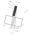
- detector array 18 is fabricated by positioning plates 64 over scintillator array X-axis gaps 70 so that the centerline of each collimator plate 64 is displaced from, or not collinear with, the centerline of each scintillator array X-axis gap 70. More specifically and as a result of scintillator array 56 being flat and the radial emission of x-ray beams 16, collimator plates 64 are positioned so that a x-ray shadow is centered over each X-axis scintillator gap 70. In one embodiment, collimator plates 64 are wider than scintillator X-axis gaps 70. For example, X-axis scintillator gaps 70 may be 100 micrometers wide and each collimator plate 64 may be 200 micrometers wide.
- detector modules 20 are secured to detector housing 50 and are skewed, or rotated, along an arc of about ten minutes.
- Positioning of collimator plates 64 causes the effective collimation aperture for all detector cells (not shown) to increase or decrease signal level similarly as a result of x-axis focal spot motion.
- the signal level of adjacent detector module cells change in a similar direction as a result of x-axis focal spot motion.
- differential error caused by x-axis focal spot motion is reduced.
- Plates 64 and wire 66 create a plurality of sections (not shown) with each section having an active area and an inactive area (not shown).
- the active areas separate the X-rays so that x-ray beams 16 are allowed to pass through collimator 62 to scintillator array 56.
- X-ray beams 16 are prevented from impinging upon scintillator array gaps 70 and from projecting through the edges of scintillator elements by inactive areas created by shadow of collimator 62. More specifically, x-ray beams 16 are prevented from projecting through a shortened path length of scintillator array 52, thereby reducing spectral errors.
- the centerline of collimator plates 64 may be displaced distance D from the centerline of the gaps 70 so that x-ray beams are prevented from projecting through a portion of scintillator array 56 and so that x-ray beams 16 do not impinge upon the light reflecting material.
- the number of sections is dependent on the size of scintillator array 56 and photodiode array 52.
- the area of scintillator array 56 directly below wire 66 is protected from impinging x-ray beams 16.
- wire 66 may be positioned above each scintillator array Z-axis gap (not shown) to protect reflective material from radiation damage and reduce penetration of x-ray beams 16 toward photodiode array 52.
- the number of collimator wires 66 is one greater than the number of rows in scintillator array 56 so that each gap is protected.
- detector array 18 includes fifty-seven detector modules 20.
- Each detector module 20 includes a photodiode array 52 and scintillator array 56, each having an array size of 16 x 16 so that array 18 has 16 rows and 912 columns (16 x 57 modules).
- collimator 62 includes seventeen wires 66 and 913 plates 64 allowing sixteen simultaneous slices of data to be collected with each rotation of gantry 12. Additional examples include, a two-slice mode of operation including three wires 66; and a four slice mode of operation including five wires 66. Additional modes beyond those described are possible.
- collimator 62 allows a portion of x-ray beams 16 to impinge upon detector modules 20. Specifically, as x-ray beams 16 are radially emitted from the focal spot of tube 14, a portion of the x-rays impinge scintillator array 56. Those x-ray beams directed to the scintillator gaps are blocked by collimator plates 64 and wires 66. As a result, radiation damage and artifacts are reduced. In addition, centering of the collimator shadow over the scintillator gaps reduces spectral errors caused by movement of the x-ray tube focal spot.
- the above described detector array reduces image artifacts by collimating the x-ray beams toward individual detector elements.
- the above described detector collimator reduces spectral artifacts by preventing X-ray beams from projecting through the scintillator array elements along a shortened path length. Additionally, the above described detector collimator protects the gaps between the scintillator array elements from x-ray beams so that radiation damage to the light reflecting material is minimized.
Description
- This invention relates generally to computed tomograph (CT) imaging and, more particularly, to reducing spectral artifacts in a multislice CT system.
- In at least some computed tomograph (CT) imaging system configurations, an x-ray source projects a fan-shaped beam which is collimated to lie within an X-Y plane of a Cartesian coordinate system and generally referred to as the "imaging plane". The x-ray beam passes through the object being imaged, such as a patient. The beam, after being attenuated by the object, impinges upon an array of radiation detectors. The intensity of the attenuated beam radiation received at the detector array is dependent upon the attenuation of the x-ray beam by the object. Each detector element of the array produces a separate electrical signal that is a measurement of the beam attenuation at the detector location. The attenuation measurements from all the detectors are acquired separately to produce a transmission profile.
- In known third generation CT systems, the x-ray source and the detector array are rotated with a gantry within the imaging plane and around the object to be imaged so that the angle at which the x-ray beam intersects the object constantly changes. X-ray sources typically include x-ray tubes, which emit the x-ray beam at a focal spot. X-ray detectors typically include a collimator for collimating x-ray beams received at the detector. A scintillator is located adjacent the collimator, and photodiodes are positioned adjacent the scintillator.
- Multislice CT systems are used to obtain data for an increased number of slices during a scan. Known multislice systems typically include detectors generally known as 2-D detectors. With such 2-D detectors, a plurality of detector elements form separate channels arranged in columns and rows. Each row of detectors forms a separate slice. For example, a two-slice detector has two rows of detector elements, and a four-slice detector has four rows of detector elements. During a multislice scan, multiple rows of detector cells are simultaneously impinged by the x-ray beam, and therefore data for several slices is obtained.
- Multislice detectors are typically segmented into a series of individual scintillator cells in the X and Z axes. These scintillator cells can be separated by narrow gaps of only a few micrometers between adjacent cells. The gaps are filled with a light reflecting material. The detector elements could accept off-axis, or scattered, x-ray beams which decrease contrast resolution and increase image artifacts.
-
US-A-5 373 162 discloses a radiation detector comprising an array of detector elements. A collimator is provided such that each of the collimator plates is placed over the space between adjacent detector elements. A reflector is provided between adjacent detector elements. The thickness of the reflector is selected to be sufficiently greater than that of the thickness of the collimator plate to accommodate a critical quantity of heat stored in an anode. -
US-A-4 180 737 discloses a solid state x-ray detector. Collimating members are provided between adjacent scintillator elements. A collimating members provided between adjacent scintillator elements are thinner than the gaps between adjacent scintillator elements. -
US-A-4 731 534 discloses an x-ray detector system with collimator plates provided over the interface between adjacent scintillator crystals. - Accordingly, it would be desirable to provide a detector array that collimates and separates the x-ray beams toward individual detector elements to reduce scatter and spectral artifacts. In addition, it is desirable to provide a detector array collimator that protects the gaps between the elements from x-ray beams so that radiation damage, beam hardening, punch through noise and spectral effects of the light reflecting material is minimized.
- Aspects of the present invention are defined in the accompanying claims.
- In an embodiment of the invention, there is provided a detector for a multislice computed tomography system, said detector comprising: a scintillator array having at least first and second cells with a gap therebetween., and a collimator having at least one collimator plate, the centerline of said collimator plate displaced from the centerline of said scintillator array gap.
- The array may comprises at least one X-axis scintillator gap and at least one Z-axis scintillator gap.
- The collimator plate centerline is displaced from the centerline of said X-axis scintillator gap. The width of said collimator plate is greater than the width of said X-axis scintillator gap. The scintillator gap may comprise a 100 micrometer gap and the collimator plate may be 200 micrometers wide.
- The scintillator array may comprise a plurality of cells and the collimator may comprise a plurality of collimator plates.
- In an embodiment of the invention, there is provided a multislice computed tomography system for generating images of an object, said system comprising an x-ray source for emitting x-ray beams, said beams emitted from a source focus; a multislice detector comprising a scintillator array having at least first and second cells with a gap therebetween., and a collimator having at least one collimator plate for generating an x-ray shadow, said collimator positioned over said detector gap so that said shadow is centered over said detector gap.
- The centerline of said collimator plate is not collinear with centerline of said scintillator gap.
- The array may comprises at least one X-axis scintillator gap and at least one Z-axis scintillator gap. The centerline of said collimator plate is displaced from the centerline of said X-axis scintillator gap.
- The width of said collimator plate may be greater than the width of said X-axis scintillator gap and the scintillator gap may comprise a 100 micrometer gap. The collimator plate may be 200 micrometers wide.
- The scintillator array may comprise a plurality of cells and the collimator may comprise a plurality of collimator plates.
- According to a third aspect of the invention, there is provided a method of reducing spectral artifacts in a multislice computed tomography system, the system including a x-ray source for emitting x-ray beams, at least one multislice detector comprising a scintillator array having at least first and second cells with a gap therebetween, and a collimator having at least one collimator plate, said method comprising the step of positioning the collimator plate over the detector gap so that a shadow is centered over the detector gap.
- Positioning of the collimator plate over the detector gap comprises the step of positioning the collimator plate so that the collimator plate centerline is not collinear with the scintillator gap centerline.
- The scintillator array may comprise at least one X axis scintillator gap and at least one Z axis scintillator gap and wherein positioning the collimator plate over the detector gap comprises the step of positioning the collimator plate over the X axis scintillator gap.
- The collimator plate may comprise a centerline and positioning the collimator plate over the X axis scintillator gap may comprises the step of positioning the collimator plate so that the collimator plate centerline is displaced from the X axis scintillator gap centerline.
- The width of the collimator plate may be greater than the width of the X axis scintillator gap. The scintillator gap may comprise a 100 micrometer gap and the collimator plate may be 200 micrometers wide.
- The scintillator array may includes a plurality of cells and a plurality of collimator plates, and positioning of the collimator plate over the X axis scintillator gap may comprise the step of positioning the collimator plates over the X axis scintillator gaps.
- In one embodiment, a collimator is included for reducing scatter, spectral artifacts and x-ray damage. The detector array includes a detector housing, a plurality of detector modules and a collimator having a plurality of collimator plates. Each detector module is mounted to the detector housing and includes a photodiode array optically coupled to a scintillator array. The collimator plates are configured so that x-ray beam signals directed at the scintillator array are allowed to pass and those signals directed toward the gaps in the scintillator array are blocked.
- In one embodiment, the detector array is fabricated by spacing and securing each collimator plate to the detector housing so that a x-ray beam shadow is centered over the scintillator gap. More specifically, each collimator plate is positioned so that the centerline of the collimator plate is displaced from, or not collinear with, the centerline of the scintillator array gap. In one embodiment, one wire is then extended the length of the collimator perpendicular to the longitudinal axis of the plates forming a plurality of sections. The number of sections corresponds to the size of the photodiode array so that the X-ray beams are separated to correspond to the number of detector elements.
- The above described detector array enables X-ray beams to be separated so that the X-ray beams impinge only on the scintillator array resulting in reduced scatter and spectral artifacts. Additionally, the collimator prevents the x-ray beams from impinging upon the scintillator array gaps. As a result, radiation damage to the scintillator gaps is reduced.
- The invention will now be described in greater detail, by way of example, with reference to the drawings, in which:-
- Figure 1 is a pictorial view of a CT imaging system.
- Figure 2 is a block schematic diagram of the system illustrated in Figure 1.
- Figure 3 is a perspective view of a CT system detector array in accordance with the present invention.
- Figure 4 is a perspective view of a detector module shown in Figure 3.
- Figure 5 is a perspective view of a collimator in accordance with the present invention.
- Figure 6 is a side view of a portion of a detector module shown in Figure 4.
- Referring to Figures 1 and 2, a computed tomography (CT)
imaging system 10 is shown as including agantry 12 representative of a "third generation" CT scanner.Gantry 12 has anx-ray source 14 that projects a beam ofx-rays 16 toward adetector array 18 on the opposite side ofgantry 12.Detector array 18 is formed bydetector modules 20 which together sense the projected x-rays that pass through amedical patient 22. Eachdetector module 20 produces electrical signals that represent the intensity of impinging x-ray beams and hence the attenuation of the beams as they pass throughpatient 22. During a scan to acquire x-ray projection data,gantry 12 and the components mounted thereon rotate about a center ofrotation 24. - Rotation of
gantry 12 and the operation ofx-ray source 14 are governed by acontrol mechanism 26 ofCT system 10.Control mechanism 26 includes anx-ray controller 28 that provides power and timing signals to x-raysource 14 and agantry motor controller 30 that controls the rotational speed and position ofgantry 12. A data acquisition system (DAS) 32 incontrol mechanism 26 samples analog data fromdetector modules 20 and converts the data to digital signals for subsequent processing. Animage reconstructor 34 receives sampled and digitized x-ray data fromDAS 32 and performs high speed image reconstruction. The reconstructed image is applied as an input to acomputer 36 which stores the image in amass storage device 38. -
Computer 36 also receives commands and scanning parameters from an operator viaconsole 40 that has a keyboard. An associated cathoderay tube display 42 allows the operator to observe the reconstructed image and other data fromcomputer 36. The operator supplied commands and parameters are used bycomputer 36 to provide control signals and information toDAS 32,x-ray controller 28 andgantry motor controller 30. In addition,computer 36 operates atable motor controller 44 which controls a motorized table 46 to positionpatient 22 ingantry 12. Particularly, table 46 moves portions ofpatient 22 through agantry opening 48. - As shown in Figures 3 and 4,
detector array 18 includes a plurality ofdetector modules 20 secured to an arc shapeddetector housing 50. Eachdetector module 20 includes a multidimensional photodiode array 52 and amultidimensional scintillator array 56 positioned in front of and adjacent to photodiode array 52. One photodiode array that may be used is described in copendingU.S. Patent Application Serial No. 08/978,805 , entitled, Photodiode Array For A Scalable Multislice Scanning Computed Tomography System, which is assigned to the present assignee. One scintillator array that may be used is described in copendingU.S. Patent Application Serial No. 08/977,439 , entitled, Scintillator For A Multislice Computed Tomograph System, which is assigned to the present assignee. -
Scintillator array 56 includes a plurality of elements, or cells (not shown) separated by narrow gaps (not shown) between adjacent cells.Scintillator array 56 includes X-axis and Z-axis gaps. The gaps are filled with a light reflective material. Photodiode array 52 includes a plurality ofphotodiodes 58 which are optically coupled toscintillator array 56.Photodiodes 58 generate electrical output signals 60 representative of the light output by each scintillator ofscintillator array 56. -
Detector array 18 also includes acollimator 62 positioned in front of anadjacent scintillator array 56 to collimate x-ray beams 16 before such beams impinge uponscintillator array 56. Referring to Figure 5,collimator 62 includes a plurality ofplates 64 and at least one wire 66.Plates 64 are spaced and secured together so that the longitudinal axis of eachplate 64 extends substantially parallel to the longitudinal axis of eachadjacent plate 64.Plates 64 are inserted in slots (not shown) located inhousing 50 and bonded at the top and bottom ofplates 64.Plates 64 and wire 66 are made, in one embodiment, of tungsten. Wire 66 extends the length ofcollimator 62 substantially perpendicular to the longitudinal axis ofplates 64 and is inserted in horizontal slots (not shown) inplates 64 and bonded. - Referring to Figure 6,
detector array 18 is fabricated by positioningplates 64 over scintillator array X-axis gaps 70 so that the centerline of eachcollimator plate 64 is displaced from, or not collinear with, the centerline of each scintillator array X-axis gap 70. More specifically and as a result ofscintillator array 56 being flat and the radial emission of x-ray beams 16,collimator plates 64 are positioned so that a x-ray shadow is centered over each X-axis scintillator gap 70. In one embodiment,collimator plates 64 are wider than scintillator X-axis gaps 70. For example, X-axis scintillator gaps 70 may be 100 micrometers wide and eachcollimator plate 64 may be 200 micrometers wide. - In one embodiment,
detector modules 20 are secured todetector housing 50 and are skewed, or rotated, along an arc of about ten minutes. Positioning ofcollimator plates 64 causes the effective collimation aperture for all detector cells (not shown) to increase or decrease signal level similarly as a result of x-axis focal spot motion. Specifically, the signal level of adjacent detector module cells change in a similar direction as a result of x-axis focal spot motion. As a result, differential error caused by x-axis focal spot motion is reduced. -
Plates 64 and wire 66 create a plurality of sections (not shown) with each section having an active area and an inactive area (not shown). The active areas separate the X-rays so that x-ray beams 16 are allowed to pass throughcollimator 62 toscintillator array 56. X-ray beams 16 are prevented from impinging upon scintillator array gaps 70 and from projecting through the edges of scintillator elements by inactive areas created by shadow ofcollimator 62. More specifically, x-ray beams 16 are prevented from projecting through a shortened path length of scintillator array 52, thereby reducing spectral errors. For example, the centerline ofcollimator plates 64 may be displaced distance D from the centerline of the gaps 70 so that x-ray beams are prevented from projecting through a portion ofscintillator array 56 and so that x-ray beams 16 do not impinge upon the light reflecting material. - The number of sections is dependent on the size of
scintillator array 56 and photodiode array 52. The area ofscintillator array 56 directly below wire 66 is protected from impinging x-ray beams 16. For example, wire 66 may be positioned above each scintillator array Z-axis gap (not shown) to protect reflective material from radiation damage and reduce penetration of x-ray beams 16 toward photodiode array 52. In one embodiment, the number of collimator wires 66 is one greater than the number of rows inscintillator array 56 so that each gap is protected. - For example, in a sixteen-slice mode of operation,
detector array 18 includes fifty-sevendetector modules 20. Eachdetector module 20 includes a photodiode array 52 andscintillator array 56, each having an array size of 16 x 16 so thatarray 18 has 16 rows and 912 columns (16 x 57 modules). As a result,collimator 62 includes seventeen wires 66 and 913plates 64 allowing sixteen simultaneous slices of data to be collected with each rotation ofgantry 12. Additional examples include, a two-slice mode of operation including three wires 66; and a four slice mode of operation including five wires 66. Additional modes beyond those described are possible. - In operation, as x-ray beams 16 are projected toward
detector array 18,collimator 62 allows a portion of x-ray beams 16 to impinge upondetector modules 20. Specifically, as x-ray beams 16 are radially emitted from the focal spot oftube 14, a portion of the x-rays impingescintillator array 56. Those x-ray beams directed to the scintillator gaps are blocked bycollimator plates 64 and wires 66. As a result, radiation damage and artifacts are reduced. In addition, centering of the collimator shadow over the scintillator gaps reduces spectral errors caused by movement of the x-ray tube focal spot. - The above described detector array reduces image artifacts by collimating the x-ray beams toward individual detector elements. In addition, the above described detector collimator reduces spectral artifacts by preventing X-ray beams from projecting through the scintillator array elements along a shortened path length. Additionally, the above described detector collimator protects the gaps between the scintillator array elements from x-ray beams so that radiation damage to the light reflecting material is minimized.
- From the preceding description of various embodiments of the present invention, it is evident that the objects of the invention are attained. Although the invention has been described and illustrated in detail, it is to be clearly understood that the same is intended by way of illustration and example only and is not to be taken by way of limitation.
Claims (7)
- A detector (18) for a multislice computed tomography system (10) arranged to radially emit x-ray beams, said detector (18) comprising:a scintillator array (56) comprising at least first and second cells with a gap therebetween, the scintillator array (56) being flat;a post-patient collimator (62) positioned in front of the scintillator array (56), said post-patient collimator (62) comprising at least one collimator plate (64);characterized in that said post-patient collimator (62) is arranged to be positioned relative to the scintillator array (56) such that a centerline of said collimator plate (64) is displaced from a centerline of said scintillator array gap so that an x-ray shadow is centered over each scintillator array gap; and
the at least one collimator plate (64) being wider than the gap between said adjacent first and second cells of the scintillator array (56). - A detector (18) in accordance with Claim 1 wherein said array (56) comprises at least one X-axis scintillator gap (70) in a first direction and at least one Z-axis scintillator gap in a direction orthogonal to the first direction.
- A detector (18) in accordance with Claim 2 wherein said collimator plate centerline is displaced from the centerline of said scintillator gap (70) in a first X-axis direction.
- A detector (18) in accordance with Claim 3 wherein the width of said collimator plate (64) is greater than the width of said scintillator gap (70) in a first X-axis direction.
- A detector (18) in accordance with any preceding Claim wherein said collimator (62) comprises a plurality of collimator plates (64).
- A multislice computed tomography system (10) for generating images of an object, said system (10) comprising:a x-ray source (14) for emitting x-ray beams (16), said beams (16) emitted from a source focus; anda detector (18) according to any preceding claim.
- A method of reducing spectral artifacts in a multislice computed tomography system, the system including a x-ray source for radially emitting x-ray beams, at least one multislice detector comprising a flat scintillator array having at least first and second cells with a gap therebetween, and a post-patient collimator positioned in front of the scintillator array having at least one collimator plate, said method being characterised by the step of positioning the post patient collimator plate over the scintillator gap with a centreline of the collimator plate displaced from a centreline of the scintillator gap so that when x-ray beams are emitted from the x-ray source a shadow of the collimator plate is centred over each scintillator gap and by the at least one collimator plate being wider than the gap between adjacent first and second cells of the scintillator array.
Applications Claiming Priority (2)
| Application Number | Priority Date | Filing Date | Title |
|---|---|---|---|
| US118397 | 1998-07-17 | ||
| US09/118,397 US6266434B1 (en) | 1998-07-17 | 1998-07-17 | Methods and apparatus for reducing spectral artifacts in a computed tomograph system |
Publications (3)
| Publication Number | Publication Date |
|---|---|
| EP0973048A2 EP0973048A2 (en) | 2000-01-19 |
| EP0973048A3 EP0973048A3 (en) | 2002-07-31 |
| EP0973048B1 true EP0973048B1 (en) | 2007-06-13 |
Family
ID=22378327
Family Applications (1)
| Application Number | Title | Priority Date | Filing Date |
|---|---|---|---|
| EP99305495A Expired - Lifetime EP0973048B1 (en) | 1998-07-17 | 1999-07-12 | Methods and apparatus for reducing spectral artifacts in a computed tomograph system |
Country Status (5)
| Country | Link |
|---|---|
| US (1) | US6266434B1 (en) |
| EP (1) | EP0973048B1 (en) |
| JP (1) | JP4502422B2 (en) |
| DE (1) | DE69936278T2 (en) |
| IL (1) | IL130935A (en) |
Families Citing this family (5)
| Publication number | Priority date | Publication date | Assignee | Title |
|---|---|---|---|---|
| JP3961468B2 (en) | 2003-09-19 | 2007-08-22 | ジーイー・メディカル・システムズ・グローバル・テクノロジー・カンパニー・エルエルシー | Radiation computed tomography apparatus and radiation detector used therefor |
| US7086780B2 (en) * | 2004-05-20 | 2006-08-08 | General Electric Company | Methods for spectrally calibrating CT imaging apparatus detectors |
| US7391844B2 (en) * | 2005-01-14 | 2008-06-24 | General Electric Company | Method and apparatus for correcting for beam hardening in CT images |
| US20120056095A1 (en) * | 2010-09-03 | 2012-03-08 | Scott Metzler | Collimation apparatus for high resolution imaging |
| US10610191B2 (en) | 2017-07-06 | 2020-04-07 | Prismatic Sensors Ab | Managing geometric misalignment in x-ray imaging systems |
Family Cites Families (18)
| Publication number | Priority date | Publication date | Assignee | Title |
|---|---|---|---|---|
| US5093850A (en) * | 1976-04-19 | 1992-03-03 | General Electric Company | Tomographic scanning apparatus |
| US4180737A (en) * | 1978-02-06 | 1979-12-25 | General Electric Company | X-ray detector |
| US4392057A (en) * | 1980-02-22 | 1983-07-05 | National Research Development Corporation | Position-sensitive radiation detector |
| EP0208225B1 (en) * | 1985-07-12 | 1990-03-28 | Siemens Aktiengesellschaft | X-ray detector system |
| JPH01305930A (en) * | 1988-06-04 | 1989-12-11 | Toshiba Corp | Radioactive-ray detector for ct scanner |
| JP3197559B2 (en) * | 1990-07-02 | 2001-08-13 | バリアン・メディカル・システムズ・インコーポレイテッド | Computer X-ray tomography apparatus using image enhanced detector |
| US5168532A (en) * | 1990-07-02 | 1992-12-01 | Varian Associates, Inc. | Method for improving the dynamic range of an imaging system |
| JPH05256950A (en) * | 1992-03-13 | 1993-10-08 | Toshiba Corp | Solid detector for x-ray computer tomography |
| US5335255A (en) * | 1992-03-24 | 1994-08-02 | Seppi Edward J | X-ray scanner with a source emitting plurality of fan beams |
| US5684855A (en) * | 1995-02-16 | 1997-11-04 | Kabushiki Kaisha Toshiba | X-ray CT scanner |
| JP3549169B2 (en) * | 1995-03-10 | 2004-08-04 | 株式会社日立メディコ | X-ray CT system |
| US5961457A (en) * | 1996-05-03 | 1999-10-05 | The Regents Of The University Of Michigan | Method and apparatus for radiopharmaceutical-guided biopsy |
| JPH10104359A (en) * | 1996-09-30 | 1998-04-24 | Shimadzu Corp | Producing method of detector for x-ray ct device |
| US5812629A (en) * | 1997-04-30 | 1998-09-22 | Clauser; John F. | Ultrahigh resolution interferometric x-ray imaging |
| US5903008A (en) * | 1997-07-02 | 1999-05-11 | General Electric Company | Scatter correction methods and systems in single photon emission computed tomography |
| US5970113A (en) * | 1997-10-10 | 1999-10-19 | Analogic Corporation | Computed tomography scanning apparatus and method with temperature compensation for dark current offsets |
| US6115448A (en) | 1997-11-26 | 2000-09-05 | General Electric Company | Photodiode array for a scalable multislice scanning computed tomography system |
| JPH11295432A (en) * | 1998-04-15 | 1999-10-29 | Shimadzu Corp | Solid detector for ct |
-
1998
- 1998-07-17 US US09/118,397 patent/US6266434B1/en not_active Expired - Lifetime
-
1999
- 1999-07-12 EP EP99305495A patent/EP0973048B1/en not_active Expired - Lifetime
- 1999-07-12 DE DE69936278T patent/DE69936278T2/en not_active Expired - Lifetime
- 1999-07-14 IL IL13093599A patent/IL130935A/en not_active IP Right Cessation
- 1999-07-15 JP JP20109599A patent/JP4502422B2/en not_active Expired - Lifetime
Non-Patent Citations (1)
| Title |
|---|
| None * |
Also Published As
| Publication number | Publication date |
|---|---|
| JP2000037377A (en) | 2000-02-08 |
| DE69936278T2 (en) | 2008-02-14 |
| EP0973048A2 (en) | 2000-01-19 |
| US6266434B1 (en) | 2001-07-24 |
| IL130935A (en) | 2004-08-31 |
| IL130935A0 (en) | 2001-01-28 |
| JP4502422B2 (en) | 2010-07-14 |
| EP0973048A3 (en) | 2002-07-31 |
| DE69936278D1 (en) | 2007-07-26 |
Similar Documents
| Publication | Publication Date | Title |
|---|---|---|
| US5982846A (en) | Methods and apparatus for dose reduction in a computed tomograph | |
| US6934354B2 (en) | Collimator assembly having multi-piece components | |
| US7177387B2 (en) | Self-aligning scintillator-collimator assembly | |
| US6173039B1 (en) | Variable aperture z-axis tracking collimator for computed tomograph system | |
| JP4070283B2 (en) | Collimator, combing tool for collimator, and apparatus for detecting X-ray | |
| US6061419A (en) | Methods and apparatus for noise compensation in an imaging system | |
| US7492857B2 (en) | Self-aligning scintillator-collimator assembly | |
| JP3270060B2 (en) | X-ray tomography system with substantially continuous radiation detection zone | |
| US6947517B2 (en) | Scintillator array having a reflector with integrated air gaps | |
| EP0981999A2 (en) | Position dependent beam quality X-ray filtration | |
| US6173031B1 (en) | Detector modules for computed tomograph system | |
| JP2012081265A (en) | Hybrid type collimator for x-ray and method for manufacturing the same | |
| US6137857A (en) | Scalable detector for computed tomograph system | |
| US6118840A (en) | Methods and apparatus to desensitize incident angle errors on a multi-slice computed tomograph detector | |
| US7286639B2 (en) | Focal spot sensing device and method in an imaging system | |
| EP0982000B1 (en) | Apparatus for dose verification in an imaging system | |
| US7655915B2 (en) | Collimator assembly for computed tomography system | |
| US6424697B1 (en) | Directed energy beam welded CT detector collimators | |
| US6343110B1 (en) | Methods and apparatus for submillimeter CT slices with increased coverage | |
| EP0973048B1 (en) | Methods and apparatus for reducing spectral artifacts in a computed tomograph system | |
| US6304625B1 (en) | Dose instrumentation methods and apparatus for collimated CT imaging systems |
Legal Events
| Date | Code | Title | Description |
|---|---|---|---|
| PUAI | Public reference made under article 153(3) epc to a published international application that has entered the european phase |
Free format text: ORIGINAL CODE: 0009012 |
|
| AK | Designated contracting states |
Kind code of ref document: A2 Designated state(s): AT BE CH CY DE DK ES FI FR GB GR IE IT LI LU MC NL PT SE |
|
| AX | Request for extension of the european patent |
Free format text: AL;LT;LV;MK;RO;SI |
|
| PUAL | Search report despatched |
Free format text: ORIGINAL CODE: 0009013 |
|
| AK | Designated contracting states |
Kind code of ref document: A3 Designated state(s): AT BE CH CY DE DK ES FI FR GB GR IE IT LI LU MC NL PT SE |
|
| AX | Request for extension of the european patent |
Free format text: AL;LT;LV;MK;RO;SI |
|
| RIC1 | Information provided on ipc code assigned before grant |
Free format text: 7G 01T 1/29 A, 7G 01T 1/00 B, 7G 01T 1/164 B |
|
| 17P | Request for examination filed |
Effective date: 20030131 |
|
| AKX | Designation fees paid |
Designated state(s): DE NL |
|
| 17Q | First examination report despatched |
Effective date: 20040623 |
|
| GRAP | Despatch of communication of intention to grant a patent |
Free format text: ORIGINAL CODE: EPIDOSNIGR1 |
|
| GRAS | Grant fee paid |
Free format text: ORIGINAL CODE: EPIDOSNIGR3 |
|
| GRAA | (expected) grant |
Free format text: ORIGINAL CODE: 0009210 |
|
| AK | Designated contracting states |
Kind code of ref document: B1 Designated state(s): DE NL |
|
| REF | Corresponds to: |
Ref document number: 69936278 Country of ref document: DE Date of ref document: 20070726 Kind code of ref document: P |
|
| PLBE | No opposition filed within time limit |
Free format text: ORIGINAL CODE: 0009261 |
|
| STAA | Information on the status of an ep patent application or granted ep patent |
Free format text: STATUS: NO OPPOSITION FILED WITHIN TIME LIMIT |
|
| 26N | No opposition filed |
Effective date: 20080314 |
|
| PGFP | Annual fee paid to national office [announced via postgrant information from national office to epo] |
Ref country code: NL Payment date: 20150726 Year of fee payment: 17 |
|
| REG | Reference to a national code |
Ref country code: NL Ref legal event code: MM Effective date: 20160801 |
|
| PG25 | Lapsed in a contracting state [announced via postgrant information from national office to epo] |
Ref country code: NL Free format text: LAPSE BECAUSE OF NON-PAYMENT OF DUE FEES Effective date: 20160801 |
|
| PGFP | Annual fee paid to national office [announced via postgrant information from national office to epo] |
Ref country code: DE Payment date: 20170727 Year of fee payment: 19 |
|
| REG | Reference to a national code |
Ref country code: DE Ref legal event code: R119 Ref document number: 69936278 Country of ref document: DE |
|
| PG25 | Lapsed in a contracting state [announced via postgrant information from national office to epo] |
Ref country code: DE Free format text: LAPSE BECAUSE OF NON-PAYMENT OF DUE FEES Effective date: 20190201 |