EP0972991A1 - Dispositif mixte, statique/dynamique pour l'evacuation de fluides gazeux - Google Patents
Dispositif mixte, statique/dynamique pour l'evacuation de fluides gazeux Download PDFInfo
- Publication number
- EP0972991A1 EP0972991A1 EP99401800A EP99401800A EP0972991A1 EP 0972991 A1 EP0972991 A1 EP 0972991A1 EP 99401800 A EP99401800 A EP 99401800A EP 99401800 A EP99401800 A EP 99401800A EP 0972991 A1 EP0972991 A1 EP 0972991A1
- Authority
- EP
- European Patent Office
- Prior art keywords
- base
- cap
- cavity
- blades
- blade
- Prior art date
- Legal status (The legal status is an assumption and is not a legal conclusion. Google has not performed a legal analysis and makes no representation as to the accuracy of the status listed.)
- Granted
Links
Images


Classifications
-
- F—MECHANICAL ENGINEERING; LIGHTING; HEATING; WEAPONS; BLASTING
- F23—COMBUSTION APPARATUS; COMBUSTION PROCESSES
- F23L—SUPPLYING AIR OR NON-COMBUSTIBLE LIQUIDS OR GASES TO COMBUSTION APPARATUS IN GENERAL ; VALVES OR DAMPERS SPECIALLY ADAPTED FOR CONTROLLING AIR SUPPLY OR DRAUGHT IN COMBUSTION APPARATUS; INDUCING DRAUGHT IN COMBUSTION APPARATUS; TOPS FOR CHIMNEYS OR VENTILATING SHAFTS; TERMINALS FOR FLUES
- F23L17/00—Inducing draught; Tops for chimneys or ventilating shafts; Terminals for flues
- F23L17/005—Inducing draught; Tops for chimneys or ventilating shafts; Terminals for flues using fans
-
- F—MECHANICAL ENGINEERING; LIGHTING; HEATING; WEAPONS; BLASTING
- F23—COMBUSTION APPARATUS; COMBUSTION PROCESSES
- F23L—SUPPLYING AIR OR NON-COMBUSTIBLE LIQUIDS OR GASES TO COMBUSTION APPARATUS IN GENERAL ; VALVES OR DAMPERS SPECIALLY ADAPTED FOR CONTROLLING AIR SUPPLY OR DRAUGHT IN COMBUSTION APPARATUS; INDUCING DRAUGHT IN COMBUSTION APPARATUS; TOPS FOR CHIMNEYS OR VENTILATING SHAFTS; TERMINALS FOR FLUES
- F23L17/00—Inducing draught; Tops for chimneys or ventilating shafts; Terminals for flues
- F23L17/02—Tops for chimneys or ventilating shafts; Terminals for flues
-
- F—MECHANICAL ENGINEERING; LIGHTING; HEATING; WEAPONS; BLASTING
- F24—HEATING; RANGES; VENTILATING
- F24F—AIR-CONDITIONING; AIR-HUMIDIFICATION; VENTILATION; USE OF AIR CURRENTS FOR SCREENING
- F24F7/00—Ventilation
- F24F7/02—Roof ventilation
- F24F7/025—Roof ventilation with forced air circulation by means of a built-in ventilator
Definitions
- the invention relates to a device for the evacuation of gaseous fluid, in particular of exhaust gases or smoke.
- Such devices are for example of the type comprising a lower element, upper element, spacers to rigidly hold the two coaxial elements spaced from each other so as to define between them a passage, and a conduit passing through the lower element and opening into the passage.
- the lower and upper elements are limited by conical or frustoconical side walls, so that said passage has, in axial section, a general shape of venturi or convergent / divergent, along a direction radial orthogonal to the general axis of the device.
- This axis is generally at least substantially vertical.
- Such device is usually mounted above the roof of the building for which it is intended.
- the conduit allows to collect and channel the gases or fumes, which come out of this led by its upper end generally located at the upper limit of the lower element, where even the passage in the form of a venturi.
- the gas fluid or smoke is then diverted and entrained in this passage towards the exterior of the device and the exterior atmosphere. The presence of wind accelerates this process.
- Such a device is described, for example, in document FR-A-1 403 955.
- Such a static device is generally arranged in height and is therefore susceptible to winds ascending or plunging winds or winds horizontal.
- one solution is to use a mixed motorized system, the motor being able to be activated by a programmed clock or probe systems pressure, hygrometric, or other.
- the part mechanical includes several radial blades mounted by example on a hub coming to take place at one of the ends of the shaft of a traditional motor.
- a first drawback is the adjustment of the balancing of the system over time, due to the significant overhang caused by the turbine with the radial blades.
- Another disadvantage is the premature wear of the bearings of the motor shaft, due to the turbine placed at the end and suspended from the motor shaft.
- the positioning of the motor in the element metal upper part of the device in addition to the volume important that it occupies, has the disadvantage of generating relatively significant noise pollution, by effect sound box.
- the invention aims to propose a device of the general type described in document FR-A- 2 709 534, including balancing and wear resistance are improved, the operation of the device also generating a level lower noise than prior art systems.
- the invention proposes a static / dynamic device for the evacuation of gaseous fluid, in particular of exhaust gases or fumes, comprising an upper element and a lower element, superimposed, coaxial, rigidly fixed to each other by connecting spacers.
- the lower element includes a lower bottom and a lower cap, coaxially crossed by a pipe given diameter d opening at one of its ends, side lower hat, in the space between the two elements, the other end being fixed to the arrival of gaseous fluids.
- the bottom bottom and the bottom cap are rigidly fixed to each other by their large common base.
- the top element includes a top cap and a upper bottom. They are rigidly fixed to each other by their large common base.
- the device further comprises a centrifugal turbine comprising a motor and at least one blade.
- the upper bottom has an axial cavity open towards the space housing the blades.
- the motor comprises a stator located at the interior of the axial cavity and a rotor, provided with minus one blade, located in the axial cavity, the motor being devoid of motor shaft.
- the upper cap of the element upper is tall, especially tall, reduced compared to the systems of the prior art.
- the blades have an edge lower radial flush with the lower base of the cavity axial.
- the axial cavity has a frustoconical shape coaxial at top hat, large space side base and small closed base.
- the cavity projects in part from the upper bottom of the upper element towards space.
- the large base of the cavity is arranged substantially in the same plane as the upper bottom of the upper element, the cavity being then integrated inside the upper element.
- the small base of the cavity is substantially in the same plane as the upper bottom of the upper element, the cavity then being placed outside the element superior.
- the cavity can also occupy an intermediate position between a position inside the element upper and a position located outside the element superior.
- the device presents dimensional functions of the diameter pipe able to optimize the aerodynamic qualities of the device.
- the invention relates to a static / dynamic device for rejection of gases or fumes.
- Such devices are intended in particular to be mounted on chimneys evacuation of gaseous fluid arranged on buildings to residential, or commercial, or industrial use.
- Such a device 1 generally has an axis 100 which, when the device is mounted on the chimney, is the more often vertical or close to vertical.
- axis 100 which, when the device is mounted on the chimney, is the more often vertical or close to vertical.
- the qualifiers of superior, lower, etc. should be understood in connection with this mounted position.
- the axial qualifiers, transverse, etc. must be understood in relation to axis 100.
- the axis 100 is preferably an axis of revolution. It is in this variant that the description is made which follows. However, in other embodiments, the axis 100 is only symmetrical or even only defines the general management of the system 1.
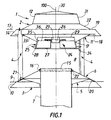
- the device 1 comprises a lower element 3, an element higher 2; 4 association bodies in the form spacers of the lower 3 and upper 2 elements of way that they are spaced coaxially and opposite one on the other, which gives them a free passage 8 for gases or fumes.
- the free passage 8 in axial cross section has a shape general in convergent / divergent.
- the device includes in addition to a conduit 7 for gases or fumes passing through the lower element 3 and opening through its downstream opening 15 in passage 8 (the qualifier "downstream" means by relation to the normal direction of gas or smoke circulation when rejected by the device).
- the duct 7 has a certain axial length. He is destined to be connected to the chimney by means of flanges or other.
- the device finally comprises a centrifugal impeller with blades radial.
- the lower element 3 comprises a bottom 5 lower and a lower hat 6, each shaped general frustoconical. Bottom 5 and hat lower 6 are crossed coaxially by the pipe 7 having a given diameter d. Pipe 7 leads to one of its ends 15, bottom hat side 6, in space 8 between the two elements 2, 3. The other end of the pipe 7 is fixed to the inlet of the gaseous fluid, namely the fireplace. In the embodiment shown in the Figures 1 and 2, the pipe 7 has at its side end space 8 a radial annular projection 22 on which comes to lock in abutment the small base of the hat lower 6.
- the bottom bottom 5 and the bottom cap 6 are rigidly fixed to each other.
- the lower cap 6 is provided with an annular lip 10, adjoining a large common base 9, directed downward from said large base 9 and in line with the surface of the lower hat 6.
- the lower bottom 5 includes a peripheral crown 20 parallel to the frustoconical surface of the lower cap 6.
- the annular lip 10 comes in direct extension of the frustoconical surface of the hat lower 6 and the connecting spacers 4 rest on the frustoconical surface of the lower cap 6.
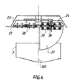
- each of the spacers 4 can, for example, be provided at its end lower, of a lower connecting tab 21 (figure 3). In a spacer service position, this lower tab 21 is parallel to, and in contact with and secured to the frustoconical surface of the lower cap 6 and extends in a tangential direction.
- the tab lower link 21 can be in one piece with the spacer, in another embodiment of the invention the lower leg 21 can be added to the end of the spacer 4.
- the cap lower 6 includes in its frustoconical surface axial peripheral bosses intended to receive the end of the lower element side 3 of the spacers 4.
- each boss comprises a transverse base in look of a transverse flat of the peripheral crown 20 of the lower bottom 5. Together they define a base transverse mounting and securing of the end lower element side 3 of a spacer 4 on the element lower 3.
- the upper element 2 comprises an upper cap 12 and an upper bottom 11. They are rigidly fixed one to the other by a large common base 13.
- the upper bottom 11 and the upper cap 12 each include a transverse peripheral crown 18, 19 opposite.
- These transverse peripheral rings 18, 19 define a transverse mounting and joining strip the end of the upper element side 2 of the spacers 4 on the upper element 2.
- each spacer 4 may, for example, have an upper tab of link, parallel to the transverse strip and extending in a tangential direction.
- the two forms of realization cited for the lower leg 21 are also applicable for the upper leg.
- the mounting of the upper base 11 and the upper cap 12 on the end, upper element side 2, spacers 4 can also be achieved, without day, by joining together the ends, on the side of the spacers 4, of the cap upper 12 and upper bottom 11.
- the upper cap 12 can also be provided with a peripheral annular lip 14, adjoining the large base 13, directed downward from the large base and into the extension of the surface of the upper cap 12.
- This peripheral annular lip 14 comes in extension of the peripheral crown 18 of the upper cap 12 and covering the peripheral ring 19 of the bottom higher 11.
- transverse peripheral rings 18 and 19 in look respectively are an extension of the large base of the first truncated cone 33 of the upper bottom 11 and in extension of the large base of the second truncated cone 32 upper cap 12.
- the upper bottom 11 has an axial cavity 25 open to space 8 housing the blades 24 of a turbine centrifugal.
- the blades 24 have a lower radial edge 27 flush with the base 28 lower of the axial cavity 25.
- the centrifugal turbine includes a stator 23 housed inside the cavity axial 25 and a rotor 26 also housed inside the axial cavity 25.
- the rotor 26 carries the radial blades 24, for example two, three, four or five.
- the upper cap 12 includes a 3G conical cap extended by its large base and coaxially by a first truncated cone 31, of reduced size, having its small common base with the large base of the cap 30.
- the first truncated cone 31 is itself extended coaxially by a second truncated cone 32 having its small common base with the large base of the first trunk of cone 31.
- the upper cap 12 includes a single conical cap - replacing the cone trunks 31 and 32- whose large base is common with the upper bottom 11.
- the frustoconical surface of the conical cap made for example with its large base a angle of the order of 22 °.
- the upper bottom 11 comprises a first trunk of cone 33 coaxial to upper cap 12 small base 17 space side 8.
- the small base 17 is suitable for accommodate the cavity or a cavity element 25 intended to house the blades 24.
- the cavity 25 has a frustoconical shape coaxial with the upper cap 12 and includes a large base 28 on the space side 8 and a small base 29 closed on the side top hat 12.
- the cavity element 25 projects in part from the upper bottom 11, in particular of the small base 17 of the first trunk of cone 33, towards space 8.
- the cavity or the cavity element 25 can be advantageously provided with an adjoining annular lip 34 at the peripheral base 28 and directed upwards.
- the small base 15 of the hat lower 6 includes an annular projection 16 of direction axial and height h.
- this axial annular projection 16 can be produced by the end 15 of the pipe 7 protruding from the small base of the lower cap 6 to space 8.
- the device 1 according to the invention is such that the maximum diameter D of the upper element 2 is substantially equal to the maximum diameter of the element lower 3.
- the dimensional ratio D / d is advantageously understood between 1.5 and 3.
- the dimensional ratio D / d is preferably substantially equal to 2.25.
- the dimensional ratio h / d (h being the height of the annular projection 16) is advantageously between 0.01 and 0.15.
- the dimensional ratio h / d is preferably substantially equal to 0.08.
- H be the minimum distance separating the two elements upper and lower (i.e. in the embodiment shown in Figure 2, the distance separating the end 15 of the large base 28 from the element 25), the dimensional ratio H / d is advantageously between 0.25 and 1.2.
- the report dimensional H / d is preferably substantially equal to 0.7.
- the angle a is advantageously between 15 ° and 45 ° and preferably substantially equal to 30 °.
- angles b and g are advantageously between 0 ° and 30 ° and preferably equal to 22 °.
- the angle d is advantageously between 0 ° and 30 ° and preferably substantially equal to 22 °.
- d 2 be the diameter of the small closed base 29 of the cavity 25, the dimensional ratio d 2 / d is advantageously between 0.8 and 2 and preferably substantially equal to 1.12.
- d 3 be the diameter of the large open base 28 of the cavity 25, the dimensional ratio d 3 / d is advantageously between 1 and 2.40 and preferably substantially equal to 1.31.
- d4 be the axial height of the axial cavity 25, the dimensional ratio d 4 / d is advantageously between 0.2 and 0.5 and preferably substantially equal to 0.28.
- the cavity 25 projects from the small base 17 of the first truncated cone 33 from the upper bottom 11 to the space 8, with a value between half and all of its axial height d 4 .
- the projecting part of the cavity 25 is substantially equal to 0.18 x d.
- the angle m is advantageously between 45 ° and 90 ° and preferably substantially equal to 75 °.
- the frustoconical surface of the first truncated cone 31 of the upper cap 12 makes an angle of the order of 60 ° more or less 10 ° with its large base.
- the conical surface of the conical cap 30 of the hat upper 12 advantageously makes an angle of the order of 12 ° more or less 5 ° with its large base.
- the distance between the small closed base 29 of the cavity 25 from the top of the conical cap 30 is advantageously and preferably of the order of 0.8 x d.
- the annular lip 34 adjoining the base 28 forms an angle of the order of 22 ° plus or minus 10 ° with the base 28 and a a width of the order of 0.1 x d.
- the device comprises at least two, in particular three connecting struts 4 arranged every 120 ° at its periphery.
- the spacers 4 are flat in shape with rounded edges, of radial length t 3 and of width e 3 .
- the dimensional ratio t 3 / d is advantageously between 0.04 and 0.07 and preferably substantially equal to 0.05.
- the dimensional ratio e 3 / t 3 is advantageously between 0.02 and 0.5.
- the spacers 4 have over most of their axial length - along axis 100 - a boss, arranged substantially at center of the spacers 4 and substantially parallel to axis 100.
- the region of the spacers 4 located on either side of this boss can then be reduced in thickness and not consist than a thin plate.
- the angle l is advantageously between 45 ° and 70 ° and preferably substantially equal to 60 °.
- the transverse peripheral rings 18 defining the transverse mounting and securing band of the end of the upper element side 2 of the spacers on the upper element 2 have a radial width substantially equal to the radial length t 3 of said spacers 4.
- the device according to the invention may further comprise a mesh element (not shown), of cylindrical shape coaxial with, and extending between the upper 2 and lower elements 3.
- This mesh element of cylindrical shape has a diameter at least greater than the diameter d 3 of the large open base 29 of the cavity 25 increased by the annular crown 34.
- this mesh element comprises meshes of 20 mm x 20 mm to more or less 2mm.
- the element lower 3 comprises a part 44 of general shape frustoconical whose small base 45, upper, where is finds the space 8, is turned towards the upper element 2 while the large base 46, lower, faces the opposite of the upper element 2.
- the diameter of the large base 46 is of the order of 1.6 to 2.5 times the diameter of the small base 45.
- the lower element 3 is placed opposite the element upper 2, being removed from the latter, the elements upper (2) and lower (3) being secured one with the other by means of spacers 4.
- spacers extend substantially parallel to axis 100.
- the small base 45 of the lower element 3 can be surmounted by a lip 47, of section substantially circular.
- the height of the lip 47 -counted parallel to the axis 100- is around 0.01 to 0.02 times the diameter of the small base 45.
- the height -counted along the axis 100- between the free peripheral edge of lip 47 and upper bottom 11 is of the order of 0.45 to 0.8 times the diameter of the small base 45.
- the upper bottom 11 of the upper element 2 is presented in the form of a flattened cup 48.
- This cup 48 is generally circular in shape.
- the cup 48 includes a central part 49, transverse, axially offset from the part remaining annular outer 50.
- the outside diameter of the cup 48 is equal or close the outside diameter of the lower element 3 defined by the large base 9.
- the diameter of the central part 49 is equal to or close to the diameter of the open space 8. It is, in the modes of represented achievement, between 0.8 and 1.25 times the diameter of the small base 45.
- the diameter of the central part 49 is, in the achievement considered, between 0.4 and 0.6 times approximately the outside diameter of the cup 48.
- the diameter of the central part 49 is the order of half the outside diameter of the cup 48.
- the axial offset of the central part 49 relative to the annular outer part 50 - along axis 100 - is the order of a tenth of the diameter of the central part 49, and preferably of the order of 0.15 to 0.5 times the diameter of the small base 45.
- the central transverse part 49 is flat or substantially flat, as is the exterior ring finger 50.
- the central part 49 is connected to the external part 50 by a connecting wall 51 of general shape frustoconical, inclined relative to the axis 100.
- This connecting wall 51 is located on the side of the central part 49 and its large diameter of the side of the annular outer part 50.
- the angle of inclination of the connecting wall 51 on axis 100 is between 15 ° and 45 °.
- this angle is around 20 °.
- the cup 48 comprises in the embodiment shown, a outer edge 52 falling towards a transverse median plane, passing through the middle part of the lower element 3.
- the axial length of the falling outer edge 52 is the order of one third or two thirds of the axial offset of the central part 49 relative to the external part ring finger 50.
- the angle of inclination of the outer edge falling 52 on axis 100 can be of the same order of magnitude as that of the connection wall 51.
- the cavity 25 formed by the central part 49 and the wall connection 51 allows the housing of a turbine, represented schematically by the reference 53, fixed to the cup 48.
- the upper element 2 comprises a protective cover 54.
- This protective cover 54 is fixed to the cup 48, of the side opposite the lower element 3.
- Such a cover 54 has a generally conical shape or frustoconical with, in the latter case, a wall upper transverse 55.
- Such a cover 54 can be fixed to the external part annular 50 in the vicinity of the falling edge 52.
- An opening 56 can be provided between the cover 54 and the part outer annular 50 so as to allow the air circulation inside the cover 54.
- the cover 54 can be fixed on the connection wall 51, optionally by providing an opening between the cover 54 and the wall 51.
- the cover 54 can be fixed on the central part 49, optionally by providing an opening between the cover 54 and the central part 49, by means of pads substantially parallel to axis 100.
- the cover 54 does not occupy the entire surface of the dish 48.
- an opening 57 is provided in the upper wall 55 of the cover 54.
- the wall 55 is surmounted by a cap 58, of shape general conical.
- the base 59 of the hat 58 is fixed to the wall 55 with a space 60 between them for the evacuation of air from opening 57.
- the cavity 25 projects in part from the small base 17 from the first truncated cone 33 from the upper bottom 11 towards space 8.
- the large base 28 of the cavity 25 can also be arranged substantially in the same horizontal plane as the upper bottom 11 -or, in the embodiment of the Figure 6 of the cup 48- of the upper element 2, the cavity 25 being in this case fully integrated in the upper element 2.
- the small base 29 of the cavity 25 is substantially in the same plane as the bottom upper 11 -or that the cup 48- of the upper element 2, the cavity 25 then being placed outside of the upper element 2.
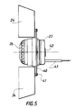
- the device according to the invention comprises a turbine centrifugal comprising a stator 23 provided on one of its faces of a conventional fastening means 42 in itself.
- This means 42 is intended for fixing the turbine in the axial cavity 25.
- the centrifugal turbine also includes a rotor 26 on which is mounted, on the side of the stator 23, a flange 40 allowing the blades 24 to be fixed by means 41 classic in itself, for example screwing.
- the turbine comprises, on the stator 23 side, means for electrical connection 43 connected to a command (not shown) to activate or deactivate it turbine operation.
- the distal 35 and upper radial 36 edges of the blades 24, mounted via the flange 40, can advantageously match the surface of the cavity 25.
- the rotor 26 is provided with at least one fixing part blades 24, replacing the flange 40 of FIG. 5.
- This fixing piece is fixed to the rotor 26, by example by a screw 62, positioned along the axis of rotation of the rotor 26.
- the fixing part consists for example of an oblong bar 61 conforming substantially to the shape external of the rotor 26 on either side of the screw 62 and is extending towards the stator 23.
- a blade 24 is fixed, for example by screwing, directly or by means of a plate 63 added.
- one or more can be provided multiple bars 61.
- the fixing part consists of a hollow cap covering the rotor 26 being fixed thereon by a screw positioned along the axis of rotation of the rotor 26.
- the lower radial edges 27 of the blades 24 are extended by blade elements 37 articulated in rotation around of said radial edges 27. This rotation is ensured by one or more hinges 39. These blade elements 37 are articulated in rotation between a first position at rest where the blade elements 37 are substantially perpendicular to the blades 24 when the turbine is not activated, and a second active position where each element blade 37 is substantially in the same plane as the blade 24 associated when the turbine is activated.
- the blade elements 37 are forced into the rest position by an elastic element 38.
- the transition from the rest position to the active position is due to the inertial and centrifugal forces induced by the rotation imparted by the turbine to the blades 24 and to the blade elements 37.
- the device according to the invention comprises two large blades 24 crossing on axis 100 so as to create four half-blades.
- the two blades 24 intersect at an angle law.
- each half-blade includes a blade element 37 in a quarter circle.
- the blade elements 37 are perpendicular to the half-blades and form in combination a cover closing the lower base 28 of the cavity 25. In this way, in the rest position, that is to say when the engine is not activated, the performance of the device are not disturbed by the presence of blades 24, these being masked by the blade elements 37.
Abstract
Description
- la figure 1 est une vue schématique, en coupe verticale diamétrale d'un mode de réalisation du dispositif selon la présente invention ;
- la figure 2 est la même vue schématique que la figure 1 présentant des références dimensionnelles ;
- la figure 3 est une représentation schématique, vue de dessus, du chapeau inférieur du dispositif de la figure 1 ;
- la figure 4 est une vue de détail d'une partie du dispositif avec éléments de pales mobiles ;
- la figure 5 est une vue schématique, de côté, d'une première turbine centrifuge utilisée dans le dispositif de l'invention ;
- la figure 6 est une vue schématique, en coupe verticale diamétrale, d'un autre mode de réalisation du dispositif de l'invention ;
- la figure 7 est une vue schématique, de côté, d'une autre turbine centrifuge utilisée dans le dispositif de l'invention.
| FOURCHETTE | VALEUR PREFEREE | |
| D/d | 1,5 - 3 | 2,25 |
| h/d | 0,01 - 0,15 | 0,08 |
| H/d | 0,25 - 1,2 | 0,7 |
| d2/d | 0,8 - 2 | 1,12 |
| d3/d | 1 - 2,40 | 1,31 |
| d4/d | 0,2 - 0,5 | 0,28 |
| t3/d | 0,04 - 0,07 | 0,05 |
| e3/t3 | 0,02 -0,5 | / |
| a | 15° - 45° | 30° |
| b | 0° - 30° | 22° |
| g | 0° - 30° | 22° |
| d | 0° - 30° | 22° |
| l | 45° - 70° | 60° |
| m | 45° - 90° | 75° |
Claims (34)
- Dispositif (1) mixte, statique/dynamique pour l'évacuation de fluide gazeux, notamment de gaz rejetés ou de fumées comprenant d'une part un élément supérieur (2) et un élément inférieur (3), superposés, coaxiaux, rigidement fixés l'un à l'autre par des entretoises (4) de liaison, l'élément inférieur comprenant un fond (5) inférieur et un chapeau (6) inférieur, traversés coaxialement par un tuyau (7) de diamètre donné d débouchant à l'une de ses extrémités, côté chapeau inférieur (6), dans l'espace (8) compris entre les deux éléments (2, 3), l'autre extrémité du tuyau (7) étant destinée à être fixée à l'arrivée des fluides gazeux, ledit fond (5) inférieur et ledit chapeau inférieur (6) étant rigidement fixés l'un à l'autre par leur grande base commune (9) ; l'élément supérieur (2) comprenant un fond supérieur (11) et un chapeau supérieur (12) ; et d'autre part une turbine centrifuge comprenant un moteur et au moins une pale (24),
le fond supérieur (11) présentant une cavité (25) axiale ouverte vers l'espace (8) abritant les pales (24), le moteur comprenant un stator (23) localisé à l'intérieur de la cavité axiale (25) et un rotor (26) muni d'au moins une pale (24), localisé dans la cavité axiale (25), le moteur étant dépourvu d'arbre moteur. - Dispositif selon la revendication 1, caractérisé en ce que la cavité (25) a une forme tronconique coaxiale au chapeau supérieur (12), de grande base (28) côté espace (8), de petite base (29) fermée.
- Dispositif selon la revendication 1 ou 2, caractérisé en ce que la cavité (25) saille en partie du fond supérieur (11) de l'élément supérieur (2) vers l'espace (8).
- Dispositif selon la revendication 1 ou 2, caractérisé en ce que la grande base (28) de la cavité (25) est disposée sensiblement dans le même plan que le fond supérieur (11) de l'élément supérieur (2), la cavité (25) étant alors intégrée à l'intérieur de l'élément supérieur (2), ou la petite base (29) de la cavité (25) est sensiblement dans le même plan que le fond supérieur (11) de l'élément supérieur (2), la cavité (25) étant alors placée à l'extérieur de l'élément supérieur (2).
- Dispositif selon la revendication 1 ou 2, caractérisé en ce que la cavité (25) occupe une position intermédiaire entre une position située à l'intérieur de l'élément supérieur (2) et une position située à l'extérieur de l'élément supérieur (2).
- Dispositif selon l'une quelconque des revendications 1 à 5, caractérisé en ce que les pales (24) ont un bord radial (27) inférieur affleurant la base inférieure (28) de la cavité axiale (25).
- Dispositif selon l'une quelconque des revendications 1 à 6, caractérisé en ce que le chapeau supérieur (12) comprend une calotte conique (30), la grande base de la calotte conique (30) étant prolongée coaxialement par un premier tronc de cône (31), de dimension réduite, de petite base commune avec la grande base de la calotte (30), le premier tronc de cône (31) étant lui-même prolongé coaxialement par un deuxième tronc de cône (32) de petite base commune avec la grande base du premier tronc de cône (31).
- Dispositif selon l'une quelconque des revendications 1 à 7, caractérisé en ce que le fond supérieur (11) comprend un premier tronc de cône (33) coaxial au chapeau supérieur (12) de petite base (17) côté espace (8), ladite petite base (17) étant adaptée pour accueillir la cavité (25) destinée à abriter les pales (24).
- Dispositif selon l'une quelconque des revendications 1 à 8, caractérisé en ce que le chapeau supérieur (12) est pourvu d'une lèvre annulaire (14), périphérique, dirigée vers le bas à partir de la grande base (13) et dans le prolongement de la surface du chapeau supérieur (12).
- Dispositif selon l'une quelconque des revendications 1 à 9, caractérisé en ce que le fond supérieur (11) et le chapeau supérieur (12) comprennent chacun une couronne périphérique transversale (18, 19) en regard, définissant une bande transversale de montage et de solidarisation de l'extrémité côté élément supérieur (2) des entretoises (4) sur ledit élément supérieur (2), la lèvre (14) annulaire venant en prolongement de la couronne périphérique (18) du chapeau supérieur (12) et en recouvrement de la couronne périphérique (19) du fond supérieur (11), les couronnes périphériques transversales (18, 19) en regard venant respectivement en prolongement de la grande base du premier tronc de cône (33) du fond supérieur (11) et en prolongement de la grande base du deuxième tronc de cône (32) du chapeau supérieur (12).
- Dispositif selon l'une quelconque des revendications 1 à 10, caractérisé en ce que le chapeau supérieur (12) comprend une calotte conique unique dont la grande base est commune avec le fond supérieur (11), la surface tronconique de la calotte conique unique faisant par exemple avec sa grande base un angle de l'ordre de 22°.
- Dispositif selon l'une quelconque des revendications 1 à 6, caractérisé en ce que l'élément supérieur (2) comprend un fond supérieur (11) se présentant sous la forme d'une coupelle aplatie (48), de forme générale circulaire, la coupelle (48) comprenant une partie centrale (49), transversale, décalée axialement par rapport à la partie restante extérieure annulaire (50), la partie centrale (49) étant plane ou sensiblement plane et étant raccordée à la partie extérieure annulaire (50) par une paroi de raccordement (51) de forme générale tronconique.
- Dispositif selon l'une quelconque des revendications 1 à 11, caractérisé en ce que le fond (15) inférieur et le chapeau inférieur (6) sont chacun de forme tronconique et en ce que le chapeau inférieur (6) est pourvu d'une lèvre annulaire (10), attenante à la grande base commune (9), dirigée vers le bas à partir de la grande base commune (9) et dans le prolongement de la surface du chapeau inférieur (6).
- Dispositif selon la revendication 13, caractérisé en ce que le fond inférieur (5) comprend une couronne périphérique (20) parallèle à la surface tronconique du chapeau inférieur (6).
- Dispositif selon l'une quelconque des revendications 1 à 6 et 12, caractérisé en ce que l'élément inférieur (3) comprend une pièce (44) de forme générale tronconique dont la petite base (45) supérieure, est tournée vers l'élément supérieur (2), tandis que la grande base (46) inférieure, est tournée vers l'opposé de l'élément supérieur (2).
- Dispositif selon la revendication 15, caractérisé en ce que la petite base (45) est surmontée d'une lèvre (47) de section sensiblement circulaire.
- Dispositif selon l'une quelconque des revendications 1 à 16, caractérisé en ce que chacune des entretoises (4) en position de service comprend à son extrémité inférieure une patte de liaison inférieure (21) parallèle à, et au contact, et solidaire de la surface tronconique du chapeau inférieur (6), et s'étendant dans une direction tangentielle à l'axe (100) du dispositif.
- Dispositif selon la revendication 17, caractérisé en ce que les entretoises (4) comportent sur la majeure partie de leur longueur axiale -suivant l'axe (100)- un bossage, disposé sensiblement au centre des entretoises (4) et sensiblement parallèlement à l'axe (100), la région des entretoises (4) située de part et d'autre du bossage étant d'épaisseur réduite.
- Dispositif selon l'une quelconque des revendications 1 à 18, caractérisé en ce que le chapeau inférieur (6) comprend, au niveau de sa petite base (15), une saillie annulaire (16) de direction axiale et de hauteur h, le rapport dimensionnel h/d étant compris entre 0,01 et 0,15 et préférentiellement sensiblement égal à 0,08 et/ou en ce que l'angle 1 que font les lèvres annulaires (10, 14) avec les grandes bases (9, 13) est compris entre 45° et 70° et préférentiellement sensiblement égal à 60°.
- Dispositif selon l'une quelconque des revendications 1 à 19, caractérisé en ce que le diamètre maximal D de l'élément supérieur (2) est sensiblement égal au diamètre maximal de l'élément inférieur (3), et en ce que le rapport dimensionnel D/d est compris entre 1,5 et 3 et préférentiellement sensiblement égal à 2,25.
- Dispositif selon l'une quelconque des revendications 1 à 20, caractérisé en ce que H étant la distance minimale séparant les deux éléments supérieur (2) et inférieur (3), le rapport dimensionnel H/d est compris entre 0,25 et 1,2 et préférentiellement sensiblement égal à 0,7.
- Dispositif selon l'une quelconque des revendications 1 à 21, caractérisé en ce que l'angle a que fait la surface tronconique du chapeau inférieur (6) avec sa grande base (9) est compris entre 15° et 45° et préférentiellement sensiblement égal à 30°.
- Dispositif selon l'une quelconque des revendications 1 à 22, caractérisé en ce que l'angle b et/ou l'angle g et/ou l'angle d que font respectivement la surface tronconique du fond inférieur (5), la surface tronconique du deuxième tronc de cône (32), la surface du premier tronc de cône (33) du fond supérieur (11) avec leur grande base respective est/sont comprise(s) entre 0° et 30° et préférentiellement sensiblement égal/égaux à 22°.
- Dispositif selon l'une quelconque des revendications 1 à 23, caractérisé en ce que d2 étant le diamètre de la petite base fermée (29) de la cavité (25), le rapport dimensionnel d2/d est compris entre 0,8 et 2 et préférentiellement sensiblement égal à 1,12 et/ou en ce que d3 étant le diamètre de la grande base ouverte (28) de la cavité (25), le rapport dimensionnel d3/d est compris entre 1 et 2,40 et préférentiellement sensiblement égal à 1,31 et/ou en ce que d4 étant la hauteur axiale de la cavité axiale (25), le rapport dimensionnel d4/d est compris entre 0,2 et 0,5 et préférentiellement sensiblement égal à 0,28.
- Dispositif selon l'une quelconque des revendications 1 à 24, caractérisé en ce que la cavité (25) saille de la petite base (17) vers l'espace (8) entre la moitié et la totalité de sa hauteur axiale et préférentiellement saille d'une distance sensiblement égale à 0,18 x d, et en ce que l'angle m que fait la surface tronconique de la cavité (25) avec sa grande base (28) est compris entre 45° et 90° et préférentiellement sensiblement égal à 75°.
- Dispositif selon l'une quelconque des revendications 7 à 25, caractérisé en ce que la surface tronconique du premier tronc de cône (31) du chapeau supérieur (12) fait un angle de l'ordre de 60° plus ou moins 10° avec sa grande base, et/ou en ce que la surface conique de la calotte conique (30) fait un angle de l'ordre de 12° plus ou moins 5° avec sa grande base.
- Dispositif selon l'une quelconque des revendications 1 à 26, caractérisé en ce que la distance séparant la petite base (29) fermée de la cavité (25) du sommet de la calotte conique (30) est de l'ordre de 0,8 x d.
- Dispositif selon l'une quelconque des revendications 1 à 27, caractérisé en ce que la cavité (25) axiale est pourvue d'une lèvre annulaire (34) attenante à la base (28), périphérique et dirigée vers le haut faisant un angle de l'ordre de 22° plus ou moins 10° avec la base (28) et ayant une largeur de l'ordre de 0,1 d.
- Dispositif selon l'une quelconque des revendications 1 à 28, caractérisé en ce qu'il comprend au moins deux entretoises (4) disposées à la périphérie du dispositif, les entretoises (4) étant de forme plate à bords arrondis, de longueur radiale t3 et d'épaisseur e3, le rapport dimensionnel t3/d étant compris entre 0,04 et 0,07 et préférentiellement sensiblement égal à 0,05, et le rapport dimensionnel e3/t3 étant compris entre 0,02 et 0,5.
- Dispositif selon l'une quelconque des revendication 1 à 29, caractérisé en ce que la turbine comporte un stator (23) muni sur l'une de ses faces d'un moyen de fixation (42), la turbine comprenant de plus un rotor (26) sur lequel est montée, du côté du stator (23), une flasque (40) permettant la fixation des pales (24).
- Dispositif selon l'une quelconque des revendications 1 à 29, caractérisé en ce que le rotor (26) est muni d'au moins une pièce de fixation des pales (24), fixée sur le rotor (26), par exemple par une vis (62) positionnée selon l'axe de rotation du rotor (26) ; la pièce de fixation consistant en une barre oblongue (61) épousant sensiblement la forme externe du rotor (26) de part et d'autre de la vis (62) et se prolongeant vers le stator (23), une pale (24) étant fixée à chaque extrémité de la barre (61), ou la pièce de fixation consistant en une calotte creuse recouvrant le rotor (26) en étant fixée sur celui-ci par une vis positionnée selon l'axe de rotation du rotor (26), au moins une pale (24) étant fixée sur la calotte creuse.
- Dispositif selon l'une quelconque des revendications 1 à 31, caractérisé en ce que les bords radiaux inférieurs (27) des pales (24) sont prolongés par des éléments de pales (37) articulés en rotation autour desdits bords radiaux (27) entre une première position au repos où les éléments de pales (37) sont sensiblement perpendiculaires aux pales (24) lorsque la turbine n'est pas active, et une deuxième position active où chaque élément de pales (37) est sensiblement dans le même plan que la pale (24) associée lorsque la turbine est en action.
- Dispositif selon la revendication 32, caractérisé en ce que les éléments de pales sont forcés dans la position de repos par un élément élastique (38), le passage de la position de repos à la position active étant dû aux forces d'inertie et centrifuge induite par la rotation imprimée par la turbine aux pales (24) et aux éléments de pales (37).
- Dispositif selon l'une quelconque des revendications 1 à 33, caractérisé en ce qu'il comporte deux grandes pales (24) se croisant sur l'axe (100) de manière à créer quatre demi-pales, et en ce que les deux pales (24) se coupant à angle droit, chaque demi-pale comprend un élément de pale (37) en quart de cercle, de telle manière qu'en position de repos, les éléments de pales (37) forment en combinaison un couvercle fermant la base inférieure (28) de la cavité (25).
Applications Claiming Priority (2)
| Application Number | Priority Date | Filing Date | Title |
|---|---|---|---|
| FR9809163 | 1998-07-17 | ||
| FR9809163A FR2781278B1 (fr) | 1998-07-17 | 1998-07-17 | Dispositif mixte, statique/dynamique pour l'evacuation de fluides gazeux |
Publications (2)
| Publication Number | Publication Date |
|---|---|
| EP0972991A1 true EP0972991A1 (fr) | 2000-01-19 |
| EP0972991B1 EP0972991B1 (fr) | 2003-05-21 |
Family
ID=9528729
Family Applications (1)
| Application Number | Title | Priority Date | Filing Date |
|---|---|---|---|
| EP99401800A Expired - Lifetime EP0972991B1 (fr) | 1998-07-17 | 1999-07-16 | Dispositif mixte, statique/dynamique pour l'evacuation de fluides gazeux |
Country Status (9)
| Country | Link |
|---|---|
| EP (1) | EP0972991B1 (fr) |
| AT (1) | ATE241113T1 (fr) |
| CZ (1) | CZ300729B6 (fr) |
| DE (1) | DE69908031D1 (fr) |
| FR (1) | FR2781278B1 (fr) |
| HU (1) | HU227786B1 (fr) |
| PL (1) | PL193456B1 (fr) |
| RU (1) | RU2222753C2 (fr) |
| WO (1) | WO2000004323A1 (fr) |
Cited By (8)
| Publication number | Priority date | Publication date | Assignee | Title |
|---|---|---|---|---|
| EP1120610A2 (fr) * | 2000-01-28 | 2001-08-01 | Holland Heating B.V. | Ensemble pour un ventilateur de toit |
| FR2842585A1 (fr) | 2002-07-17 | 2004-01-23 | Invent Or | Dispositif d'extraction de gaz stato-mecanique |
| WO2006004450A2 (fr) * | 2004-07-06 | 2006-01-12 | PRZEDSIEBIORSTWO USLUGOWO-PRODUKCYJNE I WDRAZANIA POSTEPU TECHNICZNEGO 'UNIVERSAL'Sp.z o.o. | Bouchon de ventilation hybride |
| FR2926129A1 (fr) * | 2008-01-03 | 2009-07-10 | Vti Sarl | Dispositif et procede de regulation d'un ventilateur et extracteur hybride d'air vicie equipe d'un tel dispositif |
| EP2853830A1 (fr) | 2013-06-27 | 2015-04-01 | André Amphoux | Module de système de ventilation et système de ventilation de bâtiment pouvant être piloté à distance via l'Internet |
| FR3019273A1 (fr) * | 2014-04-01 | 2015-10-02 | Bosch Gmbh Robert | Installation de chauffage monobloc a ventilateur deporte |
| EP3477215A1 (fr) | 2017-10-24 | 2019-05-01 | André Amphoux | Système de gestion d'unités de ventilation |
| CN110252067A (zh) * | 2019-07-11 | 2019-09-20 | 陈柏华 | 一种电厂排放的粉尘回收装置 |
Families Citing this family (2)
| Publication number | Priority date | Publication date | Assignee | Title |
|---|---|---|---|---|
| ES2306596B1 (es) * | 2007-02-15 | 2009-10-27 | Sistemas Shunt De Baleares, S.L. | Aspirador aplicable a la boca de salida en conductos de ventilacion. |
| RU2507449C2 (ru) * | 2012-04-24 | 2014-02-20 | Леонид Николаевич Парфенов | Факельная свечевая установка |
Citations (7)
| Publication number | Priority date | Publication date | Assignee | Title |
|---|---|---|---|---|
| FR404895A (fr) * | 1908-07-09 | 1909-12-14 | Karl Maxaner | Ventilateur centrifuge à entrée axiale et sortie radiale de l'air |
| FR2092177A5 (fr) * | 1970-05-05 | 1971-01-21 | Technicair Sa | |
| FR2209410A5 (fr) * | 1972-11-03 | 1974-06-28 | Technicair Sa | |
| DE2557762A1 (de) * | 1975-12-20 | 1977-06-30 | Buettner Schilde Haas Ag | Dachluefter fuer waagerechten ausblas |
| EP0416999A1 (fr) * | 1989-09-06 | 1991-03-13 | André Amphoux | Dispositif d'aspiration de gaz |
| FR2709534A1 (fr) * | 1993-09-03 | 1995-03-10 | Amphoux Andre | Dispositif statique/dynamique pour l'évacuation de fluide gazeux. |
| FR2711770A1 (fr) * | 1993-10-25 | 1995-05-05 | Zaniewski Michel | Perfectionnements aux dispositifs modulaires permettant l'assemblage d'appareils d'extraction des fumées ou d'aération des locaux. |
Family Cites Families (1)
| Publication number | Priority date | Publication date | Assignee | Title |
|---|---|---|---|---|
| FR1403955A (fr) | 1964-06-08 | 1965-06-25 | Aspirateur statico-dynamique de fluides gazeux |
-
1998
- 1998-07-17 FR FR9809163A patent/FR2781278B1/fr not_active Expired - Lifetime
-
1999
- 1999-07-16 DE DE69908031T patent/DE69908031D1/de not_active Expired - Lifetime
- 1999-07-16 HU HU0103179A patent/HU227786B1/hu not_active IP Right Cessation
- 1999-07-16 EP EP99401800A patent/EP0972991B1/fr not_active Expired - Lifetime
- 1999-07-16 WO PCT/FR1999/001742 patent/WO2000004323A1/fr active Application Filing
- 1999-07-16 RU RU2001101904/06A patent/RU2222753C2/ru active
- 1999-07-16 AT AT99401800T patent/ATE241113T1/de not_active IP Right Cessation
- 1999-07-16 PL PL99345674A patent/PL193456B1/pl unknown
- 1999-07-16 CZ CZ20010218A patent/CZ300729B6/cs not_active IP Right Cessation
Patent Citations (7)
| Publication number | Priority date | Publication date | Assignee | Title |
|---|---|---|---|---|
| FR404895A (fr) * | 1908-07-09 | 1909-12-14 | Karl Maxaner | Ventilateur centrifuge à entrée axiale et sortie radiale de l'air |
| FR2092177A5 (fr) * | 1970-05-05 | 1971-01-21 | Technicair Sa | |
| FR2209410A5 (fr) * | 1972-11-03 | 1974-06-28 | Technicair Sa | |
| DE2557762A1 (de) * | 1975-12-20 | 1977-06-30 | Buettner Schilde Haas Ag | Dachluefter fuer waagerechten ausblas |
| EP0416999A1 (fr) * | 1989-09-06 | 1991-03-13 | André Amphoux | Dispositif d'aspiration de gaz |
| FR2709534A1 (fr) * | 1993-09-03 | 1995-03-10 | Amphoux Andre | Dispositif statique/dynamique pour l'évacuation de fluide gazeux. |
| FR2711770A1 (fr) * | 1993-10-25 | 1995-05-05 | Zaniewski Michel | Perfectionnements aux dispositifs modulaires permettant l'assemblage d'appareils d'extraction des fumées ou d'aération des locaux. |
Cited By (11)
| Publication number | Priority date | Publication date | Assignee | Title |
|---|---|---|---|---|
| EP1120610A2 (fr) * | 2000-01-28 | 2001-08-01 | Holland Heating B.V. | Ensemble pour un ventilateur de toit |
| EP1120610A3 (fr) * | 2000-01-28 | 2002-11-06 | Holland Heating B.V. | Ensemble pour un ventilateur de toit |
| FR2842585A1 (fr) | 2002-07-17 | 2004-01-23 | Invent Or | Dispositif d'extraction de gaz stato-mecanique |
| WO2006004450A2 (fr) * | 2004-07-06 | 2006-01-12 | PRZEDSIEBIORSTWO USLUGOWO-PRODUKCYJNE I WDRAZANIA POSTEPU TECHNICZNEGO 'UNIVERSAL'Sp.z o.o. | Bouchon de ventilation hybride |
| WO2006004450A3 (fr) * | 2004-07-06 | 2007-05-03 | Przed Uslugowo Prod I Wdrazani | Bouchon de ventilation hybride |
| FR2926129A1 (fr) * | 2008-01-03 | 2009-07-10 | Vti Sarl | Dispositif et procede de regulation d'un ventilateur et extracteur hybride d'air vicie equipe d'un tel dispositif |
| EP2853830A1 (fr) | 2013-06-27 | 2015-04-01 | André Amphoux | Module de système de ventilation et système de ventilation de bâtiment pouvant être piloté à distance via l'Internet |
| FR3019273A1 (fr) * | 2014-04-01 | 2015-10-02 | Bosch Gmbh Robert | Installation de chauffage monobloc a ventilateur deporte |
| EP2937643A1 (fr) * | 2014-04-01 | 2015-10-28 | Robert Bosch GmbH | Installation de chauffage monobloc comportant un ventilateur déporté |
| EP3477215A1 (fr) | 2017-10-24 | 2019-05-01 | André Amphoux | Système de gestion d'unités de ventilation |
| CN110252067A (zh) * | 2019-07-11 | 2019-09-20 | 陈柏华 | 一种电厂排放的粉尘回收装置 |
Also Published As
| Publication number | Publication date |
|---|---|
| EP0972991B1 (fr) | 2003-05-21 |
| WO2000004323A1 (fr) | 2000-01-27 |
| CZ2001218A3 (cs) | 2002-02-13 |
| RU2222753C2 (ru) | 2004-01-27 |
| FR2781278B1 (fr) | 2000-09-29 |
| HU227786B1 (en) | 2012-02-28 |
| HUP0103179A3 (en) | 2002-03-28 |
| HUP0103179A2 (hu) | 2001-12-28 |
| FR2781278A1 (fr) | 2000-01-21 |
| CZ300729B6 (cs) | 2009-07-29 |
| ATE241113T1 (de) | 2003-06-15 |
| PL193456B1 (pl) | 2007-02-28 |
| PL345674A1 (en) | 2002-01-02 |
| DE69908031D1 (de) | 2003-06-26 |
Similar Documents
| Publication | Publication Date | Title |
|---|---|---|
| EP0641972B1 (fr) | Dispositif statique/dynamique pour l'évacuation de fluide gazeux | |
| CA2117983C (fr) | Dispositif modulaire permettant l'assemblage d'appareils d'extraction des fumees ou d'aeration des locaux | |
| EP0972991B1 (fr) | Dispositif mixte, statique/dynamique pour l'evacuation de fluides gazeux | |
| EP0641973B1 (fr) | Dispositif pour l'évacuation de fluide gazeux | |
| WO2010149894A1 (fr) | Dispositif d'eolienne de toiture | |
| EP0840070B1 (fr) | Extracteur d'air | |
| FR2782781A1 (fr) | Dispositif de securite pour systemes d'evacuation de fluides gazeux | |
| FR2842585A1 (fr) | Dispositif d'extraction de gaz stato-mecanique | |
| EP1413827A1 (fr) | Extracteur statique antireflueur pour fumées | |
| FR2543265A1 (fr) | Dispositif modulaire de protection de cheminee participant a l'extraction des fumees et utilise comme registre | |
| EP1286118B1 (fr) | Appareil de cuisson à gaz avec détrompage de positionnement de la tête de brûleur | |
| FR2713318A1 (fr) | Entrée d'air autoréglable, antiretour, acoustique à rouleau; installation comprenant une telle entrée d'air. | |
| FR2890433A1 (fr) | Aspirateur eolien a vortex interne vertical | |
| EP2513472B1 (fr) | Element de rotor pour systeme de production d'energie et systeme de production d'energie l'utilisant | |
| FR2855842A1 (fr) | Exutoire de fumees a haute performance aeraulique, specifiquement adapte pour des voutes de toitures de constructions ou de batiments | |
| EP0421841A1 (fr) | Dispositif pour le passage d'air et installation comportant un tel dispositif | |
| FR3016430B1 (fr) | Extracteur statique pour conduit d’evacuation d’air ou d’aeration | |
| FR2844580A1 (fr) | Dispositif aspirateur statique pour extraction de fumees | |
| FR2831945A1 (fr) | Chapeau de cheminee. | |
| FR2758177A1 (fr) | Aspirateur statique antirefouleur | |
| EP0834697A1 (fr) | Extracteur statique pour conduit de ventilation ou de fumée | |
| FR2614675A1 (fr) | Mitre de cheminee prefabriquee | |
| BE386290A (fr) | ||
| FR2799530A1 (fr) | Appareil d'extraction d'air et/ou de fumees equipe d'une grille protectrice | |
| FR2859271A1 (fr) | Dispositif aspirateur statique a venturi oriente par un element de type girouette pour extraction de fumees |
Legal Events
| Date | Code | Title | Description |
|---|---|---|---|
| PUAI | Public reference made under article 153(3) epc to a published international application that has entered the european phase |
Free format text: ORIGINAL CODE: 0009012 |
|
| AK | Designated contracting states |
Kind code of ref document: A1 Designated state(s): AT BE CH CY DE DK ES FI FR GB GR IE IT LI LU MC NL PT SE |
|
| AX | Request for extension of the european patent |
Free format text: AL;LT;LV;MK;RO PAYMENT 19990730;SI PAYMENT 19990730 |
|
| 17P | Request for examination filed |
Effective date: 20000202 |
|
| AKX | Designation fees paid |
Free format text: AT BE CH CY DE DK ES FI FR GB GR IE IT LI LU MC NL PT SE |
|
| AXX | Extension fees paid |
Free format text: RO PAYMENT 19990730;SI PAYMENT 19990730 |
|
| GRAH | Despatch of communication of intention to grant a patent |
Free format text: ORIGINAL CODE: EPIDOS IGRA |
|
| GRAH | Despatch of communication of intention to grant a patent |
Free format text: ORIGINAL CODE: EPIDOS IGRA |
|
| GRAA | (expected) grant |
Free format text: ORIGINAL CODE: 0009210 |
|
| AK | Designated contracting states |
Designated state(s): AT BE CH CY DE DK ES FI FR GB GR IE IT LI LU MC NL PT SE |
|
| AX | Request for extension of the european patent |
Extension state: RO SI |
|
| PG25 | Lapsed in a contracting state [announced via postgrant information from national office to epo] |
Ref country code: NL Free format text: LAPSE BECAUSE OF FAILURE TO SUBMIT A TRANSLATION OF THE DESCRIPTION OR TO PAY THE FEE WITHIN THE PRESCRIBED TIME-LIMIT Effective date: 20030521 Ref country code: IT Free format text: LAPSE BECAUSE OF FAILURE TO SUBMIT A TRANSLATION OF THE DESCRIPTION OR TO PAY THE FEE WITHIN THE PRE;WARNING: LAPSES OF ITALIAN PATENTS WITH EFFECTIVE DATE BEFORE 2007 MAY HAVE OCCURRED AT ANY TIME BEFORE 2007. THE CORRECT EFFECTIVE DATE MAY BE DIFFERENT FROM THE ONE RECORDED.SCRIBED TIME-LIMIT Effective date: 20030521 Ref country code: IE Free format text: LAPSE BECAUSE OF FAILURE TO SUBMIT A TRANSLATION OF THE DESCRIPTION OR TO PAY THE FEE WITHIN THE PRESCRIBED TIME-LIMIT Effective date: 20030521 Ref country code: GB Free format text: LAPSE BECAUSE OF FAILURE TO SUBMIT A TRANSLATION OF THE DESCRIPTION OR TO PAY THE FEE WITHIN THE PRESCRIBED TIME-LIMIT Effective date: 20030521 Ref country code: FI Free format text: LAPSE BECAUSE OF FAILURE TO SUBMIT A TRANSLATION OF THE DESCRIPTION OR TO PAY THE FEE WITHIN THE PRESCRIBED TIME-LIMIT Effective date: 20030521 Ref country code: AT Free format text: LAPSE BECAUSE OF FAILURE TO SUBMIT A TRANSLATION OF THE DESCRIPTION OR TO PAY THE FEE WITHIN THE PRESCRIBED TIME-LIMIT Effective date: 20030521 |
|
| REG | Reference to a national code |
Ref country code: GB Ref legal event code: FG4D Free format text: NOT ENGLISH |
|
| REG | Reference to a national code |
Ref country code: CH Ref legal event code: EP |
|
| REG | Reference to a national code |
Ref country code: IE Ref legal event code: FG4D Free format text: FRENCH |
|
| REF | Corresponds to: |
Ref document number: 69908031 Country of ref document: DE Date of ref document: 20030626 Kind code of ref document: P |
|
| PG25 | Lapsed in a contracting state [announced via postgrant information from national office to epo] |
Ref country code: LU Free format text: LAPSE BECAUSE OF NON-PAYMENT OF DUE FEES Effective date: 20030716 Ref country code: CY Free format text: LAPSE BECAUSE OF FAILURE TO SUBMIT A TRANSLATION OF THE DESCRIPTION OR TO PAY THE FEE WITHIN THE PRESCRIBED TIME-LIMIT Effective date: 20030716 |
|
| PG25 | Lapsed in a contracting state [announced via postgrant information from national office to epo] |
Ref country code: MC Free format text: LAPSE BECAUSE OF NON-PAYMENT OF DUE FEES Effective date: 20030731 Ref country code: LI Free format text: LAPSE BECAUSE OF NON-PAYMENT OF DUE FEES Effective date: 20030731 Ref country code: CH Free format text: LAPSE BECAUSE OF NON-PAYMENT OF DUE FEES Effective date: 20030731 Ref country code: BE Free format text: LAPSE BECAUSE OF NON-PAYMENT OF DUE FEES Effective date: 20030731 |
|
| PG25 | Lapsed in a contracting state [announced via postgrant information from national office to epo] |
Ref country code: SE Free format text: LAPSE BECAUSE OF FAILURE TO SUBMIT A TRANSLATION OF THE DESCRIPTION OR TO PAY THE FEE WITHIN THE PRESCRIBED TIME-LIMIT Effective date: 20030821 Ref country code: PT Free format text: LAPSE BECAUSE OF FAILURE TO SUBMIT A TRANSLATION OF THE DESCRIPTION OR TO PAY THE FEE WITHIN THE PRESCRIBED TIME-LIMIT Effective date: 20030821 Ref country code: GR Free format text: LAPSE BECAUSE OF FAILURE TO SUBMIT A TRANSLATION OF THE DESCRIPTION OR TO PAY THE FEE WITHIN THE PRESCRIBED TIME-LIMIT Effective date: 20030821 Ref country code: DK Free format text: LAPSE BECAUSE OF FAILURE TO SUBMIT A TRANSLATION OF THE DESCRIPTION OR TO PAY THE FEE WITHIN THE PRESCRIBED TIME-LIMIT Effective date: 20030821 |
|
| PG25 | Lapsed in a contracting state [announced via postgrant information from national office to epo] |
Ref country code: DE Free format text: LAPSE BECAUSE OF FAILURE TO SUBMIT A TRANSLATION OF THE DESCRIPTION OR TO PAY THE FEE WITHIN THE PRESCRIBED TIME-LIMIT Effective date: 20030822 |
|
| PG25 | Lapsed in a contracting state [announced via postgrant information from national office to epo] |
Ref country code: ES Free format text: LAPSE BECAUSE OF FAILURE TO SUBMIT A TRANSLATION OF THE DESCRIPTION OR TO PAY THE FEE WITHIN THE PRESCRIBED TIME-LIMIT Effective date: 20030901 |
|
| NLV1 | Nl: lapsed or annulled due to failure to fulfill the requirements of art. 29p and 29m of the patents act | ||
| GBV | Gb: ep patent (uk) treated as always having been void in accordance with gb section 77(7)/1977 [no translation filed] |
Effective date: 20030521 |
|
| REG | Reference to a national code |
Ref country code: IE Ref legal event code: FD4D Ref document number: 0972991E Country of ref document: IE |
|
| BERE | Be: lapsed |
Owner name: *AMPHOUX ANDRE Effective date: 20030731 |
|
| REG | Reference to a national code |
Ref country code: CH Ref legal event code: PL |
|
| PLBE | No opposition filed within time limit |
Free format text: ORIGINAL CODE: 0009261 |
|
| STAA | Information on the status of an ep patent application or granted ep patent |
Free format text: STATUS: NO OPPOSITION FILED WITHIN TIME LIMIT |
|
| 26N | No opposition filed |
Effective date: 20040224 |
|
| REG | Reference to a national code |
Ref country code: FR Ref legal event code: CL |
|
| REG | Reference to a national code |
Ref country code: FR Ref legal event code: PLFP Year of fee payment: 18 |
|
| REG | Reference to a national code |
Ref country code: FR Ref legal event code: PLFP Year of fee payment: 19 |
|
| REG | Reference to a national code |
Ref country code: FR Ref legal event code: PLFP Year of fee payment: 20 |
|
| PGFP | Annual fee paid to national office [announced via postgrant information from national office to epo] |
Ref country code: FR Payment date: 20180628 Year of fee payment: 20 |