EP0972137B1 - Steuerungssystem für einen hin und her gehenden zylinder - Google Patents
Steuerungssystem für einen hin und her gehenden zylinder Download PDFInfo
- Publication number
- EP0972137B1 EP0972137B1 EP97915496A EP97915496A EP0972137B1 EP 0972137 B1 EP0972137 B1 EP 0972137B1 EP 97915496 A EP97915496 A EP 97915496A EP 97915496 A EP97915496 A EP 97915496A EP 0972137 B1 EP0972137 B1 EP 0972137B1
- Authority
- EP
- European Patent Office
- Prior art keywords
- motion
- cylinder
- control system
- valve
- pressure
- Prior art date
- Legal status (The legal status is an assumption and is not a legal conclusion. Google has not performed a legal analysis and makes no representation as to the accuracy of the status listed.)
- Expired - Lifetime
Links
- 230000010355 oscillation Effects 0.000 title claims description 16
- 238000010276 construction Methods 0.000 claims description 6
- 230000000694 effects Effects 0.000 description 2
- 230000008878 coupling Effects 0.000 description 1
- 238000010168 coupling process Methods 0.000 description 1
- 238000005859 coupling reaction Methods 0.000 description 1
- 238000000034 method Methods 0.000 description 1
- 238000007790 scraping Methods 0.000 description 1
- 230000035939 shock Effects 0.000 description 1
Images


Classifications
-
- F—MECHANICAL ENGINEERING; LIGHTING; HEATING; WEAPONS; BLASTING
- F15—FLUID-PRESSURE ACTUATORS; HYDRAULICS OR PNEUMATICS IN GENERAL
- F15B—SYSTEMS ACTING BY MEANS OF FLUIDS IN GENERAL; FLUID-PRESSURE ACTUATORS, e.g. SERVOMOTORS; DETAILS OF FLUID-PRESSURE SYSTEMS, NOT OTHERWISE PROVIDED FOR
- F15B11/00—Servomotor systems without provision for follow-up action; Circuits therefor
- F15B11/08—Servomotor systems without provision for follow-up action; Circuits therefor with only one servomotor
- F15B11/15—Servomotor systems without provision for follow-up action; Circuits therefor with only one servomotor with special provision for automatic return
Definitions
- the invention relates to a control system of a pneumatic oscillation cylinder by means of which the cylinder carries out linear motion and the length and speed of whose oscillation motion are easily adjusted.
- Previously known is a control system of a pneumatic oscillation cylinder by means of which a paper machine scraper is moved and where the pneumatic cylinder to-and-fro motion is produced by means of a reversing valve connected to the pneumatic line.
- the reversing valve is controlled by means of pressure difference obtained from the system.
- the air stream that leaves the piston-pushed cylinder is slightly choked in order to get overpressure into the outlet line.
- the rod or an additional part fixed to it hits an obstruction and the piston motion stops. Almost immediately this causes reduction of overpressure from the outlet line.
- Reduction of overpressure is utilised for moving the piston of the pneumatic valve so that reversing takes place. Same procedure is applied in both piston-reversing points. In the most simplified case the piston hits the cylinder ends, whereby neither external obstructions nor stoppers are needed. Neither can the oscillation length then be adjusted .
- Figure 1 is a pneumatic oscillation cylinder 1 with a built-in piston 2 and piston rod 18.
- Rod 2 moves out from both cylinder ends.
- a movable scraper 3 belonging to the paper machine is fixed to the rod .
- motion stoppers 4 that can be fixed by set screws into different positions on the rod. They are, for instance, discs, if the piston rod can rotate by oscillation.
- Both motion stoppers are furnished with spring-loaded discharge valves 5 allowing pressure discharge from line 9, when stoppers 4 hit their stem. Adjustment of the motion stoppers location, i.e. adjustment of the oscillation length, is quickly carried out.
- the discharge valves are fixed to the body of cylinder 1.
- Working pressure for the equipment comes along line 13 and is conducted both to the reversing valve 10 inlet and pilot operation lines 9 through chokers 8.
- the reversing valve 10 is a pneumatically operated valve block known as such and its stem moves to-and-fro depending on the direction of the pressure difference between lines 9.
- From cylinder 1 there are pressure lines for valve 10 and also outlet lines for choker 11 and for exhaust muffler 12. Choker 11 is adjustable and used for adjustment of oscillation speed.
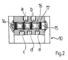
- Figure 2 shows a pneumatic reversing valve 10.
- the pilot pressures from Lines 9 are conducted into chambers 14,15 in both ends of stem 16.
- the stem glides in a cylinder formed inside the valve and opens and closes channels a - e in order to change the coupling.
- the stem has washers 17 gliding in the cylinder and thus being slightly stressed and long-lived.
- Working pressure is fed from gate d in turns to gates a or b, from there pressure lines continue to cylinder 1. Lines, which can also be connected with each other, start from gates c and e to choker 11.
- the control system will work even by sudden drop of working pressure, the oscillation starts moving always when there is enough working pressure to move the scraper, for instance.
- the adjustment of choker 11 alone is sufficient with no effect on the other functions.
- the piston turns in both ends on an air cushion without any mechanical contacts.
- the equipment can be a compact properly encased construction for severe conditions, for instance connected to a paper machine, whereby it is possible to keep the box around the construction under overpressure by means of escaping air streams.
- FIG. 3 shows one construction of this kind, where the reference numbers correspond to the equivalent reference numbers of figure 1.
- Valves 10, valves 5, the extruding head of shaft 18 with adjusting discs 4 on it are inside the box construction 20,21.
- one valve 5 is shown on shaft 18 front side and the other valve 5 behind the said valve.
- Pressure discharge is substantially continuous, since all the time the air stream is discharged from choke valve 11 to the box and further in turns from valves 5 when the piston is in the reversing points.
Landscapes
- Engineering & Computer Science (AREA)
- Physics & Mathematics (AREA)
- Fluid Mechanics (AREA)
- Mechanical Engineering (AREA)
- General Engineering & Computer Science (AREA)
- Actuator (AREA)
- Fluid-Pressure Circuits (AREA)
Claims (5)
- Steuerungssystem eines pneumatischen Schwingzylinders (1) um die Schwingbewegung eines, besonders in Papiermaschinen gebrauchten Abstreifers (3) zu produzieren, und um die Länge und Geschwindigkeit der erwähnten Bewegung zu regulieren, wobei es in der Kolbenstange (18) des Schwingzylinders Bewegungssperren (4) gibt, die zu ihrer Lage hinsichtlich des Kolbens regulierbar sind und in gewünschten Umkehrstellen der beiden Enden der Kolbenstange (18) für die erwähnte Sperre im Vorsteuerungskreis (9) eines pneumatischen Umkehrventils (10) das entsprechende Druckentlastungsventil (5) öffnen, wobei das Öffnen der beiden Druckbelastungsventile der Reihe nach eine Umkehrfunktion in dem pneumatischen Umkehrventil (10) herbeiführt, das den Arbeitsdruck zum Schwingzylinder (1) steuert, wobei sich die Kolbenstange (18) des Zylinders (1) symmetrisch durch den Zylinder streckt, und zwar um eine symmetrische Hin- und Herbewegung zu produzieren, und wobei die erwähnten Ventile und Sperren in einer eingekapselten Konstruktion (20,21) sind, indem der Kasten (20,21) unter Überdruck wenigstens mit Luftströmungen aus den Druckentlastungsventilen (5) gehalten wird.
- Ein Steuerungssystem gemäss Patentanspruch 1, wobei Luftströmungen aus Schwingzylinder (1) zu der Kastenkonstruktion (20,21) gesteuert werden, um Überdruck aufrecht zu erhalten.
- Ein Steuerungssystem gemäss Patentanspruch 1 oder 2, wobei es zur Regulieren der Bewegungsgeschwindigkeit in dem Kanal aus dem Zylinder (1) ein regulierbares Drosselventil (11) gibt, durch dem die Luftströmung zum Kasten (20,21) entlastet wird.
- Ein Steuerungssystem gemäss einem der obigen Patentansprüchen 1 - 3, wobei der Arbeitsdruck durch Drosselventil (8) zum Vorsteuerungskreis (9) des Umkehrventils (10) gesteuert wird, um eine genügende Drucksenkung im Vorsteuerungskreis (9) zu produzieren, wenn das Entlastungsventil (5) von der Sperre (4) geöffnet wird.
- Ein Steuerungssystem gemäss einem der obigen Patentansprüchen 1 - 3, wobei die Druckentlastung aus Ventilen (5,11) zum erwähnten Kasten im wesentlichen kontinuerlich ist.
Applications Claiming Priority (1)
| Application Number | Priority Date | Filing Date | Title |
|---|---|---|---|
| PCT/FI1997/000204 WO1998044264A1 (en) | 1995-10-04 | 1997-04-03 | Control system for an oscillation cylinder |
Publications (2)
| Publication Number | Publication Date |
|---|---|
| EP0972137A1 EP0972137A1 (de) | 2000-01-19 |
| EP0972137B1 true EP0972137B1 (de) | 2003-07-02 |
Family
ID=8556678
Family Applications (1)
| Application Number | Title | Priority Date | Filing Date |
|---|---|---|---|
| EP97915496A Expired - Lifetime EP0972137B1 (de) | 1997-04-03 | 1997-04-03 | Steuerungssystem für einen hin und her gehenden zylinder |
Country Status (5)
| Country | Link |
|---|---|
| US (1) | US6272968B1 (de) |
| EP (1) | EP0972137B1 (de) |
| CA (1) | CA2285617C (de) |
| DE (1) | DE69723313T2 (de) |
| WO (1) | WO1998044264A1 (de) |
Families Citing this family (11)
| Publication number | Priority date | Publication date | Assignee | Title |
|---|---|---|---|---|
| US6662704B2 (en) * | 2001-12-12 | 2003-12-16 | Internal Command International | Apparatus and method for generating power from a flowing liquid |
| FI20041503L (fi) * | 2004-11-23 | 2006-08-23 | Polarteknik Pmc Oy Ab | Järjestely oskillointisylinterin yhteydessä |
| FI118234B (fi) * | 2005-05-20 | 2007-08-31 | Metso Paper Inc | Toimilaite lineaariliikkeen aikaansaamiseksi |
| FI119197B (fi) * | 2006-11-13 | 2008-08-29 | Polarteknik Pmc Oy Ab | Oskillointisylinterin ohjaukseen tarkoitettu väline |
| CA2717385A1 (en) * | 2007-03-01 | 2008-09-04 | Luis Olvera Diaz | Improvements to the operation of a pressure generator |
| RU2455536C1 (ru) * | 2011-03-02 | 2012-07-10 | Валерий Владимирович Бодров | Автоколебательный гидравлический привод |
| CN104358721B (zh) * | 2014-10-27 | 2016-05-18 | 西安航空动力股份有限公司 | 一种流量试验用的气动换向装置 |
| JP6503566B2 (ja) * | 2015-04-01 | 2019-04-24 | イーグル工業株式会社 | アクチュエータ及び回転駆動装置 |
| AT16161U1 (de) * | 2016-07-21 | 2019-03-15 | Pimatic Oy | Oszillationsaktuator |
| DE102019113640B3 (de) * | 2019-05-22 | 2020-09-17 | Heraeus Medical Gmbh | Differenzdruckmotor und Verfahren zum Betreiben eines Differenzdruckmotors |
| CN119554282B (zh) * | 2025-02-07 | 2025-04-18 | 上海欣源液压设备成套有限公司 | 一种微型摆动油缸 |
Family Cites Families (6)
| Publication number | Priority date | Publication date | Assignee | Title |
|---|---|---|---|---|
| US2884860A (en) * | 1956-11-23 | 1959-05-05 | Black Sivalls & Bryson Inc | Apparatus for circulating a liquid in a fluid pressure system |
| DE1450878B2 (de) | 1964-11-17 | 1972-02-24 | VEB Kombinat Orsta Hydraulik Betrieb Industriewerke Karl Marx Stadt, χ 9030 Karl Marx Stadt | Hydrostatisches getriebe |
| DE1500537A1 (de) | 1965-05-17 | 1969-06-04 | Fritz Wegerdt | Anordnung zum Verzoegern und Beschleunigen von hydraulischen Getrieben mit ueber Null umsteuerbarer Druckmittelpumpe |
| AT278474B (de) | 1968-02-13 | 1970-02-10 | Fritz Wegerdt | Hydraulisches Getriebe für lineare Wechselbewegungen hoher Frequenz |
| DE1924177B2 (de) | 1969-05-12 | 1973-11-15 | Neumuenstersche Maschinen- Und Apparatebau Gmbh, 2350 Neumuenster | Zwirnmaschine mit hydraulisch ge steuerter Ringbank |
| US4680930A (en) * | 1983-12-05 | 1987-07-21 | Otis Engineering Corporation | Hydraulic control circuit and valve assembly |
-
1997
- 1997-04-03 CA CA002285617A patent/CA2285617C/en not_active Expired - Lifetime
- 1997-04-03 US US09/402,221 patent/US6272968B1/en not_active Expired - Lifetime
- 1997-04-03 EP EP97915496A patent/EP0972137B1/de not_active Expired - Lifetime
- 1997-04-03 DE DE69723313T patent/DE69723313T2/de not_active Expired - Lifetime
- 1997-04-03 WO PCT/FI1997/000204 patent/WO1998044264A1/en not_active Ceased
Also Published As
| Publication number | Publication date |
|---|---|
| WO1998044264A1 (en) | 1998-10-08 |
| US6272968B1 (en) | 2001-08-14 |
| CA2285617C (en) | 2007-01-09 |
| EP0972137A1 (de) | 2000-01-19 |
| CA2285617A1 (en) | 1998-10-08 |
| DE69723313T2 (de) | 2004-04-22 |
| DE69723313D1 (de) | 2003-08-07 |
Similar Documents
| Publication | Publication Date | Title |
|---|---|---|
| EP0972137B1 (de) | Steuerungssystem für einen hin und her gehenden zylinder | |
| US5385218A (en) | Rack and pinion pneumatic actuator with counter-pressure control and damping device | |
| EP1601500B1 (de) | Steuerventil für eine Stossvorrichtung, Verfahren für eine Stossvorrichtung und Stossvorrichtung | |
| US4379492A (en) | Torque control apparatus for pneumatic impact wrench | |
| DE59402372D1 (de) | Schwenktürantrieb | |
| US4321435A (en) | Fluid actuating device for an electric circuit breaker | |
| US4917001A (en) | Drive control valve for constant speed | |
| US20200248725A1 (en) | Oscillation cylinder arrangement | |
| CA2087700A1 (en) | Roll stop and operating method of the same | |
| EP1847720B1 (de) | Linearantriebsvorrichtung | |
| CA2221173C (en) | A method in a pneumatic oscillating device to observe an obstacle and to continue oscillating and corresponding oscillating device | |
| KR101230735B1 (ko) | 압력 유체 작동식 충격 장치를 제어하는 방법 및 충격 장치 | |
| WO1987004224A1 (en) | Actuating device for pipe-chamber feeders of hydraulic transport equipments | |
| US1116974A (en) | Oscillating engine and self-regulating gear therefor. | |
| CA2589254C (en) | Arrangement in connection with an oscillator cylinder | |
| CN1097177C (zh) | 流体压力驱动缸 | |
| US1085570A (en) | Unloading device. | |
| SU1732015A1 (ru) | Пневмопривод возвратно-поступательного действи с автоматическим реверсированием | |
| GB2268900A (en) | A process and a device for setting the insertion speed (welding arm movement speed) during welding using welding studs | |
| ITMI20060834A1 (it) | Apparecchiatura di posizionamento e bloccaggio,con copertura regolabile del braccio di lavoro. | |
| CA3089166A1 (en) | Control valve assembly for an indirect pneumatic control, and method for controlling a working fluid pressure | |
| SU1044831A1 (ru) | Дроссельное устройство напорной магистрали компрессора | |
| JPS6225585Y2 (de) | ||
| SU1155740A1 (ru) | Бурильна машина | |
| US939803A (en) | Pneumatic tool. |
Legal Events
| Date | Code | Title | Description |
|---|---|---|---|
| PUAI | Public reference made under article 153(3) epc to a published international application that has entered the european phase |
Free format text: ORIGINAL CODE: 0009012 |
|
| 17P | Request for examination filed |
Effective date: 19991029 |
|
| AK | Designated contracting states |
Kind code of ref document: A1 Designated state(s): DE FR GB IT SE |
|
| GRAH | Despatch of communication of intention to grant a patent |
Free format text: ORIGINAL CODE: EPIDOS IGRA |
|
| GRAH | Despatch of communication of intention to grant a patent |
Free format text: ORIGINAL CODE: EPIDOS IGRA |
|
| RAP1 | Party data changed (applicant data changed or rights of an application transferred) |
Owner name: POLARTEKNIK PMC OY AB |
|
| GRAA | (expected) grant |
Free format text: ORIGINAL CODE: 0009210 |
|
| AK | Designated contracting states |
Designated state(s): DE FR GB IT SE |
|
| REG | Reference to a national code |
Ref country code: GB Ref legal event code: FG4D |
|
| REF | Corresponds to: |
Ref document number: 69723313 Country of ref document: DE Date of ref document: 20030807 Kind code of ref document: P |
|
| ET | Fr: translation filed | ||
| REG | Reference to a national code |
Ref country code: SE Ref legal event code: TRGR |
|
| PLBE | No opposition filed within time limit |
Free format text: ORIGINAL CODE: 0009261 |
|
| STAA | Information on the status of an ep patent application or granted ep patent |
Free format text: STATUS: NO OPPOSITION FILED WITHIN TIME LIMIT |
|
| ET | Fr: translation filed | ||
| 26N | No opposition filed |
Effective date: 20040405 |
|
| PG25 | Lapsed in a contracting state [announced via postgrant information from national office to epo] |
Ref country code: IT Free format text: LAPSE BECAUSE OF NON-PAYMENT OF DUE FEES Effective date: 20080403 |
|
| PGRI | Patent reinstated in contracting state [announced from national office to epo] |
Ref country code: IT Effective date: 20110616 |
|
| PGFP | Annual fee paid to national office [announced via postgrant information from national office to epo] |
Ref country code: GB Payment date: 20110513 Year of fee payment: 15 |
|
| GBPC | Gb: european patent ceased through non-payment of renewal fee |
Effective date: 20120403 |
|
| PG25 | Lapsed in a contracting state [announced via postgrant information from national office to epo] |
Ref country code: GB Free format text: LAPSE BECAUSE OF NON-PAYMENT OF DUE FEES Effective date: 20120403 |
|
| REG | Reference to a national code |
Ref country code: FR Ref legal event code: PLFP Year of fee payment: 19 |
|
| REG | Reference to a national code |
Ref country code: FR Ref legal event code: PLFP Year of fee payment: 20 |
|
| PGFP | Annual fee paid to national office [announced via postgrant information from national office to epo] |
Ref country code: DE Payment date: 20160425 Year of fee payment: 20 |
|
| PGFP | Annual fee paid to national office [announced via postgrant information from national office to epo] |
Ref country code: FR Payment date: 20160426 Year of fee payment: 20 Ref country code: IT Payment date: 20160427 Year of fee payment: 20 Ref country code: SE Payment date: 20160421 Year of fee payment: 20 |
|
| REG | Reference to a national code |
Ref country code: DE Ref legal event code: R071 Ref document number: 69723313 Country of ref document: DE |