EP0972134B1 - Vorrichtung zur regelung des stromflusses durch einen verbraucher - Google Patents
Vorrichtung zur regelung des stromflusses durch einen verbraucher Download PDFInfo
- Publication number
- EP0972134B1 EP0972134B1 EP98925406A EP98925406A EP0972134B1 EP 0972134 B1 EP0972134 B1 EP 0972134B1 EP 98925406 A EP98925406 A EP 98925406A EP 98925406 A EP98925406 A EP 98925406A EP 0972134 B1 EP0972134 B1 EP 0972134B1
- Authority
- EP
- European Patent Office
- Prior art keywords
- voltage
- measuring
- line
- computing unit
- output line
- Prior art date
- Legal status (The legal status is an assumption and is not a legal conclusion. Google has not performed a legal analysis and makes no representation as to the accuracy of the status listed.)
- Expired - Lifetime
Links
- 230000001105 regulatory effect Effects 0.000 title claims description 5
- 230000005611 electricity Effects 0.000 title 1
- 230000001419 dependent effect Effects 0.000 claims description 4
- 230000005540 biological transmission Effects 0.000 description 4
- 238000002485 combustion reaction Methods 0.000 description 2
- 230000001276 controlling effect Effects 0.000 description 2
- 238000004891 communication Methods 0.000 description 1
- 238000000034 method Methods 0.000 description 1
- 239000000203 mixture Substances 0.000 description 1
- 238000012544 monitoring process Methods 0.000 description 1
- 238000002360 preparation method Methods 0.000 description 1
- 230000000630 rising effect Effects 0.000 description 1
- 230000008054 signal transmission Effects 0.000 description 1
Images

Classifications
-
- F—MECHANICAL ENGINEERING; LIGHTING; HEATING; WEAPONS; BLASTING
- F02—COMBUSTION ENGINES; HOT-GAS OR COMBUSTION-PRODUCT ENGINE PLANTS
- F02P—IGNITION, OTHER THAN COMPRESSION IGNITION, FOR INTERNAL-COMBUSTION ENGINES; TESTING OF IGNITION TIMING IN COMPRESSION-IGNITION ENGINES
- F02P3/00—Other installations
- F02P3/02—Other installations having inductive energy storage, e.g. arrangements of induction coils
- F02P3/04—Layout of circuits
- F02P3/05—Layout of circuits for control of the magnitude of the current in the ignition coil
-
- F—MECHANICAL ENGINEERING; LIGHTING; HEATING; WEAPONS; BLASTING
- F02—COMBUSTION ENGINES; HOT-GAS OR COMBUSTION-PRODUCT ENGINE PLANTS
- F02P—IGNITION, OTHER THAN COMPRESSION IGNITION, FOR INTERNAL-COMBUSTION ENGINES; TESTING OF IGNITION TIMING IN COMPRESSION-IGNITION ENGINES
- F02P3/00—Other installations
- F02P3/02—Other installations having inductive energy storage, e.g. arrangements of induction coils
- F02P3/04—Layout of circuits
- F02P3/05—Layout of circuits for control of the magnitude of the current in the ignition coil
- F02P3/051—Opening or closing the primary coil circuit with semiconductor devices
- F02P3/053—Opening or closing the primary coil circuit with semiconductor devices using digital techniques
Definitions
- the invention relates to a device for regulating the Current flow according to the preamble of claim 1 and 2.
- From DE 38 26 663 A1 discloses a method and a circuit for simultaneous transmission of operating data known in the Transfer operating data and voice signals over one line become.
- the peak values of the operating data increase chosen as the maximum peaks of the speech signals, so that the signals can be mixed and at the receiving site from the speech signal using a comparison voltage the operating data can be determined again.
- the Speech signal is obtained by subtracting the rejected operational data obtained from the signal mixture.
- a device for serial Data exchange between two stations via a common Data transmission line.
- the first station recognizes due different voltage levels the different ones Bit states on the data line.
- the second station detects due to the existence or non-existence a certain current flow the different bit states on the data transmission line.
- the voltage levels are evaluated differently by the stations, so that a simultaneous data transmission in both directions possible is.
- From DE 40 05 813 A1 is already a device for control the current flow through a consumer known in which the Consumer with a transistor and a measuring resistor in Row is switched.
- the at the measuring resistor by the load current caused voltage drop is using an operational amplifier compared with a reference voltage. Is the Voltage drop at the measuring resistor greater than a predetermined Value, an output signal is sent to the controller the load current is used.
- the object of the invention is based on a simply constructed Device for controlling the flow of current through a Provide consumers with an accurate and simple scheme the current flow is enabled.
- FIG. 1 shows an electronic circuit arrangement for regulating the flow of current through a primary coil 1, the one Consumer represents.
- the primary coil 1 is connected to an input connected via an input line 18 to a battery 17.
- Parallel to the primary coil 1 is a secondary coil. 2 connected to the battery 17, whose output via a Ignition 19 is guided to a spark plug 3, which in turn with its output connected to ground.
- the spark plug 3 is arranged in the combustion chamber of an internal combustion engine.
- the primary coil 1 is connected to the output via an output line 20 to the collector terminal C of a first transistor 4th connected.
- the emitter terminal E of the transistor 4 leads via a measuring line 21 to a first measuring resistor 5, the connected to ground.
- the measuring line 21 is the Input of a voltage-dependent current source 8 connected, whose output is connected to an output line 9.
- the measuring line 21 is also connected to a first input 22 of a Operational amplifier 6 connected.
- the second input 23 of Operational amplifier 6 is connected to a reference voltage source 24 connected, preferably a constant voltage emits.
- the output 26 of the operational amplifier 6 is connected to the Base terminal B of a second transistor 7 connected, its emitter terminal E to ground and its collector terminal C is in communication with an output line 9.
- the Output line 9 is connected via a second measuring resistor 16 a predetermined potential, in this case +5 V, connected.
- a predetermined potential in this case +5 V
- the arithmetic unit 10 has a Steuerausganq 13th on, via a control line 27 and a first resistor 14 is connected to the gate terminal G of the first transistor 4 is.
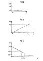
- the voltage on the measuring line changes 21 is applied, proportional, so that the voltage-dependent Current source 8 a second stream on the output line 9 outputs, which is proportional to the primary current, and with the time increases linearly.
- the operational amplifier 6 controls the second transistor 7 only when the primary current exceeds the limit current ICL at time TL. Consequently the voltage behaves at the analogue input 12 and at the digital input 11 as a function of the primary current IC accordingly the course shown in Figure 4.
- the arithmetic unit 10 regulates on the one hand via the transistor 4th the current flow through the primary coil 1. At the same time monitors the Arithmetic unit 10 with an analog input 12 and a digital input 11 the current flow through the primary coil 1. At the analog input 12, an analog-to-digital converter is provided which the voltage applied to the output line 9 in a voltage corresponding digital value, which then converts the arithmetic unit 10 used to control the transistor 4.
- the arithmetic unit 10 monitors the at the digital input 11 voltage applied. Is the voltage at the digital input 11 in the high range, that is over 2.4 volts, so regulates the Computing unit 10, the current flow through the primary coil 1 via the voltage values picked up by the analog input 12.
- the computing unit 10 detects that the digital input 11 a low signal is present, which is below 0.8 volts, so is from the arithmetic unit 10, preferably at a calculated ignition point, the first transistor 4 is driven in such a way that the Current flow through the primary coil 1 is interrupted and thus in the secondary coil 2, a high ignition voltage is generated, so that the spark plug 3 ignites.
- connection of an analog and a digital input 12, 11 with a single output line 9 has the advantage that on the output line 9 both an analog information as well as digital information can be transmitted.
- the analogue information is used for the regulation of the amperage, which flows through the primary coil 1 used and the digital Information is considered protection against overcurrent and as Sign used that the primary coil 1 sufficient is charged to perform ignition of the spark plug 3.
- the analog information in the form of a voltage change the output line 9 is to be chosen so that the value range for a high signal or the value range for a low signal not leave so that the analog information the digital Information not from a high signal to a low signal or vice versa changes.
- the monitoring of an overcurrent via a digital Input 11 advantageous because a scan of the digital Input 11 is performed faster and more often than at the analog input 12 and thus when too large Current that could damage the primary coil 1, quickly the primary current can be reduced.
- the computing unit 10 knows the voltage value that the digital Signal in high state and in low state occupies. In order to calculates the arithmetic unit from the voltage applied to the analog input 12 Voltage the value of the analog signal. In addition is the analog signal advantageously dimensioned such that in the overlap between the analog and the digital Signal the arithmetic unit 10 always the value of the digital Detects signal.
- the first transistor 4 provides a second switch and the second transistor 7 provides a first Switch.
Landscapes
- Engineering & Computer Science (AREA)
- Chemical & Material Sciences (AREA)
- Combustion & Propulsion (AREA)
- Mechanical Engineering (AREA)
- General Engineering & Computer Science (AREA)
- Measurement Of Current Or Voltage (AREA)
- Ignition Installations For Internal Combustion Engines (AREA)
- Continuous-Control Power Sources That Use Transistors (AREA)
Description
- Figur 1
- eine Vorrichtung zum Regeln des Stromflusses,
- Figur 2
- einen Spannungsverlauf auf der Meßleitung,
- Figur 3
- einen Stromverlauf auf der Meßleitung und
- Figur 4
- die Spannung VM auf der Ausgangsleitung in Abhängigkeit vom Stromfluß IC auf der Meßleitung.
Claims (5)
- Vorrichtung zum Regeln des Stromflusses durch einen Verbraucher (1), der über eine Meßleitung (21) mit Masse verbunden ist,dadurch gekennzeichnet, daßmit Mitteln, die mit der Meßleitung (21) verbunden sind, und die in Abhängigkeit von der auf der Meßleitung (21) vorliegenden Meßspannung einen ersten Strom auf eine Ausgangsleitung (9) ausgeben,eine Recheneinheit (10) vorgesehen ist, die über einen Analogeingang (12) und über einen Digitaleingang (11) mit der Ausgangsleitung (9) verbunden ist,daß die Recheneinheit (10) über den Analogeingang den Wert der Spannung auf der Ausgangsleitung erfaßt, daß die Recheneinheit in Abhängigkeit von der über den Analogeingang ermittelten Spannung über einen ersten Schalter (4) den Stromfluß durch den Verbraucher regelt,daß die Recheneinheit (10) über den Digitaleingang die Spannung auf der Ausgangsleitung dahingehend erfaßt, ob ein Low-Signal anliegt, unddaß die Recheneinheit bei einem Low-Signal auf dem Digitaleingang den ersten Schalter (4) in einem vorgebbaren Zeitbereich öffnet und dadurch den Stromfluß durch den Verbraucher (1) unterbricht.
- Vorrichtung zum Regeln des Stromflusses durch einen Verbraucher (1), der zwischen einem positiven Potential (17) und einem ersten Meßwiderstand (5) geschaltet ist, der über eine Meßleitung (21) mit Masse verbunden ist,mit ersten Mitteln, die mit der Meßleitung (21) verbunden sind und in Abhängigkeit von der auf der Meßleitung (21) vorliegenden Meßspannung einen ersten Strom auf eine Ausgangsleitung (9) ausgeben, die über einen zweiten Meßwiderstand (16) mit einem vorgegebenen Potential verbunden ist,dadurch gekennzeichnet, daß zweite Mittel vorgesehen sind, die mit der Meßleitung (21) verbunden sind, und die einen zweiten von der Meßspannung abhängigen Strom auf die Ausgangsleitung (9) geben, wenn die Meßspannung kleiner als ein vorgegebener Grenzwert ist, wobei der zweite Stromfluß so groß ist, daß die Spannung auf der Ausgangsleitung (9) unter einen vorgegebenen Wert fällt, miteiner Recheneinheit (10), die über einen Analogeingang (12) und über einen Digitaleingang (11) mit der Ausgangsleitung (9) verbunden ist,daß die Recheneinheit (10) über eine Steuerleitung (27) mit einem ersten Schalter (4) verbunden ist, der zwischen den Verbraucher (1) und die Meßleitung eingebracht ist,daß die Recheneinheit (10) über den Analogeingang den Wert der Spannung auf der Ausgangsleitung erfaßt, daß die Recheneinheit in Abhängigkeit von der über den Analogeingang ermittelten Spannung den ersten Schalter (4) steuert und dadurch den Stromfluß durch den Verbraucher regelt,daß die Recheneinheit (10) über den Digitaleingang die Spannung auf der Ausgangsleitung dahingehend erfaßt, ob ein Low-Signal anliegt, unddaß die Recheneinheit bei einem Low-Signal auf dem Digital-eingang den ersten Schalter (4) in einem vorgebbaren Zeitbereich öffnet und dadurch den Stromfluß durch den Verbraucher (1) unterbricht.
- Vorrichtung nach Anspruch 1 und 2, dadurch gekennzeichnet, daß als erste Mittel eine spannungsabhängige Stromquelle (8) verwendet wird.
- Vorrichtung nach Anspruch 2, dadurch gekennzeichnet, daß als zweite Mittel ein Operationsverstärker (6) vorgesehen ist, der mit einem ersten Eingang mit der Meßleitung (21) und mit einem zweiten Eingang mit einer konstanten Spannungsquelle (24) verbunden ist, und der mit einem Ausgang an einen zweiten Schalter (7) geführt ist, über den die Ausgangsleitung (9) mit Masse verbindbar ist, wobei der Operationsverstärker die Meßspannung mit der Referenzspannung der Spannungsquelle (24) vergleicht und den zweiten Schalter (7) öffnet, wenn die Meßspannung kleiner als die Referenzspannung ist und den zweiten Schalter (7) schließt, wenn die Meßspannung größer als die Referenzspannung ist.
- Vorrichtung nach einem der Ansprüche 1 - 4, dadurch gekennzeichnet, daß als Verbraucher (1) eine Zündspule angeordnet ist, die von der Recheneinheit (10) gegen Überstrom geschützt wird.
Applications Claiming Priority (3)
| Application Number | Priority Date | Filing Date | Title |
|---|---|---|---|
| DE19713981A DE19713981A1 (de) | 1997-04-04 | 1997-04-04 | Vorrichtung zum Zuführen eines analogen und eines digitalen Signals zu einer Recheneinheit und Vorrichtung zur Regelung des Stromflusses durch einen Verbraucher |
| DE19713981 | 1997-04-04 | ||
| PCT/DE1998/000799 WO1998045597A1 (de) | 1997-04-04 | 1998-03-18 | Vorrichtung zur regelung des stromflusses durch einen verbraucher |
Publications (2)
| Publication Number | Publication Date |
|---|---|
| EP0972134A1 EP0972134A1 (de) | 2000-01-19 |
| EP0972134B1 true EP0972134B1 (de) | 2005-10-26 |
Family
ID=7825472
Family Applications (1)
| Application Number | Title | Priority Date | Filing Date |
|---|---|---|---|
| EP98925406A Expired - Lifetime EP0972134B1 (de) | 1997-04-04 | 1998-03-18 | Vorrichtung zur regelung des stromflusses durch einen verbraucher |
Country Status (6)
| Country | Link |
|---|---|
| US (1) | US6204693B1 (de) |
| EP (1) | EP0972134B1 (de) |
| JP (1) | JP2001521655A (de) |
| KR (1) | KR100564086B1 (de) |
| DE (2) | DE19713981A1 (de) |
| WO (1) | WO1998045597A1 (de) |
Families Citing this family (8)
| Publication number | Priority date | Publication date | Assignee | Title |
|---|---|---|---|---|
| DE10230216A1 (de) * | 2002-07-04 | 2004-01-22 | Endress + Hauser Gmbh + Co. Kg | Verfahren zur funktional sicheren Datenübertragung zwischen einem Sensor und einer Auswerteeinheit |
| JP3607902B2 (ja) * | 2002-07-22 | 2005-01-05 | 三菱電機株式会社 | 内燃機関用点火装置 |
| FR2853941B1 (fr) * | 2003-04-17 | 2007-02-09 | Siemens Vdo Automotive | Procede de controle du courant primaire d'allumage d'un moteur a combustion interne a allumage commande |
| US7002326B1 (en) * | 2003-09-08 | 2006-02-21 | National Semiconductor Corporation | Method of modulating current regulation control loop's current magnitude from a second control signal |
| DE102004025909A1 (de) * | 2004-05-27 | 2005-12-22 | Infineon Technologies Ag | Stromversorgungsanordnung zur Stromversorgung einer Last |
| JP4746942B2 (ja) * | 2005-08-31 | 2011-08-10 | 三洋電機株式会社 | モータ速度制御集積回路 |
| CN106438155A (zh) * | 2016-09-28 | 2017-02-22 | 中国第汽车股份有限公司 | 具有点火能量自适应调节功能的点火系统及控制方法 |
| CN108204325B (zh) * | 2018-03-03 | 2024-03-15 | 东莞传动电喷科技有限公司 | 一种一体化点火线圈 |
Family Cites Families (12)
| Publication number | Priority date | Publication date | Assignee | Title |
|---|---|---|---|---|
| IT1208855B (it) * | 1987-03-02 | 1989-07-10 | Marelli Autronica | Sistema di accensione ad energia di scintilla variabile per motori acombustione interna particolarmente per autoveicoli |
| DE3826663A1 (de) * | 1988-08-05 | 1990-02-08 | Eickhoff Geb | Verfahren und schaltung zum gleichzeitigen uebertragen von betriebsdaten und/oder steuerbefehlen einer untertage eingesetzten bergwerksmaschine und von sprachsignalen des maschinenbegleiters |
| DE3908558A1 (de) * | 1989-03-16 | 1990-09-20 | Knick Elekt Messgeraete Gmbh | Signaluebertragungssystem |
| US5043633A (en) * | 1989-11-13 | 1991-08-27 | Ncr Corporation | Circuit and method for regulating the current flow in a distributorless ignition system coil |
| DE4005813C2 (de) * | 1990-02-23 | 2002-01-10 | Siemens Ag | Vorrichtung zur Überwachung des Laststromes eines elektronisch geschalteten Verbrauchers |
| JPH0579436A (ja) * | 1991-09-17 | 1993-03-30 | Nippondenso Co Ltd | 内燃機関の点火装置 |
| DE4231954C2 (de) * | 1992-09-24 | 1994-10-20 | Telefunken Microelectron | Zündenergiesteuerung für Brennkraftmaschinen |
| JPH0828415A (ja) * | 1994-07-14 | 1996-01-30 | Hitachi Ltd | 内燃機関用点火装置 |
| DE19511140B4 (de) * | 1995-03-27 | 2007-08-09 | Robert Bosch Gmbh | Vorrichtung zum seriellen Datenaustausch zwischen zwei Stationen |
| US6100728A (en) * | 1995-07-31 | 2000-08-08 | Delco Electronics Corp. | Coil current limiting feature for an ignition coil driver module |
| EP0780570B1 (de) * | 1995-12-18 | 2002-08-14 | Fuji Electric Co., Ltd. | Halbleiterzündschaltungsvorrichtung mit Strombegrenzung für eine Brennkraftmaschine |
| US5775310A (en) * | 1996-12-24 | 1998-07-07 | Hitachi, Ltd. | Ignition device for an internal combustion engine |
-
1997
- 1997-04-04 DE DE19713981A patent/DE19713981A1/de not_active Withdrawn
-
1998
- 1998-03-18 WO PCT/DE1998/000799 patent/WO1998045597A1/de not_active Ceased
- 1998-03-18 KR KR1019997009117A patent/KR100564086B1/ko not_active Expired - Fee Related
- 1998-03-18 DE DE59813143T patent/DE59813143D1/de not_active Expired - Fee Related
- 1998-03-18 EP EP98925406A patent/EP0972134B1/de not_active Expired - Lifetime
- 1998-03-18 JP JP54222298A patent/JP2001521655A/ja not_active Ceased
-
1999
- 1999-10-04 US US09/412,063 patent/US6204693B1/en not_active Expired - Fee Related
Also Published As
| Publication number | Publication date |
|---|---|
| DE19713981A1 (de) | 1998-10-15 |
| WO1998045597A1 (de) | 1998-10-15 |
| KR20010006039A (ko) | 2001-01-15 |
| JP2001521655A (ja) | 2001-11-06 |
| DE59813143D1 (de) | 2005-12-01 |
| KR100564086B1 (ko) | 2006-03-27 |
| US6204693B1 (en) | 2001-03-20 |
| EP0972134A1 (de) | 2000-01-19 |
Similar Documents
| Publication | Publication Date | Title |
|---|---|---|
| DE4005609B4 (de) | Verfahren und Vorrichtung zur Funktionsüberwachung eines elektrischen Verbrauchers | |
| EP0393233B1 (de) | Signalübertragungssystem | |
| EP0543826B1 (de) | Verfahren und einrichtung zur ansteuerung eines elektromagnetischen verbrauchers | |
| DE19710073A1 (de) | Vorrichtung und Verfahren zum Überspannungsschutz | |
| DE2644643A1 (de) | Spannungsregler fuer generatoren in kraftfahrzeugen | |
| DE68928176T2 (de) | Leistungshalbleitervorrichtung | |
| DE102004062032A1 (de) | Schaltungsanordnung zur schnellen Reduzierung eines induzierten Stroms | |
| WO1998045597A1 (de) | Vorrichtung zur regelung des stromflusses durch einen verbraucher | |
| DE19652267A1 (de) | Induktives Spulenzündsystem für einen Motor | |
| DE2829828A1 (de) | Zuendanlage fuer eine brennkraftmaschine | |
| DE69524139T2 (de) | Selektives Stromversorgungsgerät für elektrische Verbraucher und Zündsystem von inneren Brennkraftmaschinen in Motorfahrzeugen | |
| EP0698794A1 (de) | Schaltungsanordnung zur Unterspannungs-Erkennung | |
| EP0207086A1 (de) | Schaltungsanordnung zur überwachung der stromversorgung eines elektrischen verbrauchers. | |
| EP0671088A1 (de) | Schaltungsanordnung zum steuern einer mehrzahl von verbrauchern, insbesondere vorschaltgeräten von lampen. | |
| DE3209070C2 (de) | Schaltungsanordnung zum Schalten elektrischer Lasten | |
| WO2015062837A1 (de) | Schnittstelle mit verbessertem sendezweig | |
| EP0852895B1 (de) | Getaktete stromversorgungsschaltung mit einer von einem verbraucher unabhängigen, zumindest zeitweise wirksamen last | |
| DE4330114B4 (de) | Schaltungsanordnung zum Steuern einer Mehrzahl von Verbrauchern, insbesondere Vorschaltgerät von Lampen | |
| EP0164511B1 (de) | Überwachungsschaltung zur Auswertung der Über- bzw. Unterschreitung vorgegebener Grenzwerte | |
| EP0014328B1 (de) | Belegschaltung an einer "ankommenden" c-Ader in einer Fernmeldeeinrichtung | |
| DE112018008224T5 (de) | Ionenstrom-Detektionsschaltung, Zündsteuerungsgerät und Zündsystem | |
| DE68918234T2 (de) | Zündanlage mit induktive Ausladung bei Brennkraftmaschinen. | |
| DE3013474A1 (de) | Sensorsystem | |
| DE3248355A1 (de) | Schaltungsanordnung zur abgabe von waehlimpulsen in einer fernmelde-, insbesondere fernsprechanlage | |
| DE69534510T2 (de) | Ansteuereinrichtung eines Hochstromschalters mit isoliertem Gate und Impulsschalter unter Verwendung derselben |
Legal Events
| Date | Code | Title | Description |
|---|---|---|---|
| PUAI | Public reference made under article 153(3) epc to a published international application that has entered the european phase |
Free format text: ORIGINAL CODE: 0009012 |
|
| 17P | Request for examination filed |
Effective date: 19990917 |
|
| AK | Designated contracting states |
Kind code of ref document: A1 Designated state(s): DE FR GB IT |
|
| 17Q | First examination report despatched |
Effective date: 20040525 |
|
| GRAP | Despatch of communication of intention to grant a patent |
Free format text: ORIGINAL CODE: EPIDOSNIGR1 |
|
| GRAS | Grant fee paid |
Free format text: ORIGINAL CODE: EPIDOSNIGR3 |
|
| GRAA | (expected) grant |
Free format text: ORIGINAL CODE: 0009210 |
|
| AK | Designated contracting states |
Kind code of ref document: B1 Designated state(s): DE FR GB IT |
|
| PG25 | Lapsed in a contracting state [announced via postgrant information from national office to epo] |
Ref country code: IT Free format text: LAPSE BECAUSE OF FAILURE TO SUBMIT A TRANSLATION OF THE DESCRIPTION OR TO PAY THE FEE WITHIN THE PRESCRIBED TIME-LIMIT;WARNING: LAPSES OF ITALIAN PATENTS WITH EFFECTIVE DATE BEFORE 2007 MAY HAVE OCCURRED AT ANY TIME BEFORE 2007. THE CORRECT EFFECTIVE DATE MAY BE DIFFERENT FROM THE ONE RECORDED. Effective date: 20051026 Ref country code: GB Free format text: LAPSE BECAUSE OF FAILURE TO SUBMIT A TRANSLATION OF THE DESCRIPTION OR TO PAY THE FEE WITHIN THE PRESCRIBED TIME-LIMIT Effective date: 20051026 |
|
| REG | Reference to a national code |
Ref country code: GB Ref legal event code: FG4D Free format text: NOT ENGLISH |
|
| REF | Corresponds to: |
Ref document number: 59813143 Country of ref document: DE Date of ref document: 20051201 Kind code of ref document: P |
|
| GBV | Gb: ep patent (uk) treated as always having been void in accordance with gb section 77(7)/1977 [no translation filed] |
Effective date: 20051026 |
|
| ET | Fr: translation filed | ||
| PLBE | No opposition filed within time limit |
Free format text: ORIGINAL CODE: 0009261 |
|
| STAA | Information on the status of an ep patent application or granted ep patent |
Free format text: STATUS: NO OPPOSITION FILED WITHIN TIME LIMIT |
|
| 26N | No opposition filed |
Effective date: 20060727 |
|
| PGFP | Annual fee paid to national office [announced via postgrant information from national office to epo] |
Ref country code: DE Payment date: 20090320 Year of fee payment: 12 |
|
| PGFP | Annual fee paid to national office [announced via postgrant information from national office to epo] |
Ref country code: FR Payment date: 20090312 Year of fee payment: 12 |
|
| REG | Reference to a national code |
Ref country code: FR Ref legal event code: ST Effective date: 20101130 |
|
| PG25 | Lapsed in a contracting state [announced via postgrant information from national office to epo] |
Ref country code: FR Free format text: LAPSE BECAUSE OF NON-PAYMENT OF DUE FEES Effective date: 20100331 |
|
| PG25 | Lapsed in a contracting state [announced via postgrant information from national office to epo] |
Ref country code: DE Free format text: LAPSE BECAUSE OF NON-PAYMENT OF DUE FEES Effective date: 20101001 |