EP0971544A2 - Vorrichtung und Verfahren zur Bildkodierung für lokalisierte Dekodierung in mehreren Auflösungen - Google Patents
Vorrichtung und Verfahren zur Bildkodierung für lokalisierte Dekodierung in mehreren Auflösungen Download PDFInfo
- Publication number
- EP0971544A2 EP0971544A2 EP99304937A EP99304937A EP0971544A2 EP 0971544 A2 EP0971544 A2 EP 0971544A2 EP 99304937 A EP99304937 A EP 99304937A EP 99304937 A EP99304937 A EP 99304937A EP 0971544 A2 EP0971544 A2 EP 0971544A2
- Authority
- EP
- European Patent Office
- Prior art keywords
- image
- tile
- subband
- tiles
- level
- Prior art date
- Legal status (The legal status is an assumption and is not a legal conclusion. Google has not performed a legal analysis and makes no representation as to the accuracy of the status listed.)
- Granted
Links
Images


Classifications
-
- H—ELECTRICITY
- H04—ELECTRIC COMMUNICATION TECHNIQUE
- H04N—PICTORIAL COMMUNICATION, e.g. TELEVISION
- H04N19/00—Methods or arrangements for coding, decoding, compressing or decompressing digital video signals
- H04N19/30—Methods or arrangements for coding, decoding, compressing or decompressing digital video signals using hierarchical techniques, e.g. scalability
- H04N19/36—Scalability techniques involving formatting the layers as a function of picture distortion after decoding, e.g. signal-to-noise [SNR] scalability
-
- H—ELECTRICITY
- H04—ELECTRIC COMMUNICATION TECHNIQUE
- H04N—PICTORIAL COMMUNICATION, e.g. TELEVISION
- H04N19/00—Methods or arrangements for coding, decoding, compressing or decompressing digital video signals
- H04N19/10—Methods or arrangements for coding, decoding, compressing or decompressing digital video signals using adaptive coding
- H04N19/134—Methods or arrangements for coding, decoding, compressing or decompressing digital video signals using adaptive coding characterised by the element, parameter or criterion affecting or controlling the adaptive coding
- H04N19/162—User input
-
- H—ELECTRICITY
- H04—ELECTRIC COMMUNICATION TECHNIQUE
- H04N—PICTORIAL COMMUNICATION, e.g. TELEVISION
- H04N19/00—Methods or arrangements for coding, decoding, compressing or decompressing digital video signals
- H04N19/10—Methods or arrangements for coding, decoding, compressing or decompressing digital video signals using adaptive coding
- H04N19/169—Methods or arrangements for coding, decoding, compressing or decompressing digital video signals using adaptive coding characterised by the coding unit, i.e. the structural portion or semantic portion of the video signal being the object or the subject of the adaptive coding
- H04N19/17—Methods or arrangements for coding, decoding, compressing or decompressing digital video signals using adaptive coding characterised by the coding unit, i.e. the structural portion or semantic portion of the video signal being the object or the subject of the adaptive coding the unit being an image region, e.g. an object
-
- H—ELECTRICITY
- H04—ELECTRIC COMMUNICATION TECHNIQUE
- H04N—PICTORIAL COMMUNICATION, e.g. TELEVISION
- H04N19/00—Methods or arrangements for coding, decoding, compressing or decompressing digital video signals
- H04N19/60—Methods or arrangements for coding, decoding, compressing or decompressing digital video signals using transform coding
- H04N19/63—Methods or arrangements for coding, decoding, compressing or decompressing digital video signals using transform coding using sub-band based transform, e.g. wavelets
- H04N19/64—Methods or arrangements for coding, decoding, compressing or decompressing digital video signals using transform coding using sub-band based transform, e.g. wavelets characterised by ordering of coefficients or of bits for transmission
- H04N19/645—Methods or arrangements for coding, decoding, compressing or decompressing digital video signals using transform coding using sub-band based transform, e.g. wavelets characterised by ordering of coefficients or of bits for transmission by grouping of coefficients into blocks after the transform
-
- H—ELECTRICITY
- H04—ELECTRIC COMMUNICATION TECHNIQUE
- H04N—PICTORIAL COMMUNICATION, e.g. TELEVISION
- H04N19/00—Methods or arrangements for coding, decoding, compressing or decompressing digital video signals
- H04N19/10—Methods or arrangements for coding, decoding, compressing or decompressing digital video signals using adaptive coding
- H04N19/102—Methods or arrangements for coding, decoding, compressing or decompressing digital video signals using adaptive coding characterised by the element, parameter or selection affected or controlled by the adaptive coding
- H04N19/124—Quantisation
Definitions
- the present invention relates to a method and apparatus for digital image compression and in particular to an encoding method which allows efficient decoding of a localised portion of a digital image.
- the JPEG compression standard is widely used for image compression. It offers good rate-distortion (compression) performance. In the baseline mode efficient random access is possible. However, variable resolution decoding is not particularly efficient, since the information for each (8x8) image blocks is stored contiguously in the compressed image bit stream. For example, to read just the DC coefficients from baseline mode coded JPEG image to decode a very low resolution version of the image from a disk is typically as costly (if possibly not more costly) as reading the whole JPEG image from the disk, since the DC coefficients are interspersed all along the bit stream.
- a hierarchal JPEG mode offers efficient decoding of different resolutions (or image sizes) but does not allow such an efficient random access. Further the hierarchical JPEG format itself is redundant. That is, a hierarchal JPEG mode typically gives a 33% larger compressed file than the other modes, since the different image resolutions are stored somewhat independently.
- these subband schemes do not offer efficient random access.
- the problem with these schemes are that the subbands are interspersed in a bit stream and to decode a portion of the image requires searching the bit stream for coefficients relating to the desired portion of the image to be decoded. This is quite inefficient particularly where the information (coefficients) is read from memory storage devices having relatively long access times.
- Such devices include CD ROM drives, floppy disk drives, hard disk drives and alike.
- Reading data from storage media such as hard disks and CD ROM drives is often a relatively time consuming operation. In particular it takes a relatively long time to do a seek operation: that is to find the start of any given data segment on the storage media. For this reason when reading data a minimum data chunk is typically read. Thus reading small data segments regularly situated in a large bit stream can be as time consuming as reading the whole bit stream.
- a method of encoding a coded representation of a digital image wherein the coded representation includes a non-redundant hierarchical code, having one low frequency subband and a plurality of high frequency subbands arranged in levels, which levels combine to represent multiple resolutions of the image, said method including the steps of: a) dividing each subband into a plurality of tiles; b) entropy encoding each tile; c) selecting a plurality of desired resolutions from said multiple resolutions; and d) arranging in contiguous manner, for each level between each pair of adjacent selected resolutions, each entropy encoded tile representing substantially the same portion of image into a bit stream.
- a method of encoding a digital image to provide substantially random access to portions of said image at a plurality of nominated resolutions, said method including the steps of: applying a linear transform to said image to produce a plurality of transform coefficients in a frequency domain; grouping the transform coefficients into frequency subbands, each subband representing a range of frequencies of the image, wherein said grouping is characterised by one low frequency subband and a plurality of high frequency subbands arranged in levels, and wherein each level represents frequency contributions between adjacent nominated resolutions of the image; dividing each frequency subband into a plurality of tiles, each tile comprising at least one of said transform coefficient; quantising and entropy coding each said tile; and arranging in a contiguous manner, for each level, those encoded tiles which substantially correspond to the same portions of the image into a bit stream.
- a method of encoding a digital image into a bit stream to provide substantially random access to portions of said image at a plurality of nominated resolutions, said method including the steps of: applying a discrete wavelet transform to said image to produce a non-redundant multiple resolution frequency domain representation of the image, said representation comprising one low frequency subband and a plurality of high frequency subbands arranged in levels, wherein each level represents frequency contributions between adjacent resolutions of the image; dividing each frequency subband into a plurality of tiles; quantising and entropy coding each said tile; nominating desired resolutions of the digital image; and arranging in a contiguous manner, for each level between nominated resolutions, those tiles which substantially correspond to the same portions of the image into the bit stream.
- a method of encoding a digital image including the steps of: applying a linear transform to said image to produce a non-redundant multiple resolution frequency domain representation of the image said representation comprising a plurality of levels, wherein each level represents frequency contributions between adjacent resolutions of the image: dividing said non-redundant multiple resolution frequency domain representation into a plurality of tiles; quantising and entropy coding each said tile: nominating desired resolutions of the digital image; and arranging contiguous manner, for each level between nominated resolutions, those tiles which substantially correspond to the same portions of the image.
- a method of encoding a coded representation of a digital image wherein the coded representation includes a non-redundant hierarchical code, having one low frequency subband and a plurality of high frequency subbands arranged in levels, which levels combine to represent multiple resolutions of the image, said method including the steps of: a) dividing each subband into a plurality of tiles; b) selecting a predetermined number of said levels from said multiple resolutions; c) entropy encoding each tile; d) processing said selected levels in a predetermined sequential order; and e) arranging in contiguous manner, for each level in said sequence to a current level not processed in step d), each entropy encoded tile representing substantially the same portion of image into a bit stream.
- a method of encoding a digital image into a bit stream including the steps of: applying a discrete wavelet transform to said image to produce a non-redundant multiple resolution frequency domain representation of the image, said representation comprising one low frequency subband and a plurality of high frequency subbands arranged in levels, wherein each level represents frequency contributions between adjacent resolutions of the image; dividing each frequency subband into a plurality of tiles; quantising and entropy coding each said tile; arranging into said bit stream in a predetermined order each said entropy tile of DC subband; and arranging in a contiguous manner each set of three encoded tiles belonging to each of three AC subbands respectively, which substantially correspond to the same portions of the image at each level, into the bit stream.
- a method of encoding a digital image into a bit streams including the steps of: applying a discrete wavelet transform to said image to produce a non-redundant multiple resolution frequency domain representation of the image, said representation comprising a DC subband and a plurality of AC subbands arranged in a hierarchical structure having a plurality of levels, wherein each level represents frequency contributions between adjacent resolutions of the image; dividing each frequency subband into a plurality of tiles; grouping each tile, substantially corresponding to a same portion of the digital image, at each level of the AC subbands into tile triplets; entropy coding each tile of a DC subband and each tile triplet of the AC subbands; arranging in a predetermined order each said entropy tile of a DC subband and each entropy encoded tile triplet into a sequential stream.
- a method of encoding a sequential stream of data for providing substantially random access to portions of an image at a plurality of predetermined resolutions said stream including a non-redundant multiple resolution frequency domain representation of the image, said representation comprising one low frequency subband and a plurality of high frequency subbands arranged in levels, wherein each subband is divided into a plurality of tiles and each level represents frequency contributions between adjacent resolutions of the image, and wherein each tile represents a frequency contribution to a portion of the image at a predetermined resolution
- said method including: inserting at most one pointer in said sequential stream for each set of tiles which correspond to substantially a same spatial portion of the image for each level to access a portion of the digital image.
- a method of decoding a sequential stream of data for providing substantially random access to portions of an image at a plurality of predetermined resolutions said stream including a non-redundant multiple resolution frequency domain representation of the image, said representation comprising one low frequency subband and a plurality of high frequency subbands arranged in levels, wherein each subband is divided into a plurality of tiles and each level represents frequency contributions between adjacent resolutions of the image, and wherein each tile represents a frequency contribution to a portion of the image at a predetermined resolution
- said method including: retrieving at most one pointer in said sequential stream for each set of tiles which correspond to substantially a same spatial portion of the image For each level to access a portion of the digital image.
- a method of encoding a digital image including the steps of: applying a linear transforms to said image to produce a non-redundant multiple resolution frequency domain representation of the image said representation comprising one low frequency subband and a plurality of high frequency subbands arranged in levels, wherein each level represents frequency contributions between adjacent resolutions of the image and each subband comprises a plurality of tiles: and entropy coding each said tile into a bitstream, wherein said entropy encoding step comprises the following sub-steps: entropy encoding the tiles of the low frequency subband into the bitstream; and entropy encoding the tiles of the high frequency subbands into the bitstream in level and tile order.
- a flow diagram of an encoding process 100 in accordance with the preferred embodiment of the present invention.
- a digital image is input and an initialisation step 102 for the encoding process 100 is performed.
- the initialisation step 102 sets encoding parameters, such as compression quality and a compression factor for the digital image, to desired values.
- a decomposition step 103 is executed which performs a multi-level subband decomposition of the image.
- the multi-level subband decomposition of the image provides a plurality of coefficients, typically, partitioned into a plurality of blocks (or subband).
- the coefficients provide a non-redundant multiple resolution (or size) frequency domain representation of the digital (spatial domain) image.
- non-redundant refers that a number of values at a first representation of an image is substantially equal to the number of values required for a second representation of the image. That is the total number of coefficients in the frequency domain representation is substantially equal to the total number of pixel values of the image in the spatial domain representation.
- a multiple resolution (frequency domain) representation of the image is achieved without duplication of the pixel values or corresponding coefficient.
- the multi-level subband decomposition is a 3-level discrete wavelet transform (DWT).
- DWT discrete wavelet transform
- DCT discrete cosine transform
- the number of levels to which the DWT is applied generally depends on a size of an image to be transformed and a number of resolutions (sizes) desired.
- an N-level DWT provides an N+1 total number of resolutions including a highest resolution (full site) of the image.
- each level consists of three high frequency subbands except for the highest or last level which consists of three high frequency subbands and a DC (low frequency) subband.
- the plurality of coefficients of a 3-level DWT result from three applications of a single level DWT. These coefficients are grouped (or partitioned) into subbands according to a frequency or frequency range represented by each coefficient.
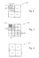
- the subbands are labelled DC, HL3, HH3, LH3, HL2, HH2, LH2, HL1, HH1 and LH1.
- the DC subband block contains the lowest frequency (or DC) coefficients and represents a lowest resolution (size) of the image in the frequency domain.
- the level three (3) subband triplet HL3, HH3 and LH3 together with the DC subband represents a next higher resolution of the image in the frequency domain.
- the DC subband, the level three subband triplet and a level two (2) subband triplet represent another yet higher resolution.
- the collection of subbands, from the DC subband to the LH1 subband represents the highest resolution (or full size) of the digital image in the frequency domain.
- Each coefficient in a subband block corresponds to a spatially contiguous group of pixels in a digital image.
- a coefficient represents a content group of pixels in the spatial domain for a range of frequencies determined by the subband in which the coefficient is located. For example, each coefficient in a level one (1) subband approximately corresponds to a 2x2 groups of pixels of an image, each coefficient in a level two (2) subband approximately corresponds to a 4x4 group of pixels of the image and each coefficient in a level three (3) subband approximately corresponds to an 8x8 group of pixels of the image In general, a coefficient at level-j subband approximately corresponds to 2 j x 2 j groups of pixel values of an image.
- a degree of approximation in the correspondence between a coefficient in a frequency domain and a group of pixels in a spatial domain depends upon a basis set chosen for the DWT. For example, if a Haar basis set is used for the DWT (ie. Haar Transform) an exact reconstruction (or synthesis) of a group of pixels from corresponding coefficient, in the frequency domain, is possible.
- a Haar basis set is used for the DWT (ie. Haar Transform)
- each subband comprises an equal number of tiles and each tile contains one or more coefficients of the corresponding subband.
- a tile in a DC subband block represents a portion of the digital image at a lowest resolution.
- tiles can be chosen to be of constant size. That is containing the same number of coefficients per tile without departing from the scope and spirit of the present invention.
- each tile or group of tiles is/are entropy encoded to achieve a compression of the image.
- entropy decoding predetermined ones of the tiles and synthesising the tiles through an inverse DWT will result in a reconstruction of a predetermined localised portion of the image.
- the relative size of a tile (eg. a quarter of the size of a subband) is predetermined and is typically constrained by a trade-off between compression efficiency, which requires a large tile, and accuracy in localising a reconstruction of a portion of the image, which necessitates a smallest possible tile size.
- a compromise between compression efficiency and localisation of reconstruction is determined for a specified application of the encoding process of Fig. 1.
- An alternate approach to tiling an image in its corresponding frequency domain is to identify regions of pixels in a spatial domain of the image, which when a transformation (i.e. DWT) is applied to each of the regions corresponds to a tiling of the frequency domain.
- a spatial domain of the image is conceptually divided into a plurality of regions, which upon application of predetermined linear transform, results in a tiling of the corresponding frequency domain of the image.
- a frequency domain representation 300 of a 128x128 pixel image comprises an array of 128x128 coefficients partitioned 301 (shown in Fig. 3 by heavy set lines) into subbands 302 in accordance with Fig. 2. Each subband is further partitioned or tiled into four equal non overlapping tiles 303.
- a labelling scheme is presented for each tile in each subband 302.
- a tile in each subband labelled by an ordered pair (m,n) as follows: a top left corner tile is labelled tile (0,0); a top right corner tile is labelled by the ordered pair (0,1); a bottom left corner tile is labelled (1,0); and a bottom right corner tile is labelled (1,1).
- a tile in Fig. 3 is identified both by its subband label and its tile label.
- tile 304 is identified as DC (0,0) since the tile 304 resides in the DC subband and is the top left tile of the subband.
- a next step in encoding process 100 is the DC coding step 104 which entropy encodes each tile of the DC subband block into a bit stream.
- the tiles 303 in each subband block is entropy encoded into the bit stream in raster order.
- each tile of the DC subband is entropy encoded and added to the bit stream in the following order: DC(0,0), DC(0,1), DC(1,0) and DC(1,1).
- Entropy Encoding and decoding processes used in the preferred embodiment of the present invention is described in more detail in the sections herein entitled "Entropy Encoding Process of the Preferred Embodiment” and Entropy Decoding Process of the Preferred Embodiment” respectively.
- Other entropy encoding (decoding) methods may be used to encode (decode) coefficients in each tile without departing from the scope and spirit of the invention.
- a Huffman or Arithmetic encoding (decoding) method can be used to encode (decode) coefficients in each tile.
- a next step in the flow diagram of Fig. 1 is to initialise 105 a level count variable "levelNum" to a value of three (3) corresponding to the number of levels of the DWT.
- tile count variable herein referred to as "tileNum” is initialised 106 to zero (0).
- Variable levelNum and tileNum are loop variables which allow, the encoding process of Fig. 1 to count down through each tile of the AC subbands (i.e. all subbands other than the DC subband which has been previously, entropy coded into the bitstream).
- the tile count variable "tileNum” is incremented 107 at a next step in the flow diagram, which is then followed by three steps: entropy encode HL subband step 108; entropy encode LH subband step 109; and entropy encode HH subband step 110.
- the entropy encode HL subband step 108 perform an entropy encoding of current tile, indicated tileNum, of a current resolution level, indicated by levelNum into the bit stream.
- steps 109 and 110 entropy encode into the bit stream the current tile of the current level of subband LH and HH respectively.
- decision step 111 a check is made to determine if the current tile is the last tile of the current level. If decision step 111 return false (no) the processing is looped 112 back to the increment tileNum" step 107 and the processing of steps 107, 108,109, 110 and 111 is repeated substantially as hereinbefore described with a new current tile. Otherwise, if decision step 111 returns true (yes) processing continues to step 113 where the variable levelNum is decremented.
- decision step 114 a check is made to determine if the current level is a last level processed, that is, levelNum equals zero (0). If the decision step 114 returns false (no) the encoding process of Fig. I is looped back initialise tileNum to zero (0) at step 106, and steps 107 to 114 substantially as hereinbefore described are repeated for a new current level (i.e. the decremented levelNum). Otherwise, decision step 114 returns true (yes), the process 100 ends at step 115 having produced a bit stream encoded in accordance with the preferred embodiment.
- the bit stream resulting from the encoding process 100, described with reference to Fig. 1, can be represented as follows: DC(0,0), DC(0,1), DC(1,0), DC(1,1), HL3(0,0), LH3(0,0) HH3(0,0), HL3(0,1), LH3(0,1), HH3(0,1), HL3(1,0), LH3(1,0), HH3(1,0), HL3(1,1), LH3(1,1), HH3(1,1) HL1(1,1), LH1(1,1) HH1(1,1).
- the header information is not shown in the foregoing expression.
- each tile e.g. DC(0,0) in the foregoing expression is individually entropy encoded.
- HL3(0,0) is to be entropy decoded, to obtain pixel values of an image portion, then so do tiles LH3(0,0) and HH3(0,0) since these tiles relate to the same image portion.
- a corresponding tile for each AC subband block triplet (HL, LH and HH) can be entropy encoded as a single unit.
- This single unit is referred to hereinafter as a "tile triplet" (e.g. HL3(0,0), LH3(0,0) and HH3(0,0) is one such tile triplet).
- Header information at the beginning 501 of the bit stream may include information on; the size of the bit stream; a compression quality parameter; and a compression factor value.
- the head information also includes a plurality of bit stream pointer information to allow a substantially random access of the encoded tiles.
- the pointer information may comprise a pointer to a starting position of each tile in a DC subband and a pointer to a starting position of each tile triplet.
- the pointer information may include a pointer to the starting position of each tile in the bit stream.
- the pointer information is the number of bits per tile or tile triplet which ever is entropy encoded as a single unit.
- the pointer information is the number of bytes per tile triplet, where the tile or tile triplet code is padded so as to be a whole number of bytes.
- Such pointer information is not necessarily an absolute address, but can be a relative address to the starting position of each tile or tile triplet.
- a zero (0) can be recorded as a corresponding relative pointer to the tile (or tile triplet) and no bits are needed in the bit stream for the tile, since it can be determined, from the corresponding pointer information (i.e. zero) and a neighbouring tile size, how many coefficients are zero (0).
- This preferred feature provides additional compression to a bit stream where it is determined that a tile or plurality of tiles consist entirely of zero coefficients.
- the entropy encoded tiles for the DC subband is sequentially arranged in the bit stream 500, followed by entropy encoded tiles for level 3 subbands, level 2 subbands and level I subbands as previously described with reference to Figs 1 - 4.
- An entropy encoded tile (or tile triplet) may require a corresponding tile header information (not shown in Fig. 5) which is used for an entropy encoding or decoding of the tile or tile triplet.
- a maximum bit number "maxbitNumber" indicating a maximium bit plane is required for an entropy encoding/decoding of an array of coefficients.
- the tile requires an associated corresponding tile header information which includes a maxbitNumber for the tile.
- tile and tile triplet are used interchangeably, particularly when referring to entropy encoding or decoding, since the entropy encoding or decoding of a tile triplet is performed, preferably, on a tile by tile basis excepting that a maxbitNumber is determined from the magnitude of largest coefficient in the tile triplet.
- tile header information is arranged in the bit stream 500 at the start of' each corresponding tile, and is independently encoded from the coefficients of each tile.
- the tile header information is entropy encoded by a different entropy coding technique to that used for the coefficient in each tile.
- Huffman encoding can be used for the tile header information, where the coefficients of the corresponding tile are entropy encoded using the entropy coding method of the preferred embodiment.
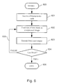
- a flow diagram for decoding a predetermined portion of an image from a compressed image 500 (bit stream) encoded in accordance with the preferred embodiment of the present invention In an initial step 600 a region of an image which is desired from the compressed image 500 (bit stream) and a resolution (or size) of the region is selected.
- Processing continues on a next step 601 where a determination is made as to the number of tiles and which of the tiles encoded into the bit stream 500 are to be decoded to obtain the region of the image selected in the previous step 600.
- the number of tiles decoded from the bit stream 500 is such that a region obtained form the tiles at least encompasses the selected region.
- the pointer information in the header of the bit stream 500 is used to find the tiles in the bit stream 500 to be decoded.
- the tile is passed to a decoding step 603.
- the decoding step 603 first decodes the tile header information for a tile and uses the information (i.e. maxbitNumber) to entropy decode the tile.
- the tile is entropy decoded and outputed.
- a decision step 604 a check is made to determine if a current tile is the last tile of those determined in a previous step 601. If the decision step 604 returns false (no) the flow diagram of Fig. 6 is looped 605 back to step 602 and steps 602 to 604, as hereinbefore described, are repeated. Otherwise, if the decision step 604 returns true (yes) the decoding process of the preferred embodiment ends at step 606 having decoded the desired number of tiles and outputed.
- the decoded tiles are typically outputed to a memory unit and a subband synthesis (ie inverse DWT) is performed before display on a video display device.
- a subband synthesis ie inverse DWT
- bit n the decimal number 9 is represented as 00001001.
- bit 3 is equal to 1
- bits 2, 1, and 0 are equal to 0, 0, and 1, respectively.
- a transform may be represented as a matrix having coefficients arranged in rows and columns, with each coefficient represented by a bit sequence.
- the matrix may be regarded as having three dimensions; one dimension in the now direction; a second dimension in the column direction and a third dimension in the bit sequence direction.
- a plane in this three dimensional space which passes through each bit sequence at the same bitnumber is refereed to as a "bitplane” or "bit plane”.
- the number of bits per coefficient required to represent the possible range of coefficients is determined by the linear transform and the resolution of each pixel (in bits per pixel) in the input image. This range of values for each pixel is typically large relative to the values of most of the transform coefficients, and thus many coefficients have a large number of leading zeros. For example, the number 9 has four leading zeros in an 8-bit representation and has 12 leading zeros in a 16-bit representation.
- the embodiments of the invention provide a method and apparatus of representing (or coding) these leading zeros, for blocks of coefficients, in an efficient manner. The remaining bits and sign of the number are encoded directly without modification.
- the transform coefficients are assumed hereinafter to be represented in an unsigned binary integer form, with a single sign bit. That is, the decimal numbers -9 and 9 are represented with the same bit sequence, namely 10001, with the former having a sign bit equal to 1 to indicate a negative value, and the latter having a sign bit equal to 0 to indicate a positive value. The number of leading zeros is determined by the range of the transform coefficients. In using an integer representation, the coefficients are implicitly already quantised to the nearest integer value, although this is not necessary for the embodiment of the invention. Further, for the purpose of compression, any information contained in fractional bits is normally ignored.
- a tile consists of a set of contiguous image coefficients.
- the term coefficient is used hereinafter interchangeably with pixel, however, as will be well understood by a person skilled in the art, the former is typically used to refer to pixels in a transform domain (eg., a DWT domain).
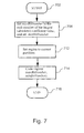
- Fig. 7 is a flow diagram illustrating the entropy encoding method according to the preferred embodiment.
- processing commences using a tile.
- the most significant bit (msb) of the largest absolute value of the transform coefficients is determined from the tile header information and a parameter, maxBitNumber, is set to this coefficient value. For example, if the largest transform coefficient has a binary value of 00001001 (decimal 9), the parameter maxBitNumber is set to 3, since the msb is bit number 3.
- the parameter maxBitNumber may be set to be any value that is larger that the msb of the largest absolute value of the transform coefficients.
- each tile in the triplet is entropy encoded seperately, however a maxBitNumber for the tile triplet is used.
- a maxBitNumber for the tile triplet is used.
- a common maxBitNumber associates each tile in triplet with the tile triplet, since the three tile in the tile triplet are then decoded together.
- Each tile can be processed separately, setting each initial region to the whole tile in question.
- a coding parameter minBitNumber is set to specify the coded image quality.
- this coding parameter specifics the precisions of every coefficient in the transformed image and can be varied as required. For example a minBitNumber of 3 provides a coarser reproduction of the original image than does a value of 1.
- the minBitnumber parameter is typically stored in the header information of the bit stream 500 and defines the compression quality of the entire image.
- each tile is coded by setting an initial region as the whole tile.
- the region is encoded with the maxBitNumber and minBitNumber as parameters. Processing terminates in step 716.
- Fig. 8 is a detailed flow diagram of the procedure "Code region( currentBitNumber, minBitNumber ) " called in step 714 of Fig. 7 for coding each region, where maxBitNumber is provided as the currentBitNumber.
- processing commences.
- the inputs to the region coding process of Fig. 8 include the currentBitNumber and minBitNumber parameters.
- the method is implemented as a recursive technique where the process is able to call itself with a selected region or sub-region.
- the process may implemented in a non-recursive manner without departing from the scope and spirit of the invention.
- decision block 804 a check is made to determine if the currentBitNumber parameter is less than the minBitNumber parameter. If decision block 804 returns true (yes), nothing is done and processing returns to the calling procedure (or parent process) in step 806. This condition indicates that every coefficient in the selected region has a msb number less than minBitNumber . Otherwise, if decision block 804 returns false (no), processing continues at decision block 808.
- decision block 808 a check is made to determine if the selected region is a 1 ⁇ 1 pixel. While this embodiment is described with a predetermined size of 1 ⁇ 1 pixels, it will be apparent to one skilled in the art that different sizes may be practised without departing from the scope and spirit of the invention.
- the predetermined size can be M ⁇ N pixels, where both M and N are positive integers. For example, the predetermined size may be less than or equal to 2 ⁇ 2 pixels or coefficients. If decision block 808 returns true (yes), processing continues at step 810. In step 810, the 1 ⁇ 1 pixel is coded. Again, it will be apparent to one skilled in the art that different predetermined sizes (M ⁇ N pixels) may be practiced.
- the predetermined size may be less than or equal to 2 ⁇ 2 pixels or coefficients.
- this step 810 involves directly outputting the remaining bits above the minBitNumber in the coded representation.
- processing returns to the calling procedure. Otherwise, if decision block 808 returns false (no), the region consists of more than one coefficient and processing continues at decision block 814.
- the selected region is checked to determine if it is significant. That is, the significance at the region is tested.
- the region is said to be insignificant if the msb number of each coefficient in the region is less than the value of the currentBitNumber parameter.
- a mathematical definition is given in Equation (1).
- the region is said to be insignificant if: c ij ⁇ 2", ⁇ i,j ⁇ R , where R denotes the region, and C ij . denotes coefficient (i,j) in this region.
- step 816 a value of 0 (or first token) is output in the coded representation stream, and a recursive call is made in step 817 to the subroutine CodeRegion( currentBitNumber-1,minBitNumber ) where currentBitNumber has been decremented by 1. That is, the next, lower bitplane of the region is selected for processing. Processing then continues at decision block 804, where the region is again processed with the parameters currentBitNumber -1 and minBitNumber. Otherwise, if decision block 814 returns true (yes), that is, the region is significant, processing continues at step 818.
- the step 814 may be replace by a step that outputs currentBitNumber - n zeros, where n is the largest integer for which the region is significant. If n is not less than minBitNumber, the processing goes to step 818. Otherwise the function terminates.
- step 818 a value of 1 (or second token) is output in the coded representation stream.
- step 820 the selected region is partitioned into a predetermined number (preferably, 4) of subregions using a specified partitioning algorithm or process. The partitioning process used is known to the decoder.
- each square region is partitioned in a quad tree type fashion. That is, a region is partitioned preferably into 4 equal-sited (square) sbregions. A subregion is then recursively selected and partitioned again into 4 equal-sized (square) subregion. The selection of a subregion for recursive partitioning substantially depends upon the values of the coeffecients in the subregion and the recursion stops when a desired sized subregion is reached or all the coefficient in a subregion are zero (0).
- This quad tree type partitioning is not always possible depending on the size and shape at the initial region.
- the initial region can be partitioned into a number of square regions, each having dimensions that are a power of 2, and these partitions can be encoded separately. In any case, this initialisation has minimal effect on the overall results if done in an intelligent fashion.
- a different partition may be used that is suitable for a block-based coder.
- each subregion is then coded with the same currentBitNumber and minBitNumber parameters. This is preferably done by means of a recursive call to the procedure "Code region( currentBitNumber , minBitNumber ) of Fig. 8. This coding of subregions may he implemented in parallel or sequentially.
- a transform coefficient is coded by simply outputting the pixel bits from the currentBitNumber to the minBitNumber.
- the entropy encoding method of the preferred embodiment effectively codes the leading zeros of most transform coefficients, while coding the bits from the most significant bit to the predetermined least significant bit, specified by the parameter minBitNumber, and the sign simply as is.
- the preferred embodiment of the present invention advantageously represents the leading zeros. This method is very efficient in certain situations, namely for coding array coefficients skewed in a predetermined manner, and which typically exhibit a large dynamic range. A few coefficients typically have very large values, while most have very small values.
- the magnitude of the coefficients are arranged in the array such that from a largest magnitude coefficients are arranged substantially in descending order of magnitude.
- the minBitNumber is set to 3, for illustrative purposes.
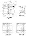
- a tile header (information) is preferably output in the coded representation containing the maxBitNumber. The process of coding the region 1100 then follows.
- a one (1) is output since the region 1100 is significant with respect to bit number 7 (see decision block 804, 808, and 814 and step 818 of Fig. 8).
- the region 1100 is then partitioned into four sub-regions (see step 820 of Fig. 8): the top left region 1110, the top right region 1112, the bottom left region 1114 and the bottom right region 1116 of Fig. 11A.
- Each of the subregions consist of 3 ⁇ 2 coefficients.
- Fig. 11A The sub-regions 1110, 1112, 1114 and 1116 of Fig. 11A are in turn coded in the predefined processing sequence shown of Fig. 11B, where a region 1150 consists of four sub-regions 1150A to 1150D.
- the three arrows illustrated in the diagram indicate the order or sequence of processing, that is, top left sub-region 1150A, top right sub-region 1150B, bottom left sub-region 1150C and bottom right sub-region 1150D, respectively.
- the coefficient value -13 is coded as 00001 with a sign bit 1.
- the coefficient value 3 is coded as 00000 (without a sign bit).
- the coded representation of each coefficient includes the two "1" bits preceding the bits of coefficient "200" between the currentBitNumber and minBitNumber . This completes the coding of the top left sub-region 1110.
- the coded output at this stage is:
- the tile header information is not shown in the foregoing expression.
- the sub-region 1112 is partitioned into the four 1 ⁇ 1 pixels having values - 11, -8, -4 and -3. These decimal values are coded as bit value 1 with sign bit 1, bit value 1 with sign bit 1 and bit values 0 and 0 without sign bits, respectively.
- the coded representation is as follows:
- the bottom left sub-region 1114 is then encoded. A zero (0) is output for each of currentBitNumber equal to 7, 6, 5, and 4, since the region 1114 is insignificant with respect to these bit numbers. A one (1) is output at currentBitNumber equal to 3, since this bitplane is significant with respect to bit number 3.
- the sub-region 1114 is then partitioned into four 1 ⁇ 1 pixels having values 8, 1, 2 and -1. These are coded respectively as binary value 1 with sign bit 0, and binary values 0,0 and 0 without sign bits.
- the bottom right sub-region 1116 having values -2, -2, -3, and -3 is coded.
- the coded representation is as follows: 111100100000100000110000000001111100000011000000000.
- the entropy decoder simply mimics the entropy encoding process to reconstruct the region from the ccoded representation as depicted in Fig. 11C.
- the decoding process can be made "smarter” in a number of ways.
- One such “smarter” way is depicted in Fig. 11D.
- the magnitude of each of the non-zero coefficients is increased by half of 2 to the power of minBitNumber. This is depicted in Fig. 11D.
- the "smart" decoding processing generally reduces the mean square error between the decoded and the original coefficients.
- the encoder can alternatively perform this (type of) operation, thereby leaving the decoder to use the simplest depicted in Fig. 11C.
- Fig. 9 is a flow diagram illustrating a method of decoding tiles entropy encoded with the entropy encoding process of the preferred embodiment
- processing commences using the coded representation.
- decoding of the selected tiles is commenced by setting the region to the whole selected tile.
- the selected region is decoded using the maxBitNumber and minBitNumber parameters. Processing terminates in step 912.
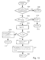
- Fig. 10 is a detailed flow diagram of step 908 of Fig. 9 for decoding each region using procedure call "Decode region( currentBitNumber , minBitNumber )", where maxBitNumber is provided as the currentBitNumber .
- processing commences.
- the inputs to the region decoding process of Fig. 10 are the currentBitNumber and minBitNumber parameters.
- the method is preferably implemented as a recursive technique. However, the process may be implemented in a non-recursive manner without departing from the scope and spirit of the invention.
- decision block 1004 a check is made to determine if the currentBitNumber is less than the minBitNumber. If decision block 1004 returns true (yes), proccessing continues at step 1006, where processing returns to the calling procedure. Otherwise, if decision block 1004 returns false (no), processing continues at decision block 908.
- decision block 1008 a check is made to determine if the selected region has a size of 1 ⁇ 1 pixels. If decision block 1008 returns true (yes), processing continues at step 1010. In step 1010, the 1 ⁇ 1 region is decoded. Likewise, the size may be predetermined and be equal to M ⁇ N pixels, where both M and N are positive integers. For example. the size may be less than or equal to 2 ⁇ 2 pixels or coefficients. Processing then returns to the calling procedure in step 1012. If decision block 1008 returns false (no), processing continues at step 1014. In step 1014, a bit is input from the coded representation.
- decision block 1016 a check is made to determine if the bit is equal to 1, that is, the input is checked to determine if the region is significant. If decision block 1016 returns false (no), processing continues at step 1018. In step 1018, a recursive call is made to the subroutine DeCodeRegion( currentBitNumber-1,minBitNumber ) where currentBitNumber has been decremented by 1, and processing continues at decision block 1004. Otherwise, if decision block 1016 returns true (yes), processing continues at step 1020. In step 1020, the region is partitioned into the predetermined number (preferably, 4) of sub-regions.
- each of the sub-regions is decoded using the currentBitNumber and minBitNumber . In the preferred embodiment, this is carried out by means of a recursive call to the process illustrated in Fig. 10.
- processing returns to the calling procedure.
- the hits output from the significance decisions in the encoder instruct the decoder on which path of the process to take, thus mimicking the encoder.
- the pixels, and possible sign, are decoded by simply reading in the appropriate number of bits ( currentBitNumber to minBitNumber and if some of these are non-zero the sign bit).
- the encoding and decoding processes are preferably practiced using a conventional general-purpose computer, such as the one shown in Fig. 12, wherein the processes described with reference to Figs. 1 to 11 may be implemented as software executing on the computer.
- the steps of the coding and/or decoding methods are effected by instructions in the software that are carried out by the computer.
- the software may be divided into two separate parts; one part for carrying out the encoding and/or decoding methods; and another part to manage the user interface between the latter and the user.
- the software may be stored in a computer readable medium, including the storage devices described below, for example. The software is loaded into the computer from the computer readable medium, and then executed by the computer.
- a computer readable medium having such software or computer programs recorded on it is a computer program product.
- the use of the computer program product in the computer preferably effects an advantageous apparatus for encoding digital images and decoding coded representations of digital images in accordance with the embodiments of the invention.
- a system may be practiced for coding a digital image and decoding the corresponding coded representation of the image, or vice versa.
- the computer system 1200 consists of the computer 1202, a video display 1216, and input devices 1218, 1220.
- the computer system 1200 can have any of a number of other output devices including line printers, laser printers, plotters, and other reproduction devices connected to the computer 1202.
- the computer system 1200 can be connected to one or more other computers via a communication interface 1208c using an appropriate communication channel 1230 such as a modem communications path, a computer network, or the like.
- the computer network may include a local area network (LAN), a wide area network (WAN), an Intranet, and/or the Internet
- the computer 1202 itself consists of a central processing unit(s) 1204, a memory 1206 which may include random access memory (RAM) and read-only memory (ROM), input/output (IO) interfaces 1208a, 1208b, a video interface 1210, and one or more storage devices generally represented by a block 1212 in Fig. 12.
- the storage device(s) 1212 can consist of one or more of the following: a floppy disc, a hard disc drive, a magneto-optical disc drive, CD-ROM, magnetic tape or any other of a number of non-volatile storage devices well known to those skilled in the art.
- Each of the components 1204 to 1212 is typically connected to one or more of the other devices via a bus 114 that in turn can consist of data, address, and control buses.
- the video interface 1210 is connected to the video display 1216 and provides video signals from the computer 1202 for display on the video display 1216.
- User input to operate the computer 1202 can be provided by one or more input devices. For example, an operator can use the keyboard 1218 and/or a pointing device such as the mouse 1220 to provide input to the computer 1202.
- the systems 1200 is simply provided for illustrative purposes and other configurations can be employed without departing from the scope and spirit of the invention.
- Exemplary computers on which the embodiment can be practiced include IBM-PC/ATS or compatibles, one of the Macintosh (TM) family of PCs, Sum Sparcstation (TM), or the like.
- TM Macintosh
- TM Sum Sparcstation
- the foregoing are merely exemplary of the types of computers with which the embodiments of the invention may be practiced.
- the processes of the embodiments, described hereinafter, are resident as software or a program recorded on a hard disk drive (generally depicted as block 1212 in Fig. 12) as the computer readable medium, and read and controlled using the processor 104.
- Intermediate storage of the program and pixel data and any data fetched from the network may be accomplished using the semiconductor memory 1206, possibly in concert with the hard disk drive 1212.
- the program may be supplied to the user encoded on a CD-ROM or a floppy disk (both generally depicted by block 1212), or alternatively could be read by the user from the network via a modem device connected to the computer, for example.
- the software can also be loaded into the computer systems 1200 from other computer readable medium including magnetic tape, a ROM or integrated circuit, a magneto-optical disk, a radio or infra-red transmission channel between the computer and another device, a computer readable card such as a PCMCIA card, and the Internet and Intranets including email transmissions and information recorded on websites and the like.
- the foregoing are merely exemplary of relevant computer readable mediums. Other computer readable mediums may be practiced without departing from the scope and spirit of the invention.
- the method of coding and/or decoding may alternatively be implemented in dedicated hardware such as one or more integrated circuits performing the functions or sub functions of the encoding and decoding.
- dedicated hardware may include graphic processors, digital signal processors, or one or more microprocessors and associated memories.
- the user would encode/decode digital images stored on one or more of the computer readable media previosly described.
- the user may retrieve the digital via the communication channel 1230.
- the encoding process may be performed on a remote computer (not shown), whilst the decoding process is performed on the computer 1202.
- An alternate embodiment is decribed substantially as the preferred embodiment excepting that not all the of multiple resolutions provided by a multi-level subband decomposition of the image are coded efficiently into a bit stream, only a predetermined selected number of levels (resolutions) are a chosen for efficient coding in accordance with the embodiments. That is, for example, three of the four resolutions described with reference to Figs. 2 and 3 are selected as desired resolutions. For instance, if a highest resolution, a second highest resolution and lowest resolution are the only desired resolutions, then with minor modification to the encoding process of Fig. 1, two resolution levels can be combined in the encoding process to provide, efficiently, a single coded resolution. By combining two resolutions in the encoding process described with reference to Fig. 1, the total number of efficiently encoded resolutions is decreased by one. For combined resolution levels, the effective resolution of the combination is equivalent to the highest resolution in the combination.
- bit stream having combined in the bit stream for example level 3 and level 2 subband tile, described with reference to Fig.
- bit streams arrangement of the embodiments advantageously provide an efficient access to one or more tiles representing a localised portion of the image at predetermined resolution.
- all resolutions provided by a subband decomposition of an image can always be retrieved from the bit streams of the embodiments of the present invention at an added cost, in access time, for unravelling lower resolution levels in a combination of resolution levels as described with reference to the alternate embodiment.
- bit streams arrangements of the embodiments of the present invention are advantageous where a bit stream is stored and read from a storage device having a relatively slow data access time for random accesses.
- a further advantage of the bit streams described in the embodiments is that only one pointer access into a bit stream per now of tiles per resolution level at most is required to access a portion of a digital image.
- An offset can be used to address a tile in a now which can be determined from the pointer and the size (number of coefficients in each tile).
- a pointer per spatially related tile, sequentially (contiguously) arranged in the bit stream, per (desired) resolution level at most is required.
- bit stream arrangements can be achieved by combining resolutions (subband levels) into a bit stream in an intelligent manner. For example, to achieve efficient access of portion of an image at only a largest and a smallest resolution in an N-level DWT representation, tiles in subbands which provide resolutions other than the smallest resolution can be combined into a bit stream substantially as described in the alternate embodiment of the present invention.
Landscapes
- Engineering & Computer Science (AREA)
- Multimedia (AREA)
- Signal Processing (AREA)
- Compression Of Band Width Or Redundancy In Fax (AREA)
- Compression Or Coding Systems Of Tv Signals (AREA)
- Compression, Expansion, Code Conversion, And Decoders (AREA)
Applications Claiming Priority (4)
| Application Number | Priority Date | Filing Date | Title |
|---|---|---|---|
| AUPP446898 | 1998-07-03 | ||
| AUPP4468A AUPP446898A0 (en) | 1998-07-03 | 1998-07-03 | An image coding method and apparatus for localized decoding at variable resolutions |
| AUPP574998 | 1998-09-07 | ||
| AUPP5749A AUPP574998A0 (en) | 1998-09-07 | 1998-09-07 | An image coding method and apparatus for localised decoding at multiple resolutions |
Publications (3)
| Publication Number | Publication Date |
|---|---|
| EP0971544A2 true EP0971544A2 (de) | 2000-01-12 |
| EP0971544A3 EP0971544A3 (de) | 2001-04-25 |
| EP0971544B1 EP0971544B1 (de) | 2009-01-07 |
Family
ID=25645818
Family Applications (1)
| Application Number | Title | Priority Date | Filing Date |
|---|---|---|---|
| EP99304937A Expired - Lifetime EP0971544B1 (de) | 1998-07-03 | 1999-06-23 | Vorrichtung und Verfahren zur Bildkodierung für lokalisierte Dekodierung in mehreren Auflösungen |
Country Status (4)
| Country | Link |
|---|---|
| US (2) | US6763139B1 (de) |
| EP (1) | EP0971544B1 (de) |
| JP (2) | JP4420415B2 (de) |
| DE (1) | DE69940238D1 (de) |
Cited By (8)
| Publication number | Priority date | Publication date | Assignee | Title |
|---|---|---|---|---|
| FR2816138A1 (fr) * | 2000-10-27 | 2002-05-03 | Canon Kk | Decodage de donnees numeriques |
| GB2383917A (en) * | 2001-11-21 | 2003-07-09 | Ge Med Sys Information Tech | Method and apparatus for transmission and display of a compressed digitized image |
| EP1401207A2 (de) * | 2002-09-18 | 2004-03-24 | Ricoh Company, Ltd. | Bildverarbeitungsgerät, Bilderzeugungsvorrichtung, Programm, und ein Computer-Speichermedium |
| WO2004080080A1 (en) * | 2003-03-04 | 2004-09-16 | Alcom Algoritmi Compressione Dati S.R.L. | Apparatus and method for compression and decompression of digital data |
| EP1722572A1 (de) * | 2004-02-23 | 2006-11-15 | NEC Corporation | Verfahren und einrichtung zur 2-dimensionalen signalcodierung/-decodierung |
| WO2007058296A1 (ja) | 2005-11-18 | 2007-05-24 | Sony Corporation | 符号化装置および方法、復号装置および方法、並びに、伝送システム |
| US7421136B2 (en) | 1999-11-24 | 2008-09-02 | Ge Medical Systems Information Technologies Inc. | Image tessellation for region-specific coefficient access |
| EP2330587A1 (de) * | 2008-09-30 | 2011-06-08 | Sony Computer Entertainment Inc. | Bildverarbeitungsvorrichtung und bildverarbeitungsverfahren |
Families Citing this family (34)
| Publication number | Priority date | Publication date | Assignee | Title |
|---|---|---|---|---|
| US20020044696A1 (en) * | 1999-11-24 | 2002-04-18 | Sirohey Saad A. | Region of interest high resolution reconstruction for display purposes and a novel bookmarking capability |
| AUPQ982400A0 (en) * | 2000-09-01 | 2000-09-28 | Canon Kabushiki Kaisha | Entropy encoding and decoding |
| JP3984886B2 (ja) * | 2001-09-28 | 2007-10-03 | キヤノン株式会社 | データ変換装置、データ変換方法、コンピュータプログラム、記憶媒体 |
| US20050254718A1 (en) * | 2002-03-04 | 2005-11-17 | Ryozo Setoguchi | Web-oriented image database building/control method |
| US7646927B2 (en) | 2002-09-19 | 2010-01-12 | Ricoh Company, Ltd. | Image processing and display scheme for rendering an image at high speed |
| JP4064196B2 (ja) * | 2002-10-03 | 2008-03-19 | 株式会社リコー | クライアントコンピュータ、サーバコンピュータ、プログラム、記憶媒体、画像データ処理システム及び画像データ処理方法 |
| US7133054B2 (en) * | 2004-03-17 | 2006-11-07 | Seadragon Software, Inc. | Methods and apparatus for navigating an image |
| US7912299B2 (en) * | 2004-10-08 | 2011-03-22 | Microsoft Corporation | System and method for efficiently encoding data |
| US7546419B2 (en) * | 2004-06-01 | 2009-06-09 | Aguera Y Arcas Blaise | Efficient data cache |
| US7042455B2 (en) * | 2003-05-30 | 2006-05-09 | Sand Codex Llc | System and method for multiple node display |
| US7254271B2 (en) * | 2003-03-05 | 2007-08-07 | Seadragon Software, Inc. | Method for encoding and serving geospatial or other vector data as images |
| US7930434B2 (en) * | 2003-03-05 | 2011-04-19 | Microsoft Corporation | System and method for managing communication and/or storage of image data |
| US7075535B2 (en) * | 2003-03-05 | 2006-07-11 | Sand Codex | System and method for exact rendering in a zooming user interface |
| US20060235941A1 (en) * | 2005-03-29 | 2006-10-19 | Microsoft Corporation | System and method for transferring web page data |
| EP1927084A4 (de) | 2005-09-23 | 2009-07-01 | Slipstream Data Inc | Verfahren, system und computerprogrammprodukt zur entropie eingeschränkten farbaufteilung für palettenbilder mit pixelweiser aufteilung |
| JP2007318694A (ja) * | 2006-05-29 | 2007-12-06 | Canon Inc | 画像処理方法、画像処理装置 |
| KR100834669B1 (ko) * | 2006-10-20 | 2008-06-02 | 삼성전자주식회사 | 썸네일 이미지 생성을 위한 웨이블릿 변환 기반 이미지부호화기, 복호화기 및 그 방법 |
| AU2006246497B2 (en) * | 2006-11-30 | 2010-02-11 | Canon Kabushiki Kaisha | Method and apparatus for hybrid image compression |
| JPWO2008093698A1 (ja) * | 2007-01-31 | 2010-05-20 | ソニー株式会社 | 情報処理装置および方法 |
| JP2009122847A (ja) * | 2007-11-13 | 2009-06-04 | Ricoh Co Ltd | ファイルアクセス装置 |
| US8116580B2 (en) * | 2008-05-12 | 2012-02-14 | Lexmark International, Inc. | Embedded high frequency image details |
| US8391638B2 (en) | 2008-06-04 | 2013-03-05 | Microsoft Corporation | Hybrid image format |
| US20100035217A1 (en) * | 2008-08-11 | 2010-02-11 | David Kasper | System and method for transmission of target tracking images |
| JP5037574B2 (ja) * | 2009-07-28 | 2012-09-26 | 株式会社ソニー・コンピュータエンタテインメント | 画像ファイル生成装置、画像処理装置、画像ファイル生成方法、および画像処理方法 |
| WO2011019625A1 (en) * | 2009-08-10 | 2011-02-17 | Telcordia Technologies, Inc. | System and method for multi-resolution information filtering |
| US8462392B2 (en) * | 2009-08-13 | 2013-06-11 | Telcordia Technologies, Inc. | System and method for multi-resolution information filtering |
| KR20120009618A (ko) * | 2010-07-19 | 2012-02-02 | 에스케이 텔레콤주식회사 | 주파수변환단위 분할부호화 방법 및 장치와 이를 이용한 영상 부호화/복호화 방법 및 장치 |
| US10091506B2 (en) * | 2015-06-11 | 2018-10-02 | Sony Corporation | Data-charge phase data compression architecture |
| US10027968B2 (en) * | 2015-06-12 | 2018-07-17 | Sony Corporation | Data-charge phase data compression tool |
| US10303498B2 (en) | 2015-10-01 | 2019-05-28 | Microsoft Technology Licensing, Llc | Performance optimizations for emulators |
| US11327802B2 (en) * | 2019-07-31 | 2022-05-10 | Microsoft Technology Licensing, Llc | System and method for exporting logical object metadata |
| US11403100B2 (en) | 2020-08-31 | 2022-08-02 | Microsoft Technology Licensing, Llc | Dual architecture function pointers having consistent reference addresses |
| US11042422B1 (en) | 2020-08-31 | 2021-06-22 | Microsoft Technology Licensing, Llc | Hybrid binaries supporting code stream folding |
| US11231918B1 (en) | 2020-08-31 | 2022-01-25 | Microsoft Technologly Licensing, LLC | Native emulation compatible application binary interface for supporting emulation of foreign code |
Citations (4)
| Publication number | Priority date | Publication date | Assignee | Title |
|---|---|---|---|---|
| GB2281465A (en) * | 1993-08-27 | 1995-03-01 | Sony Uk Ltd | Image data compression using sub-band coding with sub-bands having different numbers of frequency components |
| GB2303031A (en) * | 1995-06-30 | 1997-02-05 | Ricoh Kk | Reversible wavelet transform and embedded codestream manipulation |
| WO1998011728A1 (en) * | 1996-06-24 | 1998-03-19 | Wde Inc. | Method, apparatus and system for compressing data |
| WO1998019274A1 (en) * | 1996-10-28 | 1998-05-07 | Commonwealth Scientific And Industrial Research Organisation | Image encoding |
Family Cites Families (13)
| Publication number | Priority date | Publication date | Assignee | Title |
|---|---|---|---|---|
| JPS6316773A (ja) * | 1986-07-08 | 1988-01-23 | Mitsubishi Electric Corp | Crtモニタ装置 |
| EP0522219B1 (de) | 1991-07-11 | 1997-10-15 | International Business Machines Corporation | Verbessertes Verfahren zur Teilbandbildkodierung und Einrichtung zur Durchführung dieses Verfahrens |
| JPH05260512A (ja) * | 1992-03-12 | 1993-10-08 | Hitachi Ltd | 画像信号の記録再生装置 |
| GB9206860D0 (en) | 1992-03-27 | 1992-05-13 | British Telecomm | Two-layer video coder |
| US6141446A (en) * | 1994-09-21 | 2000-10-31 | Ricoh Company, Ltd. | Compression and decompression system with reversible wavelets and lossy reconstruction |
| JP3577794B2 (ja) * | 1995-07-18 | 2004-10-13 | ソニー株式会社 | データ復号化装置 |
| JP3516534B2 (ja) * | 1995-08-31 | 2004-04-05 | シャープ株式会社 | 映像情報符号化装置及び映像情報復号化装置 |
| US5682152A (en) * | 1996-03-19 | 1997-10-28 | Johnson-Grace Company | Data compression using adaptive bit allocation and hybrid lossless entropy encoding |
| US5668599A (en) * | 1996-03-19 | 1997-09-16 | International Business Machines Corporation | Memory management for an MPEG2 compliant decoder |
| FR2755818A1 (fr) | 1996-11-08 | 1998-05-15 | Canon Kk | Codage de signal numerique par decomposition en sous-bandes de frequence et quantification vectorielle a etats finis |
| US6326965B1 (en) * | 1998-04-14 | 2001-12-04 | International Business Machines Corp. | Interactive representation and retrieval of multi-dimensional data using view elements |
| US6325965B1 (en) * | 1998-11-02 | 2001-12-04 | Sumitomo Special Metals Co., Ltd. | Forming method and forming apparatus |
| US6314452B1 (en) * | 1999-08-31 | 2001-11-06 | Rtimage, Ltd. | System and method for transmitting a digital image over a communication network |
-
1999
- 1999-06-22 US US09/337,533 patent/US6763139B1/en not_active Expired - Lifetime
- 1999-06-22 JP JP17598999A patent/JP4420415B2/ja not_active Expired - Fee Related
- 1999-06-23 DE DE69940238T patent/DE69940238D1/de not_active Expired - Lifetime
- 1999-06-23 EP EP99304937A patent/EP0971544B1/de not_active Expired - Lifetime
-
2004
- 2004-01-26 US US10/763,213 patent/US7088866B2/en not_active Expired - Fee Related
-
2006
- 2006-06-14 JP JP2006165343A patent/JP4208900B2/ja not_active Expired - Fee Related
Patent Citations (4)
| Publication number | Priority date | Publication date | Assignee | Title |
|---|---|---|---|---|
| GB2281465A (en) * | 1993-08-27 | 1995-03-01 | Sony Uk Ltd | Image data compression using sub-band coding with sub-bands having different numbers of frequency components |
| GB2303031A (en) * | 1995-06-30 | 1997-02-05 | Ricoh Kk | Reversible wavelet transform and embedded codestream manipulation |
| WO1998011728A1 (en) * | 1996-06-24 | 1998-03-19 | Wde Inc. | Method, apparatus and system for compressing data |
| WO1998019274A1 (en) * | 1996-10-28 | 1998-05-07 | Commonwealth Scientific And Industrial Research Organisation | Image encoding |
Non-Patent Citations (2)
| Title |
|---|
| DE QUEIROZ R ET AL: "WAVELET TRANSFORMS IN A JPEG-LIKE IMAGE CODER" IEEE TRANSACTIONS ON CIRCUITS AND SYSTEMS FOR VIDEO TECHNOLOGY,US,IEEE INC. NEW YORK, vol. 7, no. 2, 1 April 1997 (1997-04-01), pages 419-424, XP000687660 ISSN: 1051-8215 * |
| SEMENTILLI P J ET AL: "WAVELET TCQ: SUBMISSION TO JPEG-2000" PROCEEDINGS OF THE SPIE, XP000852851 * |
Cited By (22)
| Publication number | Priority date | Publication date | Assignee | Title |
|---|---|---|---|---|
| US7474795B2 (en) | 1999-11-24 | 2009-01-06 | Ge Medical Systems Information Technologies, Inc. | Method and apparatus for transmission and display of a compressed digitalized image |
| US7421136B2 (en) | 1999-11-24 | 2008-09-02 | Ge Medical Systems Information Technologies Inc. | Image tessellation for region-specific coefficient access |
| US7236637B2 (en) | 1999-11-24 | 2007-06-26 | Ge Medical Systems Information Technologies, Inc. | Method and apparatus for transmission and display of a compressed digitized image |
| US6937769B2 (en) | 2000-10-27 | 2005-08-30 | Canon Kabushiki Kaisha | Decoding of digital data |
| FR2816138A1 (fr) * | 2000-10-27 | 2002-05-03 | Canon Kk | Decodage de donnees numeriques |
| GB2383917B (en) * | 2001-11-21 | 2006-05-03 | Ge Med Sys Information Tech | Method and apparatus for transmission and display of a compressed digitized image |
| GB2383917A (en) * | 2001-11-21 | 2003-07-09 | Ge Med Sys Information Tech | Method and apparatus for transmission and display of a compressed digitized image |
| EP1401207A3 (de) * | 2002-09-18 | 2004-05-26 | Ricoh Company, Ltd. | Bildverarbeitungsgerät, Bilderzeugungsvorrichtung, Programm, und ein Computer-Speichermedium |
| US7362904B2 (en) | 2002-09-18 | 2008-04-22 | Ricoh Company, Ltd. | Image processing device, image forming apparatus, program, and storing medium |
| EP1401207A2 (de) * | 2002-09-18 | 2004-03-24 | Ricoh Company, Ltd. | Bildverarbeitungsgerät, Bilderzeugungsvorrichtung, Programm, und ein Computer-Speichermedium |
| WO2004080080A1 (en) * | 2003-03-04 | 2004-09-16 | Alcom Algoritmi Compressione Dati S.R.L. | Apparatus and method for compression and decompression of digital data |
| US8031951B2 (en) | 2004-02-23 | 2011-10-04 | Nec Corporation | 2-dimensional signal encoding/decoding method and device |
| EP1722572A1 (de) * | 2004-02-23 | 2006-11-15 | NEC Corporation | Verfahren und einrichtung zur 2-dimensionalen signalcodierung/-decodierung |
| US8265402B2 (en) | 2004-02-23 | 2012-09-11 | Nec Corporation | 2 dimensional signal encoding/decoding method and device |
| EP1722572A4 (de) * | 2004-02-23 | 2010-04-28 | Nec Corp | Verfahren und einrichtung zur 2-dimensionalen signalcodierung/-decodierung |
| EP1901544A1 (de) * | 2005-11-18 | 2008-03-19 | Sony Corporation | Kodiervorrichtung und -verfahren, zusammensetzungsvorrichtung und -verfahren und übertragungssystem |
| EP1901544A4 (de) * | 2005-11-18 | 2011-03-30 | Sony Corp | Kodiervorrichtung und -verfahren, zusammensetzungsvorrichtung und -verfahren und übertragungssystem |
| WO2007058296A1 (ja) | 2005-11-18 | 2007-05-24 | Sony Corporation | 符号化装置および方法、復号装置および方法、並びに、伝送システム |
| EP2330587A1 (de) * | 2008-09-30 | 2011-06-08 | Sony Computer Entertainment Inc. | Bildverarbeitungsvorrichtung und bildverarbeitungsverfahren |
| CN102165515A (zh) * | 2008-09-30 | 2011-08-24 | 索尼计算机娱乐公司 | 图像处理装置以及图像处理方法 |
| EP2330587A4 (de) * | 2008-09-30 | 2012-02-01 | Sony Computer Entertainment Inc | Bildverarbeitungsvorrichtung und bildverarbeitungsverfahren |
| US8878869B2 (en) | 2008-09-30 | 2014-11-04 | Sony Corporation | Image processing device and image processing method |
Also Published As
| Publication number | Publication date |
|---|---|
| EP0971544A3 (de) | 2001-04-25 |
| US7088866B2 (en) | 2006-08-08 |
| DE69940238D1 (de) | 2009-02-26 |
| JP4420415B2 (ja) | 2010-02-24 |
| JP4208900B2 (ja) | 2009-01-14 |
| US6763139B1 (en) | 2004-07-13 |
| EP0971544B1 (de) | 2009-01-07 |
| JP2000036959A (ja) | 2000-02-02 |
| JP2006304345A (ja) | 2006-11-02 |
| US20040170332A1 (en) | 2004-09-02 |
Similar Documents
| Publication | Publication Date | Title |
|---|---|---|
| EP0971544B1 (de) | Vorrichtung und Verfahren zur Bildkodierung für lokalisierte Dekodierung in mehreren Auflösungen | |
| US6163626A (en) | Method for digital image compression | |
| US6263110B1 (en) | Method for data compression | |
| US6389074B1 (en) | Method and apparatus for digital data compression | |
| US6266414B1 (en) | Method for digital data compression | |
| US6259819B1 (en) | Efficient method of image compression comprising a low resolution image in the bit stream | |
| US6804402B2 (en) | Method and apparatus for hierarchically encoding and decoding an image | |
| JP3653183B2 (ja) | ウェーブレット係数再構成処理方法及び装置、並びに記録媒体 | |
| US6266450B1 (en) | Encoding method and apparatus | |
| US6347157B2 (en) | System and method for encoding a video sequence using spatial and temporal transforms | |
| US6411736B1 (en) | Method and apparatus for decoding | |
| AU736469B2 (en) | An image coding method and apparatus for localized decoding at multiple resolutions | |
| AU708489B2 (en) | A method and apparatus for digital data compression | |
| AU725719B2 (en) | A method of digital image compression | |
| AU728938B2 (en) | A method for data compression | |
| AU719749B2 (en) | A method for digital data compression | |
| AU740066B2 (en) | Method and apparatus for hierarchical encoding or decoding video images | |
| AU714202B2 (en) | A method for digital image compression | |
| AU727434B2 (en) | Method and apparatus for decoding | |
| AU727869B2 (en) | An efficient method of image compression comprising a low resolution image in the bit stream | |
| AU2129499A (en) | A method and apparatus for hierarchical encoding and decoding an image |
Legal Events
| Date | Code | Title | Description |
|---|---|---|---|
| PUAI | Public reference made under article 153(3) epc to a published international application that has entered the european phase |
Free format text: ORIGINAL CODE: 0009012 |
|
| AK | Designated contracting states |
Kind code of ref document: A2 Designated state(s): DE FR GB IT NL |
|
| AX | Request for extension of the european patent |
Free format text: AL;LT;LV;MK;RO;SI |
|
| PUAL | Search report despatched |
Free format text: ORIGINAL CODE: 0009013 |
|
| AK | Designated contracting states |
Kind code of ref document: A3 Designated state(s): AT BE CH CY DE DK ES FI FR GB GR IE IT LI LU MC NL PT SE |
|
| AX | Request for extension of the european patent |
Free format text: AL;LT;LV;MK;RO;SI |
|
| 17P | Request for examination filed |
Effective date: 20010910 |
|
| AKX | Designation fees paid |
Free format text: DE FR GB IT NL |
|
| GRAP | Despatch of communication of intention to grant a patent |
Free format text: ORIGINAL CODE: EPIDOSNIGR1 |
|
| GRAS | Grant fee paid |
Free format text: ORIGINAL CODE: EPIDOSNIGR3 |
|
| GRAA | (expected) grant |
Free format text: ORIGINAL CODE: 0009210 |
|
| AK | Designated contracting states |
Kind code of ref document: B1 Designated state(s): DE FR GB IT NL |
|
| REG | Reference to a national code |
Ref country code: GB Ref legal event code: FG4D |
|
| REF | Corresponds to: |
Ref document number: 69940238 Country of ref document: DE Date of ref document: 20090226 Kind code of ref document: P |
|
| PLBE | No opposition filed within time limit |
Free format text: ORIGINAL CODE: 0009261 |
|
| STAA | Information on the status of an ep patent application or granted ep patent |
Free format text: STATUS: NO OPPOSITION FILED WITHIN TIME LIMIT |
|
| 26N | No opposition filed |
Effective date: 20091008 |
|
| PGFP | Annual fee paid to national office [announced via postgrant information from national office to epo] |
Ref country code: NL Payment date: 20120620 Year of fee payment: 14 |
|
| PGFP | Annual fee paid to national office [announced via postgrant information from national office to epo] |
Ref country code: IT Payment date: 20120611 Year of fee payment: 14 |
|
| PGFP | Annual fee paid to national office [announced via postgrant information from national office to epo] |
Ref country code: FR Payment date: 20120712 Year of fee payment: 14 |
|
| REG | Reference to a national code |
Ref country code: NL Ref legal event code: V1 Effective date: 20140101 |
|
| REG | Reference to a national code |
Ref country code: FR Ref legal event code: ST Effective date: 20140228 |
|
| PG25 | Lapsed in a contracting state [announced via postgrant information from national office to epo] |
Ref country code: NL Free format text: LAPSE BECAUSE OF NON-PAYMENT OF DUE FEES Effective date: 20140101 |
|
| PG25 | Lapsed in a contracting state [announced via postgrant information from national office to epo] |
Ref country code: FR Free format text: LAPSE BECAUSE OF NON-PAYMENT OF DUE FEES Effective date: 20130701 Ref country code: IT Free format text: LAPSE BECAUSE OF NON-PAYMENT OF DUE FEES Effective date: 20130623 |
|
| PGFP | Annual fee paid to national office [announced via postgrant information from national office to epo] |
Ref country code: DE Payment date: 20150630 Year of fee payment: 17 Ref country code: GB Payment date: 20150626 Year of fee payment: 17 |
|
| REG | Reference to a national code |
Ref country code: DE Ref legal event code: R119 Ref document number: 69940238 Country of ref document: DE |
|
| GBPC | Gb: european patent ceased through non-payment of renewal fee |
Effective date: 20160623 |
|
| PG25 | Lapsed in a contracting state [announced via postgrant information from national office to epo] |
Ref country code: DE Free format text: LAPSE BECAUSE OF NON-PAYMENT OF DUE FEES Effective date: 20170103 |
|
| PG25 | Lapsed in a contracting state [announced via postgrant information from national office to epo] |
Ref country code: GB Free format text: LAPSE BECAUSE OF NON-PAYMENT OF DUE FEES Effective date: 20160623 |