EP0971455B1 - Electrical connector - Google Patents
Electrical connector Download PDFInfo
- Publication number
- EP0971455B1 EP0971455B1 EP19990112519 EP99112519A EP0971455B1 EP 0971455 B1 EP0971455 B1 EP 0971455B1 EP 19990112519 EP19990112519 EP 19990112519 EP 99112519 A EP99112519 A EP 99112519A EP 0971455 B1 EP0971455 B1 EP 0971455B1
- Authority
- EP
- European Patent Office
- Prior art keywords
- locking
- plug connector
- connector according
- latching
- projection
- Prior art date
- Legal status (The legal status is an assumption and is not a legal conclusion. Google has not performed a legal analysis and makes no representation as to the accuracy of the status listed.)
- Expired - Lifetime
Links
Images


Classifications
-
- H—ELECTRICITY
- H01—ELECTRIC ELEMENTS
- H01R—ELECTRICALLY-CONDUCTIVE CONNECTIONS; STRUCTURAL ASSOCIATIONS OF A PLURALITY OF MUTUALLY-INSULATED ELECTRICAL CONNECTING ELEMENTS; COUPLING DEVICES; CURRENT COLLECTORS
- H01R13/00—Details of coupling devices of the kinds covered by groups H01R12/70 or H01R24/00 - H01R33/00
- H01R13/62—Means for facilitating engagement or disengagement of coupling parts or for holding them in engagement
- H01R13/629—Additional means for facilitating engagement or disengagement of coupling parts, e.g. aligning or guiding means, levers, gas pressure electrical locking indicators, manufacturing tolerances
- H01R13/62933—Comprising exclusively pivoting lever
- H01R13/62966—Comprising two pivoting levers
Definitions
- the invention relates to an electrical connector having the features of the preamble of claim 1.
- the invention has for its object to simplify an electrical connector of the type mentioned in terms of construction and operation.
- the features of claim 1 comprises as a connector parts a lower part and an attachable to the lower part top electrical connector preferably two on both sides pivotally mounted on one of the connector parts, lockable with the other connector part in the manner of a Vorreibers and respectively by a common handle part to a single locking bracket interconnected locking leg.
- Their pivot planes are aligned approximately parallel in the insertion direction of the connector.
- the one-armed lever type locking arms are formed by approximately parallel to each other flat parts and engage behind with their unrelated lever or locking ends each extending transversely to the direction of insertion and thus protruding from the other connector part in the pivot planes locking projection, in particular a locking pin.
- the locking legs are secured by spring pressure system or spring pressure, which is generated by a one-piece with the respective locking leg, from the surface extension angled spring arm is generated, wherein the spring arm in the locking position engages around the locking projection.
- the locking legs act on the respective locking projection directly with a side edge.
- On the connector parts acting tensile forces are thus on the locking projection and the bottom or side edge of the locking leg in the or the locking bracket - and thus not in the spring arm - initiated.
- each locking leg of the locking bracket acts directly on the locking projection of the other connector part, in parallel to also acting directly on the locking projection, coupled with it spring pressure. This is made possible by a corresponding one-piece design of the spring arm with the locking leg.
- the locking safety is advantageously increased by a trough of the spring arm and can be improved by a half the diameter of the locking projection, in particular the pin diameter, approximately corresponding radius of the Ausmuldung.
- a connecting web between a Veniegelungsschenkel and its spring arm is connected only to a holding end of the boom. From this holding end of the spring arm is then in the direction approximately parallel to the surface extension of the locking leg.
- An important aspect for the user-friendliness of the connector is the positional fixing of the locking bracket in the open position.
- This aspect relates to the pivotal position of the locking bracket relative to the associated connector part and is therefore fundamentally independent of the structural design of the locking elements to be locked together of the locking bracket and the associated connector part.
- a fixing in position of the locking bracket in the open state by means of a Rastgehemmes is advantageous for the case that both connector parts "flying" are put together should and when a locking bracket prevented by its pivotal position mating. This is the case when the one or more locking brackets fall on the contact area of their connector part. Then they must first be swung away from the contact area, in order to allow unhindered mating of the two connector parts. To solve this problem is used in the unlocking position of a locking bracket whose pivotal movement relative to the associated connector part inhibiting Rastgehemme.
- a Rasthemmung at both ends of the pivoting range of the locking bracket i. provided in locking and unlocking position.
- the connector contains as connector parts, the lower part 1 and the plugged-on upper part 2.
- the arranged within the two connector parts 1.2 contact parts are irrelevant to the invention and therefore not shown.
- a locking bracket 3 is pivotally mounted on both sides.
- the locking bracket 3 each have two on both sides of the lower part 1 pivotally mounted locking leg 4, which are interconnected by a common handle portion 5 to the U-shaped in plan view, one-piece locking bracket 3.
- the pivot planes of the locking legs 4 are approximately parallel to the extending in the insertion direction 6 central longitudinal plane 7 of the connector. The pivot planes are thus parallel to the image plane of FIGS. 1, 3 and 6 and perpendicular to the image plane of FIGS. 2, 4 and 5.
- the one-armed lever type locking leg 4 are each pivotally mounted to pivotally connected to the lower part 1 pivot axes 8.
- the pivot axes 8 are formed by stub axle 9, which protrude on both sides of the flanks 10 of the lower part 1.
- the locking legs 4 are pivotally mounted with its inner end on the axle stubs or bearing pin 9 of the lower part 1.
- the one bearing end 11 and the other locking end 12 are the free ends of the legs of an angular shape with the angle peak (side view in FIGS. 1 and 3) as a handle part 5. This angle shape can also be referred to as a V-shape.
- each locking leg 4 is operatively a one-armed lever, which cooperates by its locking end 12 with the locking projection 13 formed by a locking projection of the lower part 1 in the manner of a Vorreibers.
- Fig. 1, right and Fig. 3 acts on the locking leg 4 with the inner side edge 14 of the locking end 12 associated V-leg immediately the circumference of the locking pin 13, while in the open position the locking pin 13 for unimpeded release of the upper part 2 from the lower part 1 releases ( Figure 1 left).
- the spring arm 15 acts in the locking position with its facing surface the locking pin 13 from above and thereby forms a hammer. It may be a leaf spring effect Reibgehemme. In the embodiment, this is a Formgehemme in that the spring arm 15 is tolerated on its the locking pin 13 side facing. If here the boom is referred to as a spring arm 15, it does not have to mean that in addition it must exert a spring action on the locking pin 13 in the locking position.
- the spring arm 15 is integrally connected by a in the direction of the pivot axis 8 from its holding end 18 inwardly outgoing connecting web 17 with the locking leg 4 in the region of the locking end 12. From the holding end 18 in the region of the connecting web 17 of the boom 15 is in the direction approximately parallel to the surface extension of the locking leg 4 acting on the connector parts 1.2 tensile forces are not introduced via the spring arm 15, but on the lower or side edge 14 of the locking leg 4 - and on the pin-shaped locking projection 13 - in the respective locking bracket 3 ,
- the locking bracket 3 and its locking leg 4 In at least the unlocking position of the locking bracket 3 and its locking leg 4 is a pivoting movement with respect to the pivot-bearing lower part 1 inhibiting Rastgehemme effective.
- the effectiveness extends to the storage area between the locking leg 4 and the journal bearing it 9 of the lower part 1.
- a bearing sleeve 20 In the locking leg 4 is rotatably a bearing sleeve 20 is inserted. It surrounds the shell of the stub axle 9 with its inner cylinder jacket 23. The locking catches is effective between the cap 22 and the front end 21 of the bearing pin 9.
- the bearing sleeve 20 is formed by a plastic part which is rotatably connected by a positive locking 24 with the locking leg 4.
- the longitudinal rib 24 extends substantially radially appropriate over the entire diameter of the bearing pin 9. It has the cross-sectional shape of a wedge whose flanks converge in the direction of the bearing pin 9 and thus form ramps.
- the plastic material of the closure caps 22 is of a spring elasticity, which is sufficient for the generation of a sufficient, oriented in the direction of the end face 21 of the bearing pin 9 spring pressure.
- This spring action is used to engage the longitudinal rib 25 in a over the end face 21 extending notch 26 when the locking leg 4 is in such a rotational position on the stub axle 9, that the longitudinal rib 25 is in angular overlap with the notch 26.
- the notch 26 extends suitably over the entire diameter of the journal 9. Your Angular position is chosen so that it corresponds to the angular position of the longitudinal rib 25 in the open position of the locking bracket 3.
- a second notch 27 is disposed on the end face 21 of the journal 9 in a different angular position, which is associated with the locking position of the locking bracket 3 and the locking leg 4. The notch 27 thereby ensures in the locking position together with the longitudinal rib 25 for a second Rasthemmung in addition to the locking pin formed by the interaction of the spring arm 15 with the locking pin 13.
- the locking pin 13 on the upper part 2 and the bearing pin 9 on the lower part 1 are preferably identical in terms of shape and arrangement.
- the locking bracket 3 can be optionally mounted on the upper part 2.
- the bearing pin 9 on the lower part 1 as a locking pin for the locking bracket 3 is effective.
Landscapes
- Details Of Connecting Devices For Male And Female Coupling (AREA)
- Buckles (AREA)
Description
Die Erfindung betrifft einen elektrischen Steckverbinder mit den Merkmalen des Oberbegriffs des Anspruches 1.The invention relates to an electrical connector having the features of the preamble of
Bei einem aus DE 195 08 605 C1 bekannten elektrischen Steckverbinder erfolgt in Verriegelungsstellung die Beaufschlagung der Verriegelungsvorsprünge des einen Steckverbinderteiles durch den am anderen Steckverbinderteil verschwenkbar gelagerten Verriegelungsbügel mittelbar über ein zwischen den Verriegelungsschenkeln des Verriegelungsbügels und den Verriegelungsvorsprüngen gesondert angeordnetes Federelement. Jeweils ein Verriegelungsschenkel des Verriegelungsbügels beaufschlagt dieses Federelement, welches in Verriegelungsstellung den Beaufschlagungsdruck in Form eines Federdruckes auf jeweils einen Verriegelungsvorsprung überträgt.In one known from DE 195 08 605 C1 electrical connector takes place in the locking position, the loading of the locking projections of a connector part by the pivotally mounted on the other connector part locking clip indirectly via a between the locking legs of the locking bracket and the locking projections separately arranged spring element. In each case, a locking leg of the locking bracket acts on this spring element, which transmits in the locking position, the loading pressure in the form of a spring pressure on a respective locking projection.
Demgegenüber beaufschlagt ein aus der DE 196 33 827 C1 bekannter Verriegelungsbügel für eine Steckvorrichtung mit seiner Seiten- oder Unterkante den entsprechenden Verriegelungsvorsprung unmittelbar. Bei dieser Steckverbindung zwischen einem Steckgehäuse und einem Anbaugehäuse wird die zur Erzeugung eines sicheren Halts des Verriegelungsbügels in der Verriegelungsstellung erforderliche Druckbeaufschlagung von einer zwischen den Gehäusen vorgesehenen Gummidichtung übernommen.In contrast acts on a known from DE 196 33 827 C1 locking bracket for a plug-in device with its side or bottom edge of the corresponding locking projection directly. In this connector between a plug housing and a mounting housing required for generating a secure hold of the locking bracket in the locking position pressurization is taken over by a provided between the housings rubber seal.
Der Erfindung liegt die Aufgabe zugrunde, einen elektrischen Steckverbinder der eingangs genannten Art in baulicher Hinsicht und bedienungstechnisch zu vereinfachen.The invention has for its object to simplify an electrical connector of the type mentioned in terms of construction and operation.
Diese Aufgabe wird erfindungsgemäß gelöst durch die Merkmale des Anspruchs 1. Dazu umfaßt der als Steckverbinderteile ein Unterteil und ein auf das Unterteil aufsteckbares Oberteil aufweisende elektrische Steckverbinder vorzugsweise zwei beidseitig an einem der Steckverbinderteile schwenkbar gelagerte, mit dem anderen Steckverbinderteil nach Art eines Vorreibers verriegelbare und jeweils durch ein gemeinsames Griffteil zu einem einheitlichen Verriegelungsbügel miteinander verbundene Verriegelungsschenkel. Deren Schwenkebenen sind etwa parallel in Steckrichtung des Steckverbinders ausgerichtet. Die nach Art einarmiger Hebel wirksamen Verriegelungsschenkel sind durch etwa zueinander parallele Flachteile gebildet und hintergreifen mit ihren ungelagerten Hebel- oder Verriegelungsenden jeweils einen quer zur Steckrichtung verlaufenden und somit aus dem anderen Steckverbinderteil in die Schwenkebenen hineinstehenden Verriegelungsvorsprung, insbesondere einen Verriegelungszapfen. In der Hintergriffstellung sind die Verriegelungsschenkel durch Federdruckanlage oder Federdruck gesichert, der durch einen mit dem jeweiligen Verriegelungsschenkel einstückigen, aus dessen Flächenerstreckung abgewinkelten Federausleger erzeugt wird, wobei der Federausleger in Verriegelungsstellung den Verriegelungsvorsprung umgreift.This object is achieved according to the invention by the features of
Dabei beaufschlagen die Verriegelungsschenkel den jeweiligen Verriegelungsvorsprung unmittelbar mit einer Seitenkante. Der zapfen- oder bolzenförmige Verriegelungsvorsprung, an dem die Seitenkante des Verriegelungsschenkels in Verriegelungsstellung tangential anliegt, ragt daher über den Verriegelungsschenkel hinaus, oder fluchtet zumindest mit diesem. Auf die Steckverbinderteile wirkende Zugkräfte werden somit über den Verriegelungsvorsprung und die Unter- oder Seitenkante des Verriegelungsschenkels in den oder die Verriegelungsbügel - und somit nicht in den Federausleger - eingeleitet.The locking legs act on the respective locking projection directly with a side edge. The peg-shaped or bolt-shaped locking projection, on which the side edge of the locking leg bears tangentially in the locking position, therefore projects beyond the locking leg, or at least in alignment therewith. On the connector parts acting tensile forces are thus on the locking projection and the bottom or side edge of the locking leg in the or the locking bracket - and thus not in the spring arm - initiated.
Durch die erfindungsgemäße Ausbildung der Verriegelung des elektrischen Steckverbinders wirkt jeder Verriegelungsschenkel des Verriegelungsbügels unmittelbar auf den Verriegelungsvorsprung des anderen Steckverbinderteiles ein, und zwar parallel zum ebenfalls unmittelbar auf den Verriegelungsvorsprung einwirkenden, mit ihm gekoppelten Federdruck. Dies ist durch eine entsprechende einstückige Ausbildung des Federauslegers mit dem Verriegelungsschenkel ermöglicht. Dabei wird die Rastsicherheit vorteilhafterweise durch eine Ausmuldung des Federauslegers erhöht und kann durch einen dem halben Durchmesser des Verriegelungsvorsprunges, insbesondere des Zapfendurchmessers, etwa entsprechenden Radius der Ausmuldung noch verbessert werden.Due to the inventive design of the locking of the electrical connector each locking leg of the locking bracket acts directly on the locking projection of the other connector part, in parallel to also acting directly on the locking projection, coupled with it spring pressure. This is made possible by a corresponding one-piece design of the spring arm with the locking leg. The locking safety is advantageously increased by a trough of the spring arm and can be improved by a half the diameter of the locking projection, in particular the pin diameter, approximately corresponding radius of the Ausmuldung.
In zweckmäßiger Ausgestaltung ist ein Verbindungssteg zwischen einem Veniegelungsschenkel und seinem Federausleger nur mit einem Halteende des Auslegers verbunden. Von diesem Halteende steht der Federausleger dann in Richtung etwa parallel zur Flächenerstreckung des Verriegelungsschenkels ab. Dies erleichtert die Erzielung einer Federwirkung durch die Verwendung nicht etwa eines speziellen Federwerkstoffes, sondern z.B. durch ein normales Stahlblech als Werkstoff des Verriegelungsbügels. Die dazu zweckmäßige Länge des nach Art etwa einer Blattfeder ausfederbaren Hebelarmes des Federauslegers wird durch vorteilhafte Formgestaltung bereitgestellt. Dadurch, dass dabei der Federausleger entgegen der Hintergriffrichtung seines Verriegelungsschenkels vom Verbindungssteg absteht, ist einerseits die Funktionssicherheit der Verriegelung begünstigt. Andererseits ist der Federausleger bei der Verriegelungsbewegung gegen seine Funktionsfähigkeit beeinträchtigende Deformationen geschützt. Der Verriegelungsbügel bzw. seine Verriegelungsschenkel bestehen vorzugsweise aus Stahlblech, dessen stoffliches Eigenfederungsverhalten für die Funktionsfähigkeit des Federauslegers ausreicht.In an advantageous embodiment, a connecting web between a Veniegelungsschenkel and its spring arm is connected only to a holding end of the boom. From this holding end of the spring arm is then in the direction approximately parallel to the surface extension of the locking leg. This facilitates the achievement of a spring action by the use not of a special spring material, but e.g. by a normal steel sheet as a material of the locking bracket. The appropriate length of the spring arm, which can spring out in the manner of a leaf spring, is provided by advantageous shaping. The fact that while the spring arm protrudes against the rear handle direction of its locking leg from the connecting web, on the one hand the reliability of the lock is favored. On the other hand, the spring arm is protected in the locking movement against its functioning impairing deformations. The locking bracket or its locking legs are preferably made of sheet steel, the material own suspension behavior sufficient for the functioning of the spring arm.
Ein für die Bedienungsfreundlichkeit des Steckverbinders wichtiger Aspekt ist die Lagefixierung des Verriegelungsbügels in Öffnungsstellung. Dieser Aspekt betrifft die Schwenkstellung des Verriegelungsbügels gegenüber dem zugeordneten Steckverbinderteil und ist daher grundsätzlich unabhängig von der konstruktiven Ausgestaltung der miteinander zu verriegelnden Bereiche des Verriegelungsbügels und des zugehörigen Steckverbinderteiles. Eine Lagefixierung des Verriegelungsbügels im Öffnungszustand mittels eines Rastgehemmes ist für den Fall vorteilhaft, daß beide Steckverbinderteile "fliegend" zusammengesteckt werden sollen und wenn dann ein Verriegelungsbügel durch seine Schwenkstellung ein Zusammenstecken verhindert. Dies ist dann der Fall, wenn der oder die Verriegelungsbügel auf den Kontaktbereich ihres Steckverbinderteiles fallen. Dann müssen sie nämlich zunächst wieder von dem Kontaktbereich weggeschwenkt werden, um ein ungehindertes Zusammenstecken beider Steckverbinderteile zu möglichen. Zur Lösung dieses Problems dient ein in Entriegelungsstellung eines Verriegelungsbügels dessen Schwenkbeweglichkeit gegenüber dem zugehörigen Steckverbinderteil hemmendes Rastgehemme.An important aspect for the user-friendliness of the connector is the positional fixing of the locking bracket in the open position. This aspect relates to the pivotal position of the locking bracket relative to the associated connector part and is therefore fundamentally independent of the structural design of the locking elements to be locked together of the locking bracket and the associated connector part. A fixing in position of the locking bracket in the open state by means of a Rastgehemmes is advantageous for the case that both connector parts "flying" are put together should and when a locking bracket prevented by its pivotal position mating. This is the case when the one or more locking brackets fall on the contact area of their connector part. Then they must first be swung away from the contact area, in order to allow unhindered mating of the two connector parts. To solve this problem is used in the unlocking position of a locking bracket whose pivotal movement relative to the associated connector part inhibiting Rastgehemme.
In vorteilhafter Weiterbildung ist eine Rasthemmung an beiden Enden des Schwenkbereiches des Verriegelungsbügels, d.h. in Verriegelungs- und in Entriegelungsstellung vorgesehen. In Verriegelungsstellung bedeutet dies, dass in Verbindung mit dem Federausleger auf jeden Verriegelungsschenkel des Verriegelungsbügels zwei Formgehemme in ihrer Hemmstellung wirksam sind und damit die Hemmwirkung vergrößern. Außerdem wird dadurch in Verriegelungsstellung der auf das Hemmteil permanent einwirkende Federdruck reduziert. Damit wird über die Lebensdauer des Rastgehemmes einer Ermüdung der Federwirkung entgegengewirkt, weil eine volle Federkompression nur bei einer Schwenkbewegung aus der oder in die Verriegelungsstellung erfolgt.In an advantageous embodiment, a Rasthemmung at both ends of the pivoting range of the locking bracket, i. provided in locking and unlocking position. In the locked position, this means that in conjunction with the spring arm on each locking leg of the locking bracket two Formgehemme are effective in their inhibition position and thus increase the inhibitory effect. In addition, this is reduced in the locking position of the permanently acting on the Hemmteil spring pressure. This fatigue of the spring action is counteracted over the life of the Rastgehemmes, because a full spring compression only takes place during a pivoting movement from or into the locking position.
Das weitere Rastgehemme ist zweckmäßigerweise zwischen dem Lagerbereich eines Verriegelungsschenkels und des ihn lagernden Lagerzapfens des zugehörigen Steckverbinderteils wirksam. Die konstruktive Ausgestaltung und damit verbundene vorteilhafte Wirkungen werden anhand eines in den Figuren dargestellten Ausführungsbeispiels näher beschrieben. Es zeigen:
- Fig. 1
- eine Seitenansicht des Steckverbinders mit auf ein Unterteil aufgestecktem Oberteil und mit einerseits (links) in Öffnungsstellung und andererseits (rechts) in Verriegelungsstellung befindlichem Verriegelungsbügel.
- Fig. 2
- eine Draufsicht auf das geöffnete Unterteil in Pfeilrichtung II von Fig. 1.
- Fig. 3
- eine vergrößerte Seitenansicht des Bereiches III in Fig. 1.
- Fig. 4
- eine vergrößerte Draufsicht auf den Bereich IV von Fig. 2.
- Fig. 5
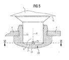
- eine vergrößerte Schnittdarstellung des Lagerbereiches eines Verriegelungsschenkels entsprechend der Schnittlinie V-V in Fig. 1.
- Fig. 6
- eine Schnittdarstellung entsprechend der Schnittlinie VI-VI in Fig. 5 bzw. eine vergrößerte Frontansicht des Bereiches VI in Fig. 1.
- Fig. 1
- a side view of the connector with a lower part attached to the upper part and on the one hand (left) in the open position and on the other hand (right) in the locking position befindlichem locking bracket.
- Fig. 2
- a plan view of the opened lower part in the direction of arrow II of Fig. 1st
- Fig. 3
- an enlarged side view of the area III in Fig. 1st
- Fig. 4
- an enlarged plan view of the area IV of FIG. 2.
- Fig. 5
- an enlarged sectional view of the storage area of a locking leg corresponding to the section line VV in Fig. 1st
- Fig. 6
- a sectional view corresponding to the section line VI-VI in Fig. 5 and an enlarged front view of the area VI in Fig. 1st
Der Steckverbinder enthält als Steckverbinderteile das Unterteil 1 und das darauf aufgesteckte Oberteil 2. Die innerhalb der beiden Steckverbinderteile 1,2 angeordneten Kontaktteile sind für die Erfindung ohne Bedeutung und daher nicht dargestellt.The connector contains as connector parts, the
Am Unterteil 1 ist beidseitig je ein Verriegelungsbügel 3 schwenkbar gelagert. Die Verriegelungsbügel 3 weisen jeweils zwei beidseitig an dem Unterteil 1 schwenkbar gelagerte Verriegelungsschenkel 4 auf, die durch ein gemeinsames Griffteil 5 zu dem in Draufsicht U-förmigen, einteiligen Verriegelungsbügel 3 miteinander verbunden sind. Die Schwenkebenen der Verriegelungsschenkel 4 liegen etwa parallel zur in Steckrichtung 6 verlaufenden Mittellängsebene 7 des Steckverbinders. Die Schwenkebenen liegen damit parallel zur Bildebene der Fig. 1,3 und 6 sowie senkrecht zur Bildebene der Fig. 2,4 und 5.On the
Die nach Art einarmiger Hebel wirksamen Verriegelungsschenkel 4 sind jeweils um mit dem Unterteil 1 fest verbundene Schwenkachsen 8 schwenkbar gelagert. Die Schwenkachsen 8 sind durch Achsstummel 9 gebildet, die beidseitig aus den Flanken 10 des Unterteils 1 hinausstehen. Die Verriegelungsschenkel 4 sind mit ihrem inneren Ende schwenkbar auf den Achsstummeln bzw. Lagerzapfen 9 des Unterteils 1 gelagert. Das eine Lagerende 11 und das andere Verriegelungsende 12 sind die freien Enden der Schenkel einer Winkelform mit dem Winkelscheitel (Seitenansicht in Fig. 1 und 3) als Griffteil 5. Diese Winkelform kann auch als V-Form bezeichnet werden. Trotzdem ist jeder Verriegelungsschenkel 4 wirkungsmäßig ein einarmiger Hebel, der durch sein Verriegelungsende 12 mit dem durch einen Verriegelungszapfen 13 gebildeten Verriegelungsvorsprung des Unterteils 1 nach Art eines Vorreibers zusammenwirkt. In Verriegelungsstellung (Fig. 1, rechts und Fig. 3) beaufschlagt der Verriegelungsschenkel 4 mit der inneren Seitenkante 14 seines dem Verriegelungsende 12 zugeordneten V-Schenkels unmittelbar den Umfang des Verriegelungszapfens 13, während er in Öffnungsstellung den Verriegelungszapfen 13 zum unbehinderten Lösen des Oberteils 2 vom Unterteil 1 freigibt (Fig. 1. links).The one-armed lever
Aus der zur Mittellängsebene 7 parallelen Flachebene des Verriegelungsschenkels 4 steht ein mit dem Verriegelungsschenkel 4 einstückiger, aus seiner Flächenerstreckung abgewinkelter Federausleger 15 in Richtung nach innen, d.h. in Verriegelungsstellung in Richtung auf das Oberteil 2 ab. Der Federausleger 15 beaufschlagt in Verriegelungsstellung mit seiner zugewandten Oberfläche den Verriegelungszapfen 13 von oben und bildet dadurch ein Gehemme. Es kann dies ein blattfederartig wirksames Reibgehemme sein. Beim Ausführungsbeispiel ist dies ein Formgehemme dadurch, daß der Federausleger 15 auf seiner dem Verriegelungszapfen 13 zugewandten Seite ausgemuldet ist. Wenn hier der Ausleger als Federausleger 15 bezeichnet ist, so muß das nicht bedeuten, daß er in Raststellung zusätzlich eine Federwirkung auf den Verriegelungszapfen 13 ausüben muß. Im Hinblick auf seine durch die Ausmuldung 16 in Verriegelungsstellung gebildete Formschlußwirkung ist in entsprechender Schwenkstellung des Verriegelungsschenkels 4 bzw. des Verriegelungsbügels 3 ein Formschluß gegenüber dem Verriegelungszapfen 13 vorhanden, welcher Ursache für die Gehemmewirkung ist. Nur bei einer mit entsprechendem Kraftaufwand möglichen Rückschwenkung des Verriegelungsbügels 3 bzw. seiner Verriegelungsschenkel 4 aus der Verriegelungsstellung (Fig. 1, rechts) in die Öffnungsstellung (Fig. 1, links) bedarf es einer gewissen Federeigenschaft des Auslegers 15 gegenüber den Verriegelungsschenkeln 4, um die gewünschte Gehemmefunktion zu erfüllen.From the plane parallel to the central longitudinal plane 7 plane of the locking
Der Federausleger 15 ist durch einen in Richtung der Schwenkachse 8 von seinem Halteende 18 nach innen abgehenden Verbindungssteg 17 mit dem Verriegelungsschenkel 4 einstückig verbunden und zwar im Bereich von dessen Verriegelungsende 12. Von dem Halteende 18 im Bereich des Verbindungssteges 17 steht der Ausleger 15 in Richtung etwa parallel zur Flächenerstreckung des Verriegelungsschenkels 4 ab, und zwar entgegen der Hintergriffrichtung 19. Auf die Steckverbinderteile 1,2 wirkende Zugkräfte werden nicht über den Federausleger 15, sondern über die Unter- oder Seitenkante 14 des Verriegelungsschenkels 4 - und über den zapfenförmigen Verriegelungsvorsprung 13 - in den jeweiligen Verriegelungsbügel 3 eingeleitet.The
In mindestens der Entriegelungsstellung des Verriegelungsbügels 3 bzw. seiner Verriegelungsschenkel 4 ist ein dessen Schwenkbeweglichkeit gegenüber dem schwenklagernden Unterteil 1 hemmendes Rastgehemme wirksam. Die Wirksamkeit erstreckt sich auf den Lagerbereich zwischen dem Verriegelungsschenkel 4 und dem ihn lagernden Lagerzapfen 9 des Unterteils 1. In den Verriegelungsschenkel 4 ist drehfest eine Lagerhülse 20 eingesetzt. Die Lagerhülse 20 überdeckt die Stirnfläche 21 des Lagerzapfens bzw. Achsstummels 9 mit ihrer Kappe 22. Sie umgibt den Mantel des Achsstummels 9 mit ihrem inneren Zylindermantel 23. Das Rastgehemme ist zwischen der Kappe 22 und dem Stirnende 21 des Lagerzapfens 9 wirksam. Die Lagerhülse 20 ist durch ein Kunststoffteil gebildet, welches durch eine Formschlußverrastung 24 mit dem Verriegelungsschenkel 4 drehfest verbunden ist.In at least the unlocking position of the
Aus der Verschlußkappe 22 steht in Richtung auf das Stirnende 21 des Lagerzapfens 9 ein Rastvorsprung in Form einer Längsrippe 25 vor. Die Längsrippe 24 erstreckt sich im wesentlichen radial zweckmäßig über den gesamten Durchmesser des Lagerzapfens 9. Sie weist die Querschnittsform eines Keiles auf, dessen Flanken in Richtung auf den Lagerzapfen 9 konvergieren und damit Auflaufschrägen bilden. Der Kunststoffwerkstoff der Verschlußkappen 22 ist von einer Federelastizität, die für die Erzeugung eines ausreichenden, in Richtung auf die Stirnfläche 21 des Lagerzapfens 9 orientierten Federdruckes ausreicht. Diese Federwirkung dient zum Eingriff der Längsrippe 25 in eine sich über die Stirnfläche 21 erstreckende Rastkerbe 26, wenn sich der Verriegelungsschenkel 4 in einer solchen Drehstellung auf dem Achsstummel 9 befindet, daß die Längsrippe 25 in winkelmäßiger Überdeckung mit der Rastkerbe 26 steht. Die Rastkerbe 26 erstreckt sich zweckmäßigerweise über den gesamten Durchmesser des Lagerzapfens 9. Ihre Winkelstellung ist so gewählt, daß sie in Öffnungsstellung des Verriegelungsbügels 3 mit der Winkelstellung der Längsrippe 25 korrespondiert. Beim Ausführungsbeispiel ist eine zweite Rastkerbe 27 auf der Stirnfläche 21 des Lagerzapfens 9 in einer anderen Winkelstellung angeordnet, die der Verriegelungsstellung des Verriegelungsbügels 3 bzw. der Verriegelungsschenkel 4 zugeordnet ist. Die Rastkerbe 27 sorgt dadurch in Verriegelungsstellung gemeinsam mit der Längsrippe 25 für eine zweite Rasthemmung zusätzlich zum durch das Zusammenwirken des Federauslegers 15 mit dem Verriegelungszapfen 13 gebildeten Rastgehemme.From the
Die Verriegelungszapfen 13 am Oberteil 2 und die Lagerzapfen 9 am Unterteil 1 sind vorzugsweise hinsichtlich Form und Anordnung identisch. Dadurch kann der Verriegelungsbügel 3 wahlweise auch am Oberteil 2 gelagert werden. Dann ist der Lagerzapfen 9 am Unterteil 1 als Verriegelungszapfen für den Verriegelungsbügel 3 wirksam.The locking
- 11
- Unterteillower part
- 22
- Oberteiltop
- 33
- Verriegelungsbügellocking clip
- 44
- Verriegelungsschenkellocking leg
- 55
- Griffteilhandle part
- 66
- Steckrichtungplug-in direction
- 77
- MittellängsebeneCentral longitudinal plane
- 88th
- Schwenkachseswivel axis
- 99
- Achsstummel, LagerzapfenStub axle, bearing pin
- 1010
- Flankeflank
- 1111
- Lagerendebearing end
- 1212
- Verriegelungsendelocking end
- 1313
- Verriegelungszapfenlocking pin
- 1414
- innere Seitenkanteinner side edge
- 1515
- Federauslegerspring boom
- 1616
- AusmuldungAusmuldung
- 1717
- Verbindungsstegconnecting web
- 1818
- Halteendeholding end
- 1919
- HintergriffrichtungRear engagement direction
- 2020
- Lagerhülsebearing sleeve
- 2121
- Stirnflächeface
- 2222
- Kappecap
- 2323
- Zylindermantelcylinder surface
- 2424
- FormschlußverrastungFormschlußverrastung
- 2525
- Längsrippelongitudinal rib
- 2626
- Rastkerbenotch
- 2727
- Rastkerbenotch
Claims (14)
- Electrical plug connector having a lower part (1) and an upper part (2), which can be plugged onto said lower part (1), as plug connector parts,- at least one locking clip (3) being mounted on a plug connector part (1) such that it can pivot, said locking clip (3) having two locking limbs (4), which can be locked to the other plug connector part (2) and are connected to one another by means of a common grip part (5),- the locking limbs (4), which are formed by approximately mutually parallel flat parts, engaging with their unmounted locking ends (12) behind in each case one locking projection (13), which is provided on the other plug connector part (2) and extends transversely with respect to the insertion direction (6), and being secured in the engaged-behind position by means of spring pressure, and- a side edge (14) of the locking limbs (4) acting directly on the respective locking projection (13),characterized in that a spring extension arm (15), which is integral with the locking limb (4), is bent back from its flat extent and engages around the locking projection (13) in the locked position, is provided for the purpose of producing the spring pressure.
- Plug connector according to Claim 1, characterized in that the spring extension arm (15) is hollowed out (16).
- Plug connector according to Claim 2, characterized by a radius of the hollowed-out section (16) which approximately corresponds to half the diameter of the locking projection (13).
- Plug connector according to one or more of the preceding claims, characterized in that a connecting web (17) between a locking limb (4) and its spring extension arm (15) is connected only to one holding end (18) of the extension arm (15), from which holding end (18) the spring extension arm (15) protrudes in the direction which is approximately parallel to the flat extent of the locking limb (4).
- Plug connector according to Claim 4, characterized in that the spring extension arm (15) protrudes from the connecting web (17) in the opposite direction to the engage-behind direction (19) of its locking limb (4).
- Plug connector according to one or more of the preceding claims, characterized by intrinsic material resilience at least of the spring extension arm (15) of the locking limbs (4).
- Plug connector according to one or more of the preceding claims, characterized in that, at least in the unlocked position of a locking clip (3), a latching inhibitor acts which inhibits the ability of the locking clip (3) to pivot with respect to the plug connector part (1) on which it is mounted such that it can pivot.
- Plug connector according to Claim 7, characterized in that latching inhibition acts at each of the ends of the pivot region of the locking clip in its unlocked and/or locked position.
- Plug connector according to Claim 7 or 8, characterized in that the latching inhibitor acts between the bearing region of at least one locking limb (4) and one bearing journal (9), which bears said locking limb (4), on a plug connector part (1).
- Plug connector according to one of Claims 7 to 9, characterized by a bearing sleeve (20), which is inserted in a locking limb (4), is placed on a bearing journal (9) of a plug connector part (1) and is closed at its end which is remote from the associated plug connector part (1) by a cover (22) in the form of a closure cap, the latching inhibitor acting between the closure cap (22) and the front end (21) of the bearing journal (9).
- Plug connector according to Claim 10, characterized in that the bearing sleeve (20) is formed by a plastic part.
- Plug connector according to Claim 11, characterized by a latching projection (25), which protrudes out of the closure cap (22) in the direction of the front end (21) of the bearing journal and engages in a resilient manner in a latching recess in the front end of the bearing journal (9) for latching inhibition purposes.
- Plug connector according to Claim 12, characterized in that the latching projection of the closure cap (22) is formed by a radially aligned longitudinal rib (25) which corresponds to a radial slot (26) in the front end (21) of the bearing journal (9) for latching inhibition purposes.
- Plug connector according to one or more of the preceding claims, characterized in that the locking projections (13) and the bearing journals (9) are identical as regards their design and arrangement on the plug connector parts (1, 2), such that the locking clip (3) may also optionally be mounted on the locking projection (13), the bearing journal (9) in this case taking on the function of a locking projection.
Applications Claiming Priority (2)
| Application Number | Priority Date | Filing Date | Title |
|---|---|---|---|
| DE1998130182 DE19830182A1 (en) | 1998-07-06 | 1998-07-06 | Electrical connector |
| DE19830182 | 1998-07-06 |
Publications (3)
| Publication Number | Publication Date |
|---|---|
| EP0971455A2 EP0971455A2 (en) | 2000-01-12 |
| EP0971455A3 EP0971455A3 (en) | 2000-11-02 |
| EP0971455B1 true EP0971455B1 (en) | 2005-09-21 |
Family
ID=7873145
Family Applications (1)
| Application Number | Title | Priority Date | Filing Date |
|---|---|---|---|
| EP19990112519 Expired - Lifetime EP0971455B1 (en) | 1998-07-06 | 1999-07-01 | Electrical connector |
Country Status (2)
| Country | Link |
|---|---|
| EP (1) | EP0971455B1 (en) |
| DE (2) | DE19830182A1 (en) |
Families Citing this family (8)
| Publication number | Priority date | Publication date | Assignee | Title |
|---|---|---|---|---|
| DE10120846A1 (en) * | 2001-04-27 | 2002-11-28 | Wieland Electric Gmbh | Electrical connector |
| DE10216796A1 (en) * | 2002-03-06 | 2003-12-24 | Wieland Electric Gmbh | Electrical connector |
| DE202005005241U1 (en) * | 2004-07-30 | 2005-12-08 | Weidmüller Interface GmbH & Co. KG | Heavy electrical connector with locking clips |
| DE202009011625U1 (en) | 2009-08-28 | 2011-01-13 | Wieland Electric Gmbh | Connectors, in particular industrial connectors |
| DE102012015737A1 (en) | 2012-08-09 | 2014-02-13 | Amphenol-Tuchel Electronics Gmbh | Industrial plug connector used in agricultural machinery, has contact element that is extended into receiving space and is protruded on outer surface of housing, and shock absorber that is arranged adjacent to plug-side face of housing |
| DE102017119057B3 (en) | 2017-08-21 | 2018-11-08 | Harting Electric Gmbh & Co. Kg | System of two connector housings and a locking device |
| DE102019108629A1 (en) * | 2019-03-27 | 2020-10-01 | Harting Electric Gmbh & Co. Kg | Connector housing |
| CN116581608B (en) * | 2023-07-12 | 2023-09-12 | 海的电子科技(苏州)有限公司 | Power connector assembly and display panel aging test furnace |
Family Cites Families (6)
| Publication number | Priority date | Publication date | Assignee | Title |
|---|---|---|---|---|
| DE8908016U1 (en) * | 1989-06-30 | 1989-08-31 | Hts-Elektrotechnik Gmbh, 5206 Neunkirchen-Seelscheid, De | |
| DE4207565C1 (en) * | 1992-03-10 | 1992-12-24 | Weidmueller Interface Gmbh & Co, 4930 Detmold, De | Releasable arrester for plug connectors, cable tension relief or similar - has deformable arresting spring strip in jaw region of pivotable arresting hook and pin |
| DE9216693U1 (en) * | 1992-12-08 | 1994-04-07 | Framatome Connectors Int | Electrical connector |
| DE4241256C2 (en) * | 1992-12-08 | 2001-08-16 | Framatome Connectors Int | Electrical connector |
| DE19508605C1 (en) * | 1995-03-10 | 1996-07-11 | Harting Elektronik Gmbh | Electrical plug-in connection |
| DE19633827C1 (en) * | 1996-08-22 | 1997-11-20 | Contact Gmbh | Locking yoke for plug-in connection device |
-
1998
- 1998-07-06 DE DE1998130182 patent/DE19830182A1/en not_active Ceased
-
1999
- 1999-07-01 EP EP19990112519 patent/EP0971455B1/en not_active Expired - Lifetime
- 1999-07-01 DE DE59912570T patent/DE59912570D1/en not_active Expired - Fee Related
Also Published As
| Publication number | Publication date |
|---|---|
| EP0971455A3 (en) | 2000-11-02 |
| DE19830182A1 (en) | 2000-01-20 |
| EP0971455A2 (en) | 2000-01-12 |
| DE59912570D1 (en) | 2005-10-27 |
Similar Documents
| Publication | Publication Date | Title |
|---|---|---|
| EP2133959B1 (en) | Locking device for plug connector housings | |
| DE4034216C1 (en) | ||
| DE102017121868B3 (en) | Locking bar with lock and a method for locking and unlocking a connector | |
| EP0971455B1 (en) | Electrical connector | |
| EP0471989B1 (en) | Pipe clamp | |
| DE3433106A1 (en) | Wiper arm, in particular for wiper systems on motor vehicles | |
| EP0567821B1 (en) | Pipe clamp | |
| EP3776750A1 (en) | Electrical plug-in connector part and electrical plug-in connection system with locking | |
| EP1604432A1 (en) | Securing element for preventing the opening of a plug connection between a cable harness plug and a coupler plug | |
| DE4000517A1 (en) | Lock housing sheet metal cupboard door etc. - is inserted in door round aperture and has surface with notches as axial grooves | |
| DE102012011660A1 (en) | Wiper blade, wiper arm and connection arrangement for a windshield wiper system of a vehicle | |
| DE69916122T2 (en) | CYLINDER LOCK | |
| DE10202344B4 (en) | Closure consisting of closing part and counter-closing part | |
| EP2043199A1 (en) | Connector | |
| EP1732175B1 (en) | Angular connector housing with cover | |
| EP1801485B1 (en) | Coupling device for interconnecting multiple fluid lines | |
| EP1018589A1 (en) | Tolerance-compensation for a power transmitting connection between a handle and a lock trigger | |
| DE1904310U (en) | HOSE COUPLING. | |
| EP0673085A2 (en) | Device for locking a connector housing | |
| DE8531316U1 (en) | Vehicle mirror | |
| DE10006433A1 (en) | Locking clasp for plug connector | |
| EP1934492A1 (en) | Holder for a rod | |
| DE10346088B4 (en) | Holder for a fuel line | |
| DE2410413C2 (en) | Latch bolt lock | |
| AT403617B (en) | CONNECTING FITTING FOR DETACHABLE CONNECTION OF TWO FURNITURE PARTS |
Legal Events
| Date | Code | Title | Description |
|---|---|---|---|
| PUAI | Public reference made under article 153(3) epc to a published international application that has entered the european phase |
Free format text: ORIGINAL CODE: 0009012 |
|
| AK | Designated contracting states |
Kind code of ref document: A2 Designated state(s): DE FR GB IT NL SE |
|
| AX | Request for extension of the european patent |
Free format text: AL;LT;LV;MK;RO;SI |
|
| PUAL | Search report despatched |
Free format text: ORIGINAL CODE: 0009013 |
|
| AK | Designated contracting states |
Kind code of ref document: A3 Designated state(s): AT BE CH CY DE DK ES FI FR GB GR IE IT LI LU MC NL PT SE |
|
| AX | Request for extension of the european patent |
Free format text: AL;LT;LV;MK;RO;SI |
|
| 17P | Request for examination filed |
Effective date: 20001202 |
|
| AKX | Designation fees paid |
Free format text: DE FR GB IT NL SE |
|
| GRAP | Despatch of communication of intention to grant a patent |
Free format text: ORIGINAL CODE: EPIDOSNIGR1 |
|
| GRAS | Grant fee paid |
Free format text: ORIGINAL CODE: EPIDOSNIGR3 |
|
| GRAA | (expected) grant |
Free format text: ORIGINAL CODE: 0009210 |
|
| AK | Designated contracting states |
Kind code of ref document: B1 Designated state(s): DE FR GB IT NL SE |
|
| REG | Reference to a national code |
Ref country code: GB Ref legal event code: FG4D Free format text: NOT ENGLISH |
|
| REF | Corresponds to: |
Ref document number: 59912570 Country of ref document: DE Date of ref document: 20051027 Kind code of ref document: P |
|
| GBT | Gb: translation of ep patent filed (gb section 77(6)(a)/1977) |
Effective date: 20051213 |
|
| REG | Reference to a national code |
Ref country code: SE Ref legal event code: TRGR |
|
| ET | Fr: translation filed | ||
| PGFP | Annual fee paid to national office [announced via postgrant information from national office to epo] |
Ref country code: NL Payment date: 20060718 Year of fee payment: 8 |
|
| PGFP | Annual fee paid to national office [announced via postgrant information from national office to epo] |
Ref country code: FR Payment date: 20060719 Year of fee payment: 8 |
|
| PGFP | Annual fee paid to national office [announced via postgrant information from national office to epo] |
Ref country code: GB Payment date: 20060721 Year of fee payment: 8 |
|
| PLBE | No opposition filed within time limit |
Free format text: ORIGINAL CODE: 0009261 |
|
| STAA | Information on the status of an ep patent application or granted ep patent |
Free format text: STATUS: NO OPPOSITION FILED WITHIN TIME LIMIT |
|
| PGFP | Annual fee paid to national office [announced via postgrant information from national office to epo] |
Ref country code: IT Payment date: 20060731 Year of fee payment: 8 |
|
| 26N | No opposition filed |
Effective date: 20060622 |
|
| PGFP | Annual fee paid to national office [announced via postgrant information from national office to epo] |
Ref country code: SE Payment date: 20060724 Year of fee payment: 8 |
|
| EUG | Se: european patent has lapsed | ||
| GBPC | Gb: european patent ceased through non-payment of renewal fee |
Effective date: 20070701 |
|
| NLV4 | Nl: lapsed or anulled due to non-payment of the annual fee |
Effective date: 20080201 |
|
| PG25 | Lapsed in a contracting state [announced via postgrant information from national office to epo] |
Ref country code: SE Free format text: LAPSE BECAUSE OF NON-PAYMENT OF DUE FEES Effective date: 20070702 Ref country code: NL Free format text: LAPSE BECAUSE OF NON-PAYMENT OF DUE FEES Effective date: 20080201 |
|
| PG25 | Lapsed in a contracting state [announced via postgrant information from national office to epo] |
Ref country code: GB Free format text: LAPSE BECAUSE OF NON-PAYMENT OF DUE FEES Effective date: 20070701 |
|
| REG | Reference to a national code |
Ref country code: FR Ref legal event code: ST Effective date: 20080331 |
|
| PG25 | Lapsed in a contracting state [announced via postgrant information from national office to epo] |
Ref country code: FR Free format text: LAPSE BECAUSE OF NON-PAYMENT OF DUE FEES Effective date: 20070731 |
|
| PGFP | Annual fee paid to national office [announced via postgrant information from national office to epo] |
Ref country code: DE Payment date: 20080731 Year of fee payment: 10 |
|
| PG25 | Lapsed in a contracting state [announced via postgrant information from national office to epo] |
Ref country code: IT Free format text: LAPSE BECAUSE OF NON-PAYMENT OF DUE FEES Effective date: 20070701 |
|
| PG25 | Lapsed in a contracting state [announced via postgrant information from national office to epo] |
Ref country code: DE Free format text: LAPSE BECAUSE OF NON-PAYMENT OF DUE FEES Effective date: 20100202 |