EP0971407B1 - Thermal conductive unit and thermal connection structure using same - Google Patents
Thermal conductive unit and thermal connection structure using same Download PDFInfo
- Publication number
- EP0971407B1 EP0971407B1 EP98947805A EP98947805A EP0971407B1 EP 0971407 B1 EP0971407 B1 EP 0971407B1 EP 98947805 A EP98947805 A EP 98947805A EP 98947805 A EP98947805 A EP 98947805A EP 0971407 B1 EP0971407 B1 EP 0971407B1
- Authority
- EP
- European Patent Office
- Prior art keywords
- heat
- heat conducting
- conducting unit
- graphite
- sheet
- Prior art date
- Legal status (The legal status is an assumption and is not a legal conclusion. Google has not performed a legal analysis and makes no representation as to the accuracy of the status listed.)
- Expired - Lifetime
Links
Images


Classifications
-
- F—MECHANICAL ENGINEERING; LIGHTING; HEATING; WEAPONS; BLASTING
- F28—HEAT EXCHANGE IN GENERAL
- F28F—DETAILS OF HEAT-EXCHANGE AND HEAT-TRANSFER APPARATUS, OF GENERAL APPLICATION
- F28F13/00—Arrangements for modifying heat-transfer, e.g. increasing, decreasing
-
- F—MECHANICAL ENGINEERING; LIGHTING; HEATING; WEAPONS; BLASTING
- F28—HEAT EXCHANGE IN GENERAL
- F28F—DETAILS OF HEAT-EXCHANGE AND HEAT-TRANSFER APPARATUS, OF GENERAL APPLICATION
- F28F21/00—Constructions of heat-exchange apparatus characterised by the selection of particular materials
- F28F21/02—Constructions of heat-exchange apparatus characterised by the selection of particular materials of carbon, e.g. graphite
-
- H—ELECTRICITY
- H01—ELECTRIC ELEMENTS
- H01L—SEMICONDUCTOR DEVICES NOT COVERED BY CLASS H10
- H01L23/00—Details of semiconductor or other solid state devices
- H01L23/34—Arrangements for cooling, heating, ventilating or temperature compensation ; Temperature sensing arrangements
- H01L23/36—Selection of materials, or shaping, to facilitate cooling or heating, e.g. heatsinks
- H01L23/367—Cooling facilitated by shape of device
- H01L23/3672—Foil-like cooling fins or heat sinks
-
- H—ELECTRICITY
- H01—ELECTRIC ELEMENTS
- H01L—SEMICONDUCTOR DEVICES NOT COVERED BY CLASS H10
- H01L23/00—Details of semiconductor or other solid state devices
- H01L23/34—Arrangements for cooling, heating, ventilating or temperature compensation ; Temperature sensing arrangements
- H01L23/40—Mountings or securing means for detachable cooling or heating arrangements ; fixed by friction, plugs or springs
- H01L23/4006—Mountings or securing means for detachable cooling or heating arrangements ; fixed by friction, plugs or springs with bolts or screws
-
- H—ELECTRICITY
- H01—ELECTRIC ELEMENTS
- H01L—SEMICONDUCTOR DEVICES NOT COVERED BY CLASS H10
- H01L2924/00—Indexing scheme for arrangements or methods for connecting or disconnecting semiconductor or solid-state bodies as covered by H01L24/00
- H01L2924/0001—Technical content checked by a classifier
- H01L2924/0002—Not covered by any one of groups H01L24/00, H01L24/00 and H01L2224/00
Definitions
- the present invention relates to heat conducting units designed to remove internally generated heat from electronic equipments which are very highly integrated for size and weight reduction, such as notebook-sized personal computers, portable information terminals; a heat path is formed by connecting parts at different temperatures in an electronic device so that heat generated in a hotter part can be efficiently transferred to a cooler part. More specifically, the present invention relates to a heat conducting unit for instantaneously transferring heat generated in a part at high temperature so that the heat will not be conducted around, and a heat connecting structure using the heat conducting unit.
- air cooling system is widely adopted to cool electronic components, in which a fan is installed inside an electronic device to produce internal air flow to transfer heat generated in a higher-temperature part to a lower-temperature part or to remove heat to outside.
- a radiation board made of aluminum is bonded to the CPU with a highly heat conducting adhesive, or a radiation board is pressed against the CPU over a radiation sheet made of a conducting material such as silicone polymer, so as to conduct the heat from the CPU to the radiation board where it is dissipated.
- the metal plate of aluminum on the back of the key board is used for a radiation board and the heat is dissipated from the metal plate through a radiation sheet made of silicone polymer.
- the heat dissipating capability of the radiation board when dissipating heat from a radiation board by thermal conduction, the heat dissipating capability of the radiation board must be increased depending on how much heat would be dissipated. Generally, increasing the heat dissipating capability requires a larger heat dissipating area of the radiation board. However, in most cases, electronic components are fixed in predetermined positions, and therefore the radiation board will interfere with the electronic components if it is simply enlarged to ensure the dissipating area. Then the radiation board must be formed in complicated shape to avoid interference with the electronic components. Further, in many cases, one unit of radiation board has to be made of two or more radiation parts when it cannot be made of a single radiation part.
- two radiation parts forming a radiation board are provided, as an integrated radiation board, with a radiation sheet made of silicone polymer etc. interposed between them, or with screws fastening the two radiation parts.
- some of the radiation parts may provide lower thermal conductivity, or connective thermal resistance may be developed between the radiation parts, and then the heat resistance of the entire heat dissipating path increases to decrease the heat dissipating capability. If a larger radiation board is used to solve these problems, this will cause a vicious circle of increasing the weight of the electronic equipment.
- the heat resistance of the entire heat dissipating path is increased, then the heat generated in the heat generating part will be conducted to the surrounding electronic components before dissipated through the heat dissipating path and will exert thermal effects on the electronic components.
- a radiation board made of metal like copper having superior thermal conductivity to aluminum is heavier. Even for an aluminum radiation board, its weight cannot be neglected from the viewpoint of size and weight reduction. In portable information processors, etc., lighter heat conducting units with efficient heat conductivity are demanded so as to reduce size and weight of main devices.
- the heat conducting unit TCU1 of this embodiment has a container C extending in one direction to form an approximately rectangular space As inside and rim sections 20A, 20B, 20C and 20D integrally extending approximately in the center of the side wall of the container C.
- the rim section 20A and the rim section 20B are formed on the opposite sides perpendicular to the elongate direction of the container C and the rim section 20C and the rim section 20D are formed on the opposite sides parallel to the elongate direction of the container C.
- the container C has a first case Cb and a second case Ct.
- a recessed part Asb is formed in the first case Cb configured in a square pillar shape by four side walls 18Ab, 18Bb, 18Cb, and 18Db substantially perpendicular to each other, and is closed open end thereof by a bottom wall 18Eb.
- the rims 20Ab, 20Bb, 20Cb and 20Db extend in a given length L from the edge of the opening of the first case Cb approximately in parallel with the bottom wall 18Eb.
- the side walls 18Ab, 18Cb, 18Cb, 18Db, the bottom wall 18Eb, and the rims 20Ab, 20Bb, 20Cb, 20Db are made of a sheet material composed of a high-molecular compound having a given thickness Ts.
- the second case Ct is in substantially the same shape as the first case Cb. That is to say, a recessed part Ast is formed in the second case Ct configured in a square pillar shape by four side walls 18At, 18Bt, 18Ct, and 18Dt substantially perpendicular to each other, and is closed one open end thereof by a top wall 18Et.
- the rims 20At, 20Bt, 20Ct and 20Dt extend in a given length L from the edge of the opening of the second case Ct approximately in parallel with the bottom wall 18Eb.
- the side walls 18At, 18Bt, 18Ct, 18Dt, the bottom wall 18Et, and the rims 20At, 20Bt, 20Ct, 20Dt are made of a sheet material composed of polyester having a thickness of 20 to 30 ⁇ m.
- the first and second cases thus constructed are arranged with their respective openings facing to each other, and the opposing rims 20Ab and 20At, 20Bb and 20Bt, 20Cb and 20Ct, and 20Db and 20Dt are joined together to form the container C having the space As formed of the recessed part Asb and the recessed part Ast.
- the rims 20Ab and 20At, 20Bb and 20Bt, 20Cb and 20Ct, and 20Db and 20Dt are joined together to form the rim sections 20A, 20B, 20C and 20D.
- the rim section 20 may be joined with an adhesive agent, or may be thermally welded when the high-molecular compound sheet material has thermoplasticity.
- the formation of the rim section 20 around the container C prevents direct application of force to the container C from around, and also strengthen the entirety of the heat conducting unit TCU.
- Fig.1C shows the section IC-IC of the heat conducting unit TCU1 shown in Fig.1A.
- a graphite sheet group GS including a given number of stacked flexible graphite sheets 1 is contained in the space As of the container C.
- all of the graphite sheets 1 forming the graphite sheet group GS are substantially in the same shape.
- using the graphite sheets 1 formed in different shapes is also effective depending on the application of the heat conducting unit TCU1.
- Fig.1D shows an example of the graphite sheet group GS composed of graphite sheets 1 having different lengths.
- the graphite sheets 1 each differing in length by ⁇ SL are stacked in order, to form the graphite sheet group GS.
- a heat conducting unit TCU1 containing such a graphite sheet group GS composed of graphite sheets 1 of different lengths is suitable when the heat conducting unit TCU1 is used in a form bent in one direction, in which the difference in length, ⁇ SL, between the graphite sheets 1 can appropriately be determined in accordance with the thickness Tg of each graphite sheet 1, the number of the graphite sheets 1 forming the graphite sheet group GS, the thickness Ts of the high-molecular compound sheet of the container C, and the curvature of the bend of the heat conducting unit TCU.
- Such heat conducting units TCU1 formed by bending graphite sheets 1 will be described later referring to Fig. 4A, Fig. 4B, Fig. 4C and Fig. 5A, Fig.5B, Fig.5C.
- a graphite sheet group GS containing graphite sheets 1 having excellent thermal conductivity but easy to break because of its inferior peeling strength is contained in a container C composed of a protect sheet of polyester, which protects the graphite sheet group GS from stresses and impact force exerted from outside; the entire heat conducting unit TCU1 ensures strength enough to endure actual use for the graphite sheets 1 and the graphite sheet group GS.
- the graphite sheets 1 and the polyester of the container C must satisfy the following conditions to allow the heat conducting unit TCU1 to exert this performance.
- graphite sheets having useful properties such as excellent thermal resistance, chemical resistance are widely used for industrial material for gaskets, heat-resisting seal material
- the graphite sheets 1 of the present invention can be produced by the following methods roughly classified into three groups.
- film of a particular high-molecular compound is heat-treated at a temperature of 2400°C or higher in an inert gas to form graphite structure, which is processed at high temperature to create foam condition and is rolled to produce graphite sheet having flexibility and elasticity (for example, refer to Japanese Patent Laying-Open No.3-75211, Japanese Patent Laying-Open No. 8-23183, Japanese Patent Laying-Open No. 8-267647, and Japanese Patent Laying-Open No.9-156913).
- the graphite sheets obtained by this manufacturing method ones with specific gravity of 0.5 to 2.25 and thermal conductivity of 600 to 1,004 W/mk are suitable as the graphite sheets 1 of the present invention.
- the range of the specific gravity is set large because of differences among manufacturing methods; sheet materials with good flexibility have smaller specific gravity (0.5 to 1.5) and sheet materials with poor flexibility have larger specific gravity (1.5 to 2.3).
- the graphite sheets 1 While the graphite sheets 1 have high thermal conductivity and excellent heat transferring property, the graphite sheets 1 need to have large cross-sectional sections to sufficiently conduct heat. For this, the thickness Tg of the graphite sheets 1 should be set large. However, if the thickness Tg of the graphite sheet is too large, then the graphite sheet will become very weak because of a reason in production, and it cannot provide sufficient flexibility. Accordingly the thickness Tg of the graphite sheet 1 is preferably not smaller than 10 ⁇ m nor larger than 800 ⁇ m.
- the graphite sheets 1 used in the first embodiment have a thickness Ts of 100 ⁇ m, thermal conductivity of 600 to 1004 W/mk, and a specific gravity of 0.8 to 1.0.
- natural graphite is treated with acid like sulfuric acid or nitric acid and then heated to obtain expanded graphite, and then it is roll-formed to obtain an expanded graphite sheet. While this expanded graphite sheet has flexibility and can be used for gaskets etc., its thermal conductivity is about 1/10 as compared with the graphite sheet obtained in the first manufacturing method, but it has the advantage of very low manufacture cost.
- a third manufacturing method obtains a thin film of carbon formed by physical or chemical manufacturing technique such as a Union Carbide System, a Vacuum Deposition Method, a CVD (Chemical Deposition) Method, a Sputtering Method, an Ion Plating Method.
- the thin film of carbon thus obtained is characterized by its relatively high thermal conductivity.
- a graphite sheet or a carbon film formed by methods similar to the first method may be used.
- graphite sheets manufactured by the first method are preferred, but, generally, ones with thermal conductivity of 100 W/mk or higher and specific gravity of 2.0 or smaller can be used as the graphite sheet 1 without practical problems.
- the graphite sheets 1 When forming the graphite sheet group GS by stacking a plurality of graphite sheets 1 thus prepared, the graphite sheets 1 may be bonded to each other to fix the shape of the graphite sheet group GS.
- Adhesives such as epoxy adhesives, acrylate adhesives, or silicone adhesives may be used to bond the graphite sheets 1 to fix the shape of the graphite sheet group GS. Needless to say, adhesives with higher thermal conductivity are preferred.
- the high-molecular compound sheet forming the container C and the rim section 20 of the heat conducting unit TCU1 is required to provide insulating property, chemical resistance, and weather resistance, since it is used in an electronic apparatus. Considering these conditions, the material of the high-molecular compound sheet is polyester.
- the high-molecular compound sheet protects the graphite sheet group GS or graphite block GB accommodated in the container C, it is important that the high-molecular compound sheet should not interfere with conduction of heat from a heat generating part to which the graphite sheet group GS or the graphite block GB is connected.
- the high-molecular compound must satisfy both the contradicting requirements of mechanical strength and good thermal conductivity. That is to say, while mechanical strength of the high-molecular compound sheet can be ensured by enlarging the thickness Ts, it deteriorates thermal conductivity.
- the thickness Ts is preferably set as thin as possible on condition that the high-molecular compound sheet provides a tensile strength of 2kg/mm 2 or higher and a shearing strength of 2kg/mm 2 or higher as mechanical strength.
- Polyester with a thickness Ts of 20 to 30 micron is used in this invention.
- the graphite sheet group GS or graphite block GB is not bonded to the high-molecular compound sheet (the container C2). However, they may be bonded together, which is effective to fix shape of the graphite sheet group GS.
- the graphite sheet group GS or graphite block GB accommodated in the heat conducting unit TCU1 is not exposed from the container C.
- a hole of a given size may be formed in the bottom wall 18Eb or top wall 18Et of the container C so that the graphite sheet group GS or graphite block GB can be in direct contact with a higher-temperature part, so as to ensure thermal conductivity of the entire heat conducting unit TCU1.
- Figs.1A, 1C, and 1D show the heat conducting unit TCU1 in a linear form
- the graphite sheets 1, the container C, and the rim section 20 are all flexible. Accordingly the heat conducting unit TCU1 of the present invention can freely be placed in an electronic apparatus. Further, graphite sheets 1 may be previously transformed to fit the shape of the space in which the heat conducting unit TCU1 is installed and then bonded to each other, which can be used as a thermal conducting unit TCU1 having the graphite sheet group GS with its entire shape fixed.
- the heat conducting unit TCU1 of the first embodiment of the present invention is characterized by covering a thing composed by stacking a sheet, or two or more sheet-like graphite, of graphite with a sheet-like high-molecular compound, thus providing a heat conducting unit which gives strength to graphite sheets having high thermal conductivity but inferior tensile strength and peeling strength.
- a heat conducting unit is realized to be light in weight, with high thermal conductivity, and convenience in assembly.
- the sheet-like graphite has a thickness Tg not smaller than 10 ⁇ m nor larger than 800 ⁇ m, and also has flexibility to absorb vibration. It can be in direct contact with a heat generator such as a CPU, an HDD. which may be broken by vibration, thus further improving the heat conducting efficiency.
- the thickness Ts of the sheet-like high-molecular compound is set to 1 ⁇ m or larger and 300 ⁇ m or smaller, it is possible to avoid the problem that the thermal conductivity of the entirety of the heat conducting unit is deteriorated due to excessive thermal resistance of the sheet-like high-molecular compound.
- a sheet-like graphite is processed into a given shape and then covered in a sheet-like high-molecular compound along the shape; it can be easily installed in the main device because it is in the given shape.
- a heat conducting unit TCU2 of this embodiment is the same as the heat conducting unit TCU1 of the first embodiment of the present invention described referring to Figs.1A, 1B, 1C and 1D, except that a rim section 20B' is substituted for the rim section 20B. Accordingly, for simplification, the features common to the heat conducting unit TCU1 and this unit are not described again.
- the first case Cb and the second case Ct are integrally formed, with the rim 20B'b and the rim 20B't of the rim section 20B' abutting on their respective edges.
- the heat conducting unit TCU2 can be fabricated by putting a graphite sheet 1, a graphite sheet group GS, or a graphite block GB in the recessed part Asb of the first case Cb or the recessed part Ast of the second case Ct, turning the second case Ct in the direction of the arrow Dr about the rim section 20B' to lay the second case Ct on the first case Cb, and then joining the rim sections 20A, 20B, 20C, and 20D, similarly to that in the first embodiment.
- Fig.2C shows the section IIC-IIC of the heat conducting unit TCU2 shown in Fig.2A.
- a graphite sheet group GS containing a given number of stacked graphite sheets 1 having flexibility and in substantially the same shape is accommodated in the space As of the container C.
- a graphite sheet block GB having equivalent shape may be used in place of the graphite sheet group GS.
- a graphite sheet group GS composed of graphite sheets 1 of different lengths as shown in Fig.1D, or a graphite block GB of equivalent shape may be accommodated in the container C.
- the heat conducting unit TCU2 when fabricating the heat conducting unit TCU2 by putting the graphite sheet 1, the graphite sheet group GS, or the graphite block GB in the container C (the recessed part Asb and the recessed part Ast), the heat conducting unit TCU2 having the first case Cb and the second case Ct integrally prepared as shown in Fig. 3B does not encounter the failure that the fabrication must be stopped because of lack of the first case Cb or the second case Ct.
- the heat conducting unit TCU3 of this embodiment is entirely the same as the heat conducting unit TCU2 of the second embodiment of the present invention which has been described referring to Figs. 2A, 2B and 2C, except that it does not have the rim section 20B of the heat conducting unit TCU2. Accordingly, for simplification, features common to the heat conducting unit TCU2 and this unit will not be described again.
- the first case Cb and the second case Ct have their respective side wall 18Bb and side wall 18Bt integrally formed along the upper edges.
- the heat conducting unit TCU3 can be fabricated by putting the graphite sheet 1, the graphite sheet group GS, or the graphite block GB in the recessed part Asb of the first case Cb and the recessed part Ast of the second case Ct, turning the second case Ct in the direction of the arrow Dr about the joined side of the side wall 18Bb and the side wall 18Bt to lay the second case Ct on the first case Cb, and then joining the rim sections 20A, 20B, 20C, and 20D.
- Fig.3C shows the section IIIC-IIIC of the heat conducting unit TCU3 shown in Fig.3A.
- a graphite sheet group GS in which a given number of graphite sheets 1 having flexibility and of substantially the same shape are stacked is accommodated in the space As of the container C, but a graphite sheet block GB of equivalent shape may be used in place of the graphite sheet group GS.
- a graphite sheet group GS composed of graphite sheets 1 of different lengths as shown in Fig.1D, or a graphite block GB of equivalent shape may be accommodated in the container C.
- the requirements for the graphite and the high-molecular compound sheet are the same as those for the above-described heat conducting unit TCU2.
- the heat conducting unit TCU3 provides the same effects and features as those of the heat conducting units TCU1 and TCU2 of the first and second embodiments.
- the heat conducting unit TCU3 is similar to the heat conducting unit TCU2 in that the first case Cb and the second case Ct are integrally formed, it does not have the rim section (20B) on the side wall 18B, unlike the heat conducting unit TCU1 and heat conducting unit TCU2.
- the side wall 18B can be in close contact with a heat generating part to increase the heat conducting efficiency without being interfered with by the rim section (20B).
- the graphite sheet 1, the graphite sheet group GS, or the graphite block GB accommodated in the container C is set as close to the side wall 18B as possible, as shown in Fig.3C.
- FIG.4A, 4B, 4C, and Figs.5A, 5B, 5C applications of the above-described heat conducting units TCU of the present invention in transformed shapes will be described.
- the heat conducting unit TCU1 is shown by way of example in these diagrams, it is a matter of course that the heat conducting unit TCU2 and the heat conducting unit TCU3 can be used in the same way as the heat conducting unit TCU1.
- FIG. 4A shows the heat conducting unit TCU1 bent in the elongate direction.
- the graphite sheet 1 or the graphite sheet group GS accommodated in the container C of the heat conducting unit TCU1 and the high-molecular compound sheet can be freely bent, since they have flexibility.
- Fig.4B shows the section IVB-IVB of the heat conducting unit TCU1 shown in Fig.4A.
- This diagram shows the interior of the heat conducting unit TCU1 in an example in which the graphite sheets 1 have approximately the same shape as shown in Fig.1C, more specifically, in an example in which they have approximately the same length in the bent direction.
- both edges of the graphite sheets 1 located in outer comer of the bend are positioned more distant from the rim section 20A and the rim section 20B than the graphite sheets 1 located in inner corner of the bend.
- gaps are formed as shown in the diagram between the side walls and the graphite sheet group GS.
- Fig. 4B shows the gaps in an emphasized manner for clear understanding, they are small enough to be negligible in practice. However, when such gaps are undesirable for the shape of electronic equipment in which the heat conducting unit TCU is used, the formation of the gaps can be prevented by forming the graphite sheets 1 of the graphite sheet group GS in such a way that those located in outer corner of the bend are longer, as has been described referring to Fig.lD.
- Fig.4C shows the heat conducting unit TCU1 fabricated by bending a graphite sheet group GS containing graphite sheets 1 differing in lengths to fit the shape of the space of installation and then completely joining the rim section 20.
- the graphite sheets are sized not so that the longest graphite sheet 1 can be accommodated in the container C, as shown in Fig.1D, but so that the shortest graphite sheet 1 has the length as the space As in the container C.
- this embodiment has shown an example in which it is bent once in the elongate direction, it can be bent not only in the elongate direction but also in arbitrary direction; the number of times that it is bent is not limited to once.
- the heat conducting unit TCU may be shaped in arbitrary bag-like shape, instead of the rectangular shape. Needless to say, when it is formed in a bag-like shape, the rim section 20 continuously extends to the top wall 18Et and the bottom wall 18Eb, without the side wall 18.
- the heat conducting unit TCU may be formed only with the rim section 20A, with the three of the four rim sections 20 omitted, for example.
- the container C may be formed as a bag composed of a high-molecular compound sheet, with the rim sections 20 all omitted.
- FIG. 5A shows the heat conducting unit TCU1 bent in the elongate direction.
- Fig. 5B shows the section VB-VB of the heat conducting unit TCU1 shown in Fig.5A.
- Fig. 5C is similar to Fig.5B, it shows an example in which the heat conducting unit TCU is forced into a shape fitting the surrounding space.
- the graphite sheet 1, the graphite sheet group GS, or the graphite block GB accommodated in the container C is set to form smaller gaps with the side walls in Fig.5B and 5C, it may be set so that the gaps become larger as it is bent, as shown in Fig.4B.
- the heat conducting units TCU having the shapes shown in the modifications can be produced mainly by the following three methods:
- the heat conducting unit TCU containing the graphite sheets 1 to graphite sheet group GS can be shaped in accordance with the shape of the space in electronic equipment, which facilitates assembly of the electronic equipment. Further, when the heat conducting unit TCU is processed into desired shape in advance, the electronic equipment can be fabricated easily.
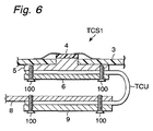
- the heat connecting structure TCS1 of the present invention includes a circuit board 3, a bare chip 4 of CPU of a tape carrier package TCP, a heatsink 5, a flat plate 6, and the heat conducting unit TCU.
- the bare chip 4 of the CPU 4 of TCP is mounted on the circuit board 3, and the circuit board 3 is holed in the part right under the CPU 4.
- the heatsink 5 is bonded directly on the CPU 4, and the heatsink 5 made of aluminum and the flat plate 6 made of aluminum are fastened and fixed with screws 100, with one end of the heat conducting unit TCU of the present invention sandwiched between the heatsink 5 and the flat plate 6.
- a large-area aluminum radiation board 8 and an aluminum flat plate 9 are fastened and fixed with screws 100, with the heat conducting unit TCU sandwiched between the radiation board 8 and the flat plate 9.
- the flat plate 6 and the flat plate 9 are used for the purpose of certainly keeping the heat conducting unit TCU and the heatsink 5, or the heat conducting unit TCU and the radiation board 8 in surface contact; flat plates made of material other than metal, such as resin material, may be used in place of the metal plates.
- a heat conductor having a flat plane such as a metal frame made of a magnesium alloy, may be used in place of the large-area aluminum radiation board 8.
- the heat conducting unit TCU made of a flexible material is pressurized so that the individual graphite sheets, the graphite sheets and the high-molecular compound sheet, and the high-molecular compound sheet and the heat conductors (the heatsink 5, radiation board 8) come in close contact more tightly, to increase the heat conducting efficiency. This is effective especially when the graphite sheets are not bonded to each other, or when the graphite sheets and the high-molecular compound sheet are not bonded.
- the heat conducting unit TCU is fastened with screws to obtain closer contact in this example, it may be pressed with springs, elastic material to obtain tighter fixing and closer contact.
- This structure efficiently transfers heat from the CPU 4 to the radiation board 8.
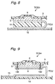
- the heat connecting structure TCS of the present invention Referring to the main section view shown in Fig.7, another embodiment of the heat connecting structure TCS of the present invention will be described.
- the circuit board 3, the CPU 4, the heatsink 5, and the heat conducting unit TCU in the heat generating part are the same as those in the heat connecting structure TCS1 shown in Fig.6.
- a plate-like sol foamed soft sheet 11 is fixed on the circuit component 10 on the circuit board 3, and the heat conducting unit TCU is sandwiched between the metal frame 12 made of a magnesium alloy and the plate-like sol foamed soft sheet 11 so that the heat conducting unit TCU is pressed against the magnesium-alloy metal frame 12 by the elasticity of the plate-like sol foamed soft sheet 11.
- the plate-like sol foamed soft sheet 11 is fixed on the circuit component 10 in this example, the plate-like sol foamed soft sheet 11 may be fixed directly onto the circuit board 3.
- a heat dissipating measure can be completed only by fabricating the heat radiating parts on the substrate side and incorporating this substrate into the frame, thus reducing the number of assembly steps.
- the heat connecting structure TCS3 of this embodiment the circuit board 3, the CPU 4, the heatsink 5, the heat conducting unit TCU, and the structure for connecting heat in the heat generating part are the same as those in the heat connecting structure TCS1 shown in Fig.6.
- the heat conducting unit TCU is sandwiched between the heatsink 5 and the plate-like sol foamed soft sheet 11 and pressed on the heatsink 5 by utilizing the elasticity of the plate-like sol foamed soft sheet 11.
- the heat conducting unit TCU is sandwiched between the magnesium-alloy metal frame 12 and the plate-like sol foamed soft sheet 11 and thus pressed against over the metal frame 12 by utilizing the elasticity of the plate-like sol foamed soft sheet 11.
- the plate-like sol foamed soft sheet 11 simultaneously presses the heat conducting unit TCU in both of the heat generating and heat dissipating parts, which reduces the number of parts and the number of assembly steps.
- the heat connecting structure TCS of the present invention will be described.
- the circuit board 3, the CPU 4, the heatsink 5, the flat plate 6, the heat conducting unit TCU, and the structure for thermal connection are the same as those in the heat connecting structure TCS1 shown in Fig.6.
- the heat conducting unit TCU is sandwiched between a-resin frame 14 of the electronic apparatus and a radiation board 15 stuck on the bottom wall of the resin frame, and the radiation board 15 and the frame 14 are fixed by thermal compression bonding.
- This structure reduces the number of parts and the number of assembly steps.
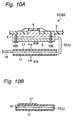
- FIG.10A shows a section of the main part of a heat connecting structure TCS5 of this embodiment
- Fig.10B shows the section XB-XB shown in Fig.10A.
- the circuit board 3, the CPU 4, the heatsink 5, the flat plate 6, the heat conducting unit TCU, and the structure for thermal connection are the same as those of the heat connecting structure TCS1 shown in Fig.6.
- thermo connector in the heat dissipating part of the heat connecting structure TCS5, one end of the heat conducting unit TCU is pressed against a large-area radiation board 16 and wound and fixed with adhesive tape 17.
- This structure efficiently transfers heat from the CPU 4 to the radiation board 16.
- a heat-shrinkable tube may be used instead of the adhesive tape.
- the simple structure of the thermal connector enables reduction in the number of assembly steps and reduction in material cost.
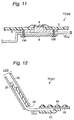
- the heat connecting structure TCS of the present invention will be described.
- the circuit board 3, the CPU 4, the heatsink 5, the flat plate 6, and the heat conducting unit TCU are the same as those in the heat connecting structure TCS1 shown in Fig.6.
- the heat connecting structure of this embodiment is realized by fastening the heatsink 5 and the flat plate 6 with screws, with part of the heat conducting unit TCU sandwiched between the heatsink 5 and the flat plate 6.
- the two ends of the heat conducting unit TCU are extended to given positions not shown and function as a heat dissipating part.
- heat from the CPU 4 is conducted to the heat conducting unit TCU, and both ends of the heat conducting unit TCU are used as a heat dissipating part. Since the heat conducting unit TCU has much higher thermal conductivity than copper and aluminum and smaller specific gravity as stated above, it is possible to realize a heat connecting structure with smaller heat dissipating area and lighter weight as compared with conventional heat radiating structures.
- heat connecting structure TCS7 of this embodiment one end of the heat conducting unit TCU is pressed against the back plate 19 of keyboard and stuck and fixed with adhesive tape 21. Heat from the highly heat generating CPU (not shown) is directly transferred to the back plate 19 of the keyboard, as a heat generating part. The other end of the heat conducting unit TCU is pressed against the metal body 22 of the LCD unit, and stuck and fixed with adhesive tape 21.
- the heat conducting unit TCU having flexibility can be used in movable part for rotatively fixing the LCD unit to the main body in a notebook-sized personal computer, for example.
- the use of the flexible graphite sheets prevents vibration transferred to the heat dissipating part from being further transferred to the heat generating part, which prevents the trouble of damaging the main component like a CPU or an HDD.
- the heat conducting unit is fabricated by previously processing graphite sheets into desired shape (for example, final shape in which the heat conducting unit is incorporated into an electronic apparatus), or forming a graphite block into desired shape, and then covering it with said sheet-like high-molecular compound, which considerably facilitates assembly of the electronic apparatus, without the need of bending the heat conducting unit in assembly.
- a heat generating part and the heat conducting unit of the present invention or a heat dissipating part and the heat conducting unit of the present invention are connected by sandwiching it with metal or resin or by covering it with adhesive tape, which reduces connective thermal resistance between the heat generating part and the heat conducting unit of the present invention and the connective thermal resistance between the heat dissipating part and the heat conducting unit of the present invention.
- the area of the heat dissipating part can be reduced, leading to weight and size reduction of the electronic apparatus.
- the heat conducting unit of the present invention When the heat conducting unit of the present invention is utilized as a heat dissipating part, the heat conducting unit of the present invention having higher thermal conductivity than copper and aluminum allows reduction in heat dissipating area and reduction in weight, as compared with radiation boards of such materials.
- the present invention can be used in a heat conducting cooling system for cooling the interior of the electronic apparatus by efficiently transferring heat generated in the electronic apparatus to a lower-temperature part.
Description
Claims (2)
- A heat conduction unit (TCU) for use with a high temperature part and a low temperature part, and for use in transferring heat generated in the high temperature part to the low temperature part via a heat path, said heat conducting unit (TCU) comprising:wherein said at least one graphite sheet (GS) is to be thermally connected to the high temperature part and the low temperature part and is to be shaped in accordance with the heat path;at least one flexible graphite sheet (GS), capable of being shaped in accordance with the heat path,
characterized in that said flexible graphite sheet is located in a container (20) composed of a flexible sheet (Cb, Ct) and is thermally connected to said flexible container sheet (Cb, Ct); and said flexible container sheet (Cb, Ct) is composed of polyester having a thickness of 20 to 30 µm. - The heat conducting unit (TCU) as claimed in claim 1, wherein a rim (18, 20) is formed around said container (C) to strengthen said container (C).
Applications Claiming Priority (3)
| Application Number | Priority Date | Filing Date | Title |
|---|---|---|---|
| JP28013497 | 1997-10-14 | ||
| JP28013497 | 1997-10-14 | ||
| PCT/JP1998/004568 WO1999019908A1 (en) | 1997-10-14 | 1998-10-12 | Thermal conductive unit and thermal connection structure using same |
Publications (3)
| Publication Number | Publication Date |
|---|---|
| EP0971407A1 EP0971407A1 (en) | 2000-01-12 |
| EP0971407A4 EP0971407A4 (en) | 2001-07-04 |
| EP0971407B1 true EP0971407B1 (en) | 2004-07-21 |
Family
ID=17620821
Family Applications (1)
| Application Number | Title | Priority Date | Filing Date |
|---|---|---|---|
| EP98947805A Expired - Lifetime EP0971407B1 (en) | 1997-10-14 | 1998-10-12 | Thermal conductive unit and thermal connection structure using same |
Country Status (5)
| Country | Link |
|---|---|
| US (1) | US6257328B1 (en) |
| EP (1) | EP0971407B1 (en) |
| DE (1) | DE69825153D1 (en) |
| TW (1) | TW459173B (en) |
| WO (1) | WO1999019908A1 (en) |
Families Citing this family (88)
| Publication number | Priority date | Publication date | Assignee | Title |
|---|---|---|---|---|
| US6482520B1 (en) * | 2000-02-25 | 2002-11-19 | Jing Wen Tzeng | Thermal management system |
| US7077526B2 (en) * | 2001-09-28 | 2006-07-18 | Texas Instruments Incorporated | Mechanically adjustable thermal path for projection display device cooling |
| AT411808B (en) * | 2002-03-25 | 2004-05-25 | Siemens Ag Oesterreich | ELECTRONIC DEVICE |
| DE10234500A1 (en) * | 2002-07-23 | 2004-02-19 | Siemens Ag | Heat extraction in mobile radio equipment involves bringing electrical components into heat extraction contact with metal film with corrugated and/or honeycomb structure in contact with cooling body |
| US6721182B1 (en) | 2002-10-10 | 2004-04-13 | Harris Corporation | Circuit card module including mezzanine card heat sink and related methods |
| US7824368B2 (en) * | 2003-06-19 | 2010-11-02 | Ethicon Endo-Surgery, Inc. | Method for endoscopic, transgastric access into the abdominal cavity |
| US6765798B1 (en) | 2003-06-19 | 2004-07-20 | Curtiss-Wright Controls, Inc. | Electronic thermal management utilizing device with deflectable, two-leg conductive member; and with elastic, thermally-conductive material there between |
| US7086458B2 (en) * | 2003-07-29 | 2006-08-08 | Uniwill Computer Corp. | Heat sink structure with flexible heat dissipation pad |
| JP2005057088A (en) * | 2003-08-05 | 2005-03-03 | Agilent Technol Inc | Heat-conductive member of multilayer structure and electronic apparatus using it |
| US7292441B2 (en) * | 2003-11-25 | 2007-11-06 | Advanced Energy Technology Inc. | Thermal solution for portable electronic devices |
| US6982874B2 (en) * | 2003-11-25 | 2006-01-03 | Advanced Energy Technology Inc. | Thermal solution for electronic devices |
| US7280359B2 (en) * | 2003-12-11 | 2007-10-09 | Matsushita Electric Industrial Co., Ltd. | Heat-radiating structure of electronic apparatus |
| JP4729296B2 (en) * | 2003-12-11 | 2011-07-20 | パナソニック株式会社 | Heat dissipation structure for electronic equipment |
| US20050150649A1 (en) * | 2004-01-13 | 2005-07-14 | Japan Matex Kabushiki Kaisha (Japan Corporation) | Heat release sheet and heat sink |
| JP2005228954A (en) * | 2004-02-13 | 2005-08-25 | Fujitsu Ltd | Heat conduction mechanism, heat dissipation system, and communication apparatus |
| US7393587B2 (en) * | 2004-09-17 | 2008-07-01 | Graftech International Holdings Inc. | Sandwiched finstock |
| US7799428B2 (en) * | 2004-10-06 | 2010-09-21 | Graftech International Holdings Inc. | Sandwiched thermal solution |
| TWI247574B (en) * | 2004-11-30 | 2006-01-11 | Silicon Integrated Sys Corp | Heat dissipation mechanism for electronic device |
| JP2006234669A (en) * | 2005-02-25 | 2006-09-07 | Advantest Corp | Heat transfer body, test board, and testing device |
| JP4299261B2 (en) * | 2005-03-31 | 2009-07-22 | 東洋炭素株式会社 | Method of using heat transfer sheet, heat dissipation structure and heat transfer sheet |
| US20060225870A1 (en) * | 2005-04-12 | 2006-10-12 | The Boeing Company | Cooling apparatus, system, and associated method |
| KR100880388B1 (en) * | 2005-04-20 | 2009-01-23 | 주식회사 엘지화학 | Housing Member For Battery Module |
| DE102005049872B4 (en) * | 2005-10-18 | 2010-09-23 | Continental Automotive Gmbh | IC component with cooling arrangement |
| KR101029021B1 (en) * | 2005-12-02 | 2011-04-14 | 주식회사 엘지화학 | Battery Module of High Cooling Efficiency |
| CN1988785A (en) * | 2005-12-23 | 2007-06-27 | 鸿富锦精密工业(深圳)有限公司 | Heat radiator |
| AT9009U1 (en) * | 2006-02-01 | 2007-04-15 | Emcools Emergency Medical Cool | DEVICE FOR COOLING THE BODY OF PERSONS OR DERGL. |
| US20080218964A1 (en) * | 2007-03-05 | 2008-09-11 | Dfi, Inc. | Desktop personal computer and thermal module thereof |
| EP2498288A3 (en) * | 2007-03-12 | 2014-04-23 | Toyo Tanso Co., Ltd. | Circuit board using heat radiating member, electronic module and method for manufacturing the module |
| US20090080163A1 (en) * | 2007-05-17 | 2009-03-26 | Lockheed Martin Corporation | Printed wiring board assembly |
| US8051896B2 (en) * | 2007-07-31 | 2011-11-08 | Adc Telecommunications, Inc. | Apparatus for spreading heat over a finned surface |
| US8235094B2 (en) * | 2007-07-31 | 2012-08-07 | Adc Telecommunications, Inc. | Apparatus for transferring heat in a fin of a heat sink |
| US20090032218A1 (en) * | 2007-07-31 | 2009-02-05 | Adc Telecommunications, Inc. | Apparatus for transferring between two heat conducting surfaces |
| US7964291B2 (en) * | 2007-08-27 | 2011-06-21 | Jiing Tung Tec. Metal Co., Ltd. | Magnesium alloy compound type thermal metal material |
| US8628872B2 (en) * | 2008-01-18 | 2014-01-14 | Lg Chem, Ltd. | Battery cell assembly and method for assembling the battery cell assembly |
| US8426050B2 (en) * | 2008-06-30 | 2013-04-23 | Lg Chem, Ltd. | Battery module having cooling manifold and method for cooling battery module |
| US8486552B2 (en) * | 2008-06-30 | 2013-07-16 | Lg Chem, Ltd. | Battery module having cooling manifold with ported screws and method for cooling the battery module |
| US7883793B2 (en) * | 2008-06-30 | 2011-02-08 | Lg Chem, Ltd. | Battery module having battery cell assemblies with alignment-coupling features |
| JP2010176756A (en) * | 2009-01-30 | 2010-08-12 | Hitachi Ltd | Magnetic disk device |
| JP4676008B2 (en) * | 2009-03-30 | 2011-04-27 | 株式会社東芝 | Electronics |
| DE102009015757A1 (en) * | 2009-04-01 | 2010-10-14 | Siemens Aktiengesellschaft | Pressure support for an electronic circuit |
| US9337456B2 (en) * | 2009-04-20 | 2016-05-10 | Lg Chem, Ltd. | Frame member, frame assembly and battery cell assembly made therefrom and methods of making the same |
| US8663828B2 (en) * | 2009-04-30 | 2014-03-04 | Lg Chem, Ltd. | Battery systems, battery module, and method for cooling the battery module |
| US8852778B2 (en) * | 2009-04-30 | 2014-10-07 | Lg Chem, Ltd. | Battery systems, battery modules, and method for cooling a battery module |
| US8663829B2 (en) * | 2009-04-30 | 2014-03-04 | Lg Chem, Ltd. | Battery systems, battery modules, and method for cooling a battery module |
| US20110063801A1 (en) * | 2009-09-14 | 2011-03-17 | Lin li-tang | Electronic device with a heat insulating structure |
| TW201116983A (en) * | 2009-11-06 | 2011-05-16 | Nat Univ Tsing Hua | Heat dissipation structure of electronic apparatus |
| US9147916B2 (en) | 2010-04-17 | 2015-09-29 | Lg Chem, Ltd. | Battery cell assemblies |
| US8920956B2 (en) | 2010-08-23 | 2014-12-30 | Lg Chem, Ltd. | Battery system and manifold assembly having a manifold member and a connecting fitting |
| US8758922B2 (en) | 2010-08-23 | 2014-06-24 | Lg Chem, Ltd. | Battery system and manifold assembly with two manifold members removably coupled together |
| US8353315B2 (en) | 2010-08-23 | 2013-01-15 | Lg Chem, Ltd. | End cap |
| US8469404B2 (en) | 2010-08-23 | 2013-06-25 | Lg Chem, Ltd. | Connecting assembly |
| US9005799B2 (en) | 2010-08-25 | 2015-04-14 | Lg Chem, Ltd. | Battery module and methods for bonding cell terminals of battery cells together |
| US8662153B2 (en) | 2010-10-04 | 2014-03-04 | Lg Chem, Ltd. | Battery cell assembly, heat exchanger, and method for manufacturing the heat exchanger |
| US8288031B1 (en) | 2011-03-28 | 2012-10-16 | Lg Chem, Ltd. | Battery disconnect unit and method of assembling the battery disconnect unit |
| JP5553056B2 (en) * | 2011-04-28 | 2014-07-16 | 株式会社デンソー | Electronic equipment |
| US9178192B2 (en) | 2011-05-13 | 2015-11-03 | Lg Chem, Ltd. | Battery module and method for manufacturing the battery module |
| JP2013004783A (en) * | 2011-06-17 | 2013-01-07 | Sony Corp | Heat radiation structure and display device |
| US9496544B2 (en) | 2011-07-28 | 2016-11-15 | Lg Chem. Ltd. | Battery modules having interconnect members with vibration dampening portions |
| JP5845835B2 (en) * | 2011-11-14 | 2016-01-20 | 株式会社デンソー | Semiconductor module |
| US8780559B2 (en) * | 2011-12-29 | 2014-07-15 | General Electric Company | Heat exchange assembly for use with electrical devices and methods of assembling an electrical device |
| JP6008117B2 (en) * | 2012-02-15 | 2016-10-19 | パナソニックIpマネジメント株式会社 | Graphite structure and electronic device using the same |
| JP5978457B2 (en) * | 2012-03-19 | 2016-08-24 | パナソニックIpマネジメント株式会社 | Thermal conductor |
| US20150096731A1 (en) * | 2013-10-04 | 2015-04-09 | Specialty Minerals (Michigan) Inc. | Device and System for Dissipating Heat, and Method of Making Same |
| US20150168078A1 (en) * | 2013-12-13 | 2015-06-18 | Asia Vital Components Co., Ltd. | Vapor Chamber Structure |
| JPWO2015155940A1 (en) * | 2014-04-08 | 2017-04-13 | パナソニックIpマネジメント株式会社 | Thermal conductive sheet and manufacturing method |
| US10458716B2 (en) | 2014-11-04 | 2019-10-29 | Roccor, Llc | Conformal thermal ground planes |
| JP6432295B2 (en) * | 2014-11-11 | 2018-12-05 | 日本電気株式会社 | Waste heat device |
| US10028418B2 (en) | 2015-01-20 | 2018-07-17 | Microsoft Technology Licensing, Llc | Metal encased graphite layer heat pipe |
| US9791704B2 (en) * | 2015-01-20 | 2017-10-17 | Microsoft Technology Licensing, Llc | Bonded multi-layer graphite heat pipe |
| US10444515B2 (en) | 2015-01-20 | 2019-10-15 | Microsoft Technology Licensing, Llc | Convective optical mount structure |
| US10108017B2 (en) | 2015-01-20 | 2018-10-23 | Microsoft Technology Licensing, Llc | Carbon nanoparticle infused optical mount |
| JP6543803B2 (en) * | 2015-05-18 | 2019-07-17 | パナソニックIpマネジメント株式会社 | Thermal conduction sheet |
| US20160377356A1 (en) * | 2015-06-25 | 2016-12-29 | Asia Vital Components Co., Ltd. | Flexible and transformable water-cooling device |
| US10299407B2 (en) | 2015-06-29 | 2019-05-21 | Microsoft Technology Licensing, Llc | Differently oriented layered thermal conduit |
| US9743554B2 (en) | 2015-11-18 | 2017-08-22 | Microsoft Technology Licensing, Llc | Heat dissipation in electronics with a heat spreader |
| JP6497326B2 (en) * | 2016-01-18 | 2019-04-10 | 三菱電機株式会社 | Thermal connection structure, exhaust heat structure |
| US11059278B2 (en) | 2016-02-28 | 2021-07-13 | Roccor, Llc | Two-phase thermal management devices, methods, and systems |
| US11306974B2 (en) * | 2016-06-15 | 2022-04-19 | Delta Electronics, Inc. | Temperature plate and heat dissipation device |
| US11543188B2 (en) | 2016-06-15 | 2023-01-03 | Delta Electronics, Inc. | Temperature plate device |
| WO2018142879A1 (en) * | 2017-02-06 | 2018-08-09 | パナソニックIpマネジメント株式会社 | Heat conductive sheet and multilayered heat conductive sheet |
| JP6446489B2 (en) * | 2017-03-10 | 2018-12-26 | 東芝電波プロダクツ株式会社 | Heat spreader |
| US10206310B2 (en) * | 2017-04-07 | 2019-02-12 | Toyota Motor Engineering & Manufacturing North America, Inc. | Electronics assemblies incorporating three-dimensional heat flow structures |
| US10225955B1 (en) * | 2018-02-23 | 2019-03-05 | Microsoft Technology Licensing, Llc | Enclosure thermal short |
| EP3540770B1 (en) * | 2018-03-15 | 2022-06-01 | Aptiv Technologies Limited | Heat transfer device |
| US20190301809A1 (en) * | 2018-04-03 | 2019-10-03 | Aavid Thermalloy, Llc | Wrap around heat exchanger |
| US11143460B2 (en) * | 2018-07-11 | 2021-10-12 | Asia Vital Components Co., Ltd. | Vapor chamber structure |
| WO2021249970A1 (en) * | 2020-06-11 | 2021-12-16 | Signify Holding B.V. | Vapor chamber assembly |
| TWM603524U (en) * | 2020-07-27 | 2020-11-01 | 華碩電腦股份有限公司 | Heat transfer device |
Family Cites Families (25)
| Publication number | Priority date | Publication date | Assignee | Title |
|---|---|---|---|---|
| US640534A (en) * | 1898-10-01 | 1900-01-02 | Lyman Cheney | Warming-pad. |
| US4602678A (en) * | 1983-09-02 | 1986-07-29 | The Bergquist Company | Interfacing of heat sinks with electrical devices, and the like |
| US4849858A (en) * | 1986-10-20 | 1989-07-18 | Westinghouse Electric Corp. | Composite heat transfer means |
| FR2616997B1 (en) * | 1987-06-16 | 1989-08-25 | Thomson Csf | SUPPORT FOR A PRINTED CIRCUIT, FORMING A THERMAL DRAIN WITH CONTROLLED EXPANSION, AND MANUFACTURING METHOD |
| US4963414A (en) * | 1989-06-12 | 1990-10-16 | General Electric Company | Low thermal expansion, heat sinking substrate for electronic surface mount applications |
| US5195021A (en) * | 1989-08-21 | 1993-03-16 | Texas Instruments Incorporated | Constraining core for surface mount technology |
| JPH03104262A (en) * | 1989-09-19 | 1991-05-01 | Fujitsu Ltd | Vibration proof heat transfer structure |
| FR2654387B1 (en) * | 1989-11-16 | 1992-04-10 | Lorraine Carbone | MULTILAYER MATERIAL COMPRISING FLEXIBLE GRAPHITE MECHANICALLY, ELECTRICALLY AND THERMALLY REINFORCED BY A METAL AND METHOD OF MANUFACTURE. |
| US5095404A (en) * | 1990-02-26 | 1992-03-10 | Data General Corporation | Arrangement for mounting and cooling high density tab IC chips |
| US5000256A (en) * | 1990-07-20 | 1991-03-19 | Minnesota Mining And Manufacturing Company | Heat transfer bag with thermal via |
| US5255738A (en) * | 1992-07-16 | 1993-10-26 | E-Systems, Inc. | Tapered thermal substrate for heat transfer applications and method for making same |
| EP1056129A3 (en) * | 1992-08-06 | 2002-01-30 | Pfu Limited | Heat-generating element cooling device |
| US5343940A (en) * | 1992-10-29 | 1994-09-06 | Amigo Jean | Flexible heat transfer device |
| DE4336961C2 (en) * | 1993-10-29 | 2000-07-06 | Kerafol Keramische Folien Gmbh | Flexible heat transfer device |
| US5542471A (en) * | 1993-11-16 | 1996-08-06 | Loral Vought System Corporation | Heat transfer element having the thermally conductive fibers |
| JPH0823183A (en) | 1994-07-06 | 1996-01-23 | Matsushita Electric Ind Co Ltd | Structure of cooling member |
| US5560423A (en) * | 1994-07-28 | 1996-10-01 | Aavid Laboratories, Inc. | Flexible heat pipe for integrated circuit cooling apparatus |
| JPH08267647A (en) | 1995-01-11 | 1996-10-15 | Matsushita Electric Ind Co Ltd | Graphite-clad structural material and graphite part using it |
| JPH0955456A (en) * | 1995-08-15 | 1997-02-25 | Shin Etsu Polymer Co Ltd | Semiconductor device cooling structure |
| JPH09156913A (en) | 1995-11-30 | 1997-06-17 | Matsushita Electric Ind Co Ltd | Production of heat-conductive sheet and sputtering apparatus using the sheet |
| US5729433A (en) * | 1996-01-30 | 1998-03-17 | Micromodule Systems, Inc. | Multiple chip module assembly for top of mother board |
| AT404532B (en) * | 1996-02-13 | 1998-12-28 | Electrovac | HEAT SINK FOR ELECTRICAL AND ELECTRONIC COMPONENTS |
| JPH09262917A (en) * | 1996-03-28 | 1997-10-07 | Mitsubishi Electric Corp | Heat transfer element |
| US5902762A (en) * | 1997-04-04 | 1999-05-11 | Ucar Carbon Technology Corporation | Flexible graphite composite |
| US5958572A (en) * | 1997-09-30 | 1999-09-28 | Motorola, Inc. | Hybrid substrate for cooling an electronic component |
-
1998
- 1998-10-12 DE DE69825153T patent/DE69825153D1/en not_active Expired - Lifetime
- 1998-10-12 WO PCT/JP1998/004568 patent/WO1999019908A1/en active IP Right Grant
- 1998-10-12 EP EP98947805A patent/EP0971407B1/en not_active Expired - Lifetime
- 1998-10-12 US US09/319,774 patent/US6257328B1/en not_active Expired - Lifetime
- 1998-10-14 TW TW087117004A patent/TW459173B/en not_active IP Right Cessation
Also Published As
| Publication number | Publication date |
|---|---|
| DE69825153D1 (en) | 2004-08-26 |
| WO1999019908A1 (en) | 1999-04-22 |
| EP0971407A4 (en) | 2001-07-04 |
| EP0971407A1 (en) | 2000-01-12 |
| US6257328B1 (en) | 2001-07-10 |
| TW459173B (en) | 2001-10-11 |
Similar Documents
| Publication | Publication Date | Title |
|---|---|---|
| EP0971407B1 (en) | Thermal conductive unit and thermal connection structure using same | |
| US9222735B2 (en) | Compliant multilayered thermally-conductive interface assemblies | |
| KR101538944B1 (en) | Compliant multilayered thermally-conductive interface assemblies and memory modules including the same | |
| US5513070A (en) | Dissipation of heat through keyboard using a heat pipe | |
| US7623349B2 (en) | Thermal management apparatus and method for a circuit substrate | |
| US6097598A (en) | Thermal conductive member and electronic device using same | |
| US5847925A (en) | System and method for transferring heat between movable portions of a computer | |
| KR101017452B1 (en) | Semiconductor package | |
| US6888719B1 (en) | Methods and apparatuses for transferring heat from microelectronic device modules | |
| WO2014021046A1 (en) | Electronic apparatus and heat conductive sheet | |
| US20100321897A1 (en) | Compliant multilayered thermally-conductive interface assemblies | |
| JP2003168882A (en) | Heat conductive sheet | |
| JP2003188323A (en) | Graphite sheet and its manufacturing method | |
| EP2012355A2 (en) | Heat dissipation plate and semiconductor device | |
| JP2007044994A (en) | Graphite composite structure, heat radiation member using the structure, and electronic component using the structure | |
| US20020015288A1 (en) | High performance thermal/mechanical interface for fixed-gap references for high heat flux and power semiconductor applications | |
| JP2007184392A (en) | Thermoconductive structural body, and heat dissipating memeber and electronic device using the same | |
| JPS596565A (en) | Heat conductive structure | |
| EP3583622B1 (en) | Thermal dissipation and electrical isolating device | |
| JPH1158591A (en) | Heat-conductive sheet | |
| JPS6132819B2 (en) | ||
| TW200423345A (en) | Thermal-conductive substrate package | |
| US7111674B2 (en) | Heat dissipating housing with interlocking chamfers and ESD resistance | |
| JP4085342B2 (en) | Thermal conductive component and thermal connection structure using the same | |
| CN213459708U (en) | Heat sink for chip on film package |
Legal Events
| Date | Code | Title | Description |
|---|---|---|---|
| PUAI | Public reference made under article 153(3) epc to a published international application that has entered the european phase |
Free format text: ORIGINAL CODE: 0009012 |
|
| 17P | Request for examination filed |
Effective date: 19990623 |
|
| AK | Designated contracting states |
Kind code of ref document: A1 Designated state(s): DE FR GB IT SE |
|
| A4 | Supplementary search report drawn up and despatched |
Effective date: 20010518 |
|
| AK | Designated contracting states |
Kind code of ref document: A4 Designated state(s): DE FR GB IT SE |
|
| RIC1 | Information provided on ipc code assigned before grant |
Free format text: 7H 01L 23/36 A, 7H 01L 23/373 B, 7H 05K 1/05 B |
|
| 17Q | First examination report despatched |
Effective date: 20020605 |
|
| GRAP | Despatch of communication of intention to grant a patent |
Free format text: ORIGINAL CODE: EPIDOSNIGR1 |
|
| GRAS | Grant fee paid |
Free format text: ORIGINAL CODE: EPIDOSNIGR3 |
|
| GRAA | (expected) grant |
Free format text: ORIGINAL CODE: 0009210 |
|
| AK | Designated contracting states |
Kind code of ref document: B1 Designated state(s): DE FR GB IT SE |
|
| PG25 | Lapsed in a contracting state [announced via postgrant information from national office to epo] |
Ref country code: IT Free format text: LAPSE BECAUSE OF FAILURE TO SUBMIT A TRANSLATION OF THE DESCRIPTION OR TO PAY THE FEE WITHIN THE PRESCRIBED TIME-LIMIT;WARNING: LAPSES OF ITALIAN PATENTS WITH EFFECTIVE DATE BEFORE 2007 MAY HAVE OCCURRED AT ANY TIME BEFORE 2007. THE CORRECT EFFECTIVE DATE MAY BE DIFFERENT FROM THE ONE RECORDED. Effective date: 20040721 Ref country code: FR Free format text: LAPSE BECAUSE OF FAILURE TO SUBMIT A TRANSLATION OF THE DESCRIPTION OR TO PAY THE FEE WITHIN THE PRESCRIBED TIME-LIMIT Effective date: 20040721 |
|
| REG | Reference to a national code |
Ref country code: GB Ref legal event code: FG4D |
|
| REF | Corresponds to: |
Ref document number: 69825153 Country of ref document: DE Date of ref document: 20040826 Kind code of ref document: P |
|
| PG25 | Lapsed in a contracting state [announced via postgrant information from national office to epo] |
Ref country code: SE Free format text: LAPSE BECAUSE OF FAILURE TO SUBMIT A TRANSLATION OF THE DESCRIPTION OR TO PAY THE FEE WITHIN THE PRESCRIBED TIME-LIMIT Effective date: 20041021 |
|
| PG25 | Lapsed in a contracting state [announced via postgrant information from national office to epo] |
Ref country code: DE Free format text: LAPSE BECAUSE OF FAILURE TO SUBMIT A TRANSLATION OF THE DESCRIPTION OR TO PAY THE FEE WITHIN THE PRESCRIBED TIME-LIMIT Effective date: 20041022 |
|
| PLBE | No opposition filed within time limit |
Free format text: ORIGINAL CODE: 0009261 |
|
| STAA | Information on the status of an ep patent application or granted ep patent |
Free format text: STATUS: NO OPPOSITION FILED WITHIN TIME LIMIT |
|
| 26N | No opposition filed |
Effective date: 20050422 |
|
| EN | Fr: translation not filed | ||
| REG | Reference to a national code |
Ref country code: GB Ref legal event code: 746 Effective date: 20100127 |
|
| PGFP | Annual fee paid to national office [announced via postgrant information from national office to epo] |
Ref country code: GB Payment date: 20131009 Year of fee payment: 16 |
|
| GBPC | Gb: european patent ceased through non-payment of renewal fee |
Effective date: 20141012 |
|
| PG25 | Lapsed in a contracting state [announced via postgrant information from national office to epo] |
Ref country code: GB Free format text: LAPSE BECAUSE OF NON-PAYMENT OF DUE FEES Effective date: 20141012 |