EP0971292A2 - Verfahren und Vorrichtung zur Übertragung von Daten über einen Prozessorschnittstellenbus - Google Patents
Verfahren und Vorrichtung zur Übertragung von Daten über einen Prozessorschnittstellenbus Download PDFInfo
- Publication number
- EP0971292A2 EP0971292A2 EP99112450A EP99112450A EP0971292A2 EP 0971292 A2 EP0971292 A2 EP 0971292A2 EP 99112450 A EP99112450 A EP 99112450A EP 99112450 A EP99112450 A EP 99112450A EP 0971292 A2 EP0971292 A2 EP 0971292A2
- Authority
- EP
- European Patent Office
- Prior art keywords
- data
- processor interface
- bus
- interface bus
- signal
- Prior art date
- Legal status (The legal status is an assumption and is not a legal conclusion. Google has not performed a legal analysis and makes no representation as to the accuracy of the status listed.)
- Ceased
Links
Images


Classifications
-
- G—PHYSICS
- G06—COMPUTING OR CALCULATING; COUNTING
- G06F—ELECTRIC DIGITAL DATA PROCESSING
- G06F13/00—Interconnection of, or transfer of information or other signals between, memories, input/output devices or central processing units
- G06F13/38—Information transfer, e.g. on bus
-
- G—PHYSICS
- G06—COMPUTING OR CALCULATING; COUNTING
- G06F—ELECTRIC DIGITAL DATA PROCESSING
- G06F12/00—Accessing, addressing or allocating within memory systems or architectures
- G06F12/02—Addressing or allocation; Relocation
- G06F12/08—Addressing or allocation; Relocation in hierarchically structured memory systems, e.g. virtual memory systems
- G06F12/0802—Addressing of a memory level in which the access to the desired data or data block requires associative addressing means, e.g. caches
- G06F12/0806—Multiuser, multiprocessor or multiprocessing cache systems
- G06F12/0815—Cache consistency protocols
- G06F12/0831—Cache consistency protocols using a bus scheme, e.g. with bus monitoring or watching means
- G06F12/0833—Cache consistency protocols using a bus scheme, e.g. with bus monitoring or watching means in combination with broadcast means (e.g. for invalidation or updating)
-
- G—PHYSICS
- G06—COMPUTING OR CALCULATING; COUNTING
- G06F—ELECTRIC DIGITAL DATA PROCESSING
- G06F15/00—Digital computers in general; Data processing equipment in general
- G06F15/16—Combinations of two or more digital computers each having at least an arithmetic unit, a program unit and a register, e.g. for a simultaneous processing of several programs
- G06F15/163—Interprocessor communication
- G06F15/17—Interprocessor communication using an input/output type connection, e.g. channel, I/O port
Definitions
- This invention relates generally to transferring data, and more specifically to transferring data over a processor interface bus.
- bus protocols are typically used to handle data transfer for local bus slave devices which contain cacheable or non-cacheable data that does not reside in main memory.
- a separate bus protocol is typically used for transferring cacheable data residing in main memory directly from one cache to another. Since each of the various bus protocols has a different set of control pins, the more protocols that are used within a system, the more control pins are required as well, thereby increasing system costs and complexity. Therefore, there is a need for a more efficient and less expensive bus protocol to support both cache-to-cache transfers and data transfers involving a local bus slave device.
- the present invention relates to a method and apparatus for transferring data over a processor interface bus.
- the method relates to transferring data between a slave device in communication with a processor interface bus, where the processor interface bus is in communication with a master device.
- the method includes the steps of receiving an address from the processor interface bus that was provided by the master device, asserting a first signal on the processor interface bus to indicate that the slave device is servicing the associated data transfer transaction, and asserting a second signal on the processor interface bus to indicate whether data to be transferred using the processor interface bus is to be stored in main memory by a main memory controller in communication with the processor interface bus.
- the data is then transferred between the slave device and the processor interface bus.
- the method in another embodiment, relates to transferring data between a slave device in communication with a processor interface bus, where the processor interface bus is in communication with a master device.
- the method includes receiving an address from the processor interface bus where the address is provided by the master device, asserting a first signal on the processor interface bus to indicate that the slave device is servicing the associated data transfer transaction, and asserting a second signal on the processor interface bus to indicate whether data to be transferred using the processor interface bus is to be stored in main memory by a main memory controller in communication with the processor interface bus.
- a third signal is asserted on the processor interface bus to indicate that the slave device is ready to perform the data transfer transaction. The data is then transferred between the slave device and the processor interface bus.
- the method relates to transferring data from an external source to a processor interface bus in communication with a plurality of devices.
- the method includes receiving data and an associated memory address at a controller responsive to the processor interface bus from an external data source. After determining whether the associated memory address is within a memory range for the plurality of devices, a write transaction is initiated on the processor interface bus, and the processor interface bus is monitored for a plurality of responses from the plurality of devices. Data ready signals are received over the processor interface bus from a subset of the plurality of devices. The processor interface bus is controlled and access is granted for the processor interface bus to the subset of the plurality of devices. The data received from the external data source is then transferred to the processor interface bus.
- the apparatus is a data processing system that includes a processor interface bus, a memory controller responsive to the processor interface bus, a memory device responsive to the memory controller, a first device responsive to the processor interface bus operating as a master device, and a second device.
- the second device is responsive to the processor interface bus operating as a slave device and asserts a first signal on the processor interface bus to indicate that the slave device is servicing a data transfer transaction.
- the second device asserts a second signal on the processor interface bus to indicate whether data to be transferred using the processor interface bus is to be stored in the memory device by the main memory controller.
- bus 38 is a peripheral I/O bus. Alternate embodiments may include the address, data, and memory controllers as separate units outside of chip set 32, or may include all such controllers integrated within a single controller. Chip set 32 functions similarly to the chip sets found in modern desktop computer systems. Therefore, the specific functions and design of the chip set depend on the system in which it is used. The operation of data system 10 shown in FIG. 1 will be further described in reference to FIGs. 2-7.
- bus 34 of FIG. 1 contains two portions: an address bus 50 and its associated control and attribute bits and a data bus 60 with its associated control bits.
- the address and data buses are de-coupled, but in an alternate embodiment the address and data can be coupled into a single bus structure. Alternate embodiments may also divide the bus into various different portions wherein the control and control and attributes are separate buses or are linked together.
- the bus size depends on the number of address bits, data bits, and control and attribute bits needed for the data processing system 10, and can thus vary from system to system and can be designed accordingly.
- Processor bus 34 functions similarly to those buses found in modern desktop computer systems. Those of ordinary skill in the art will appreciate that bus designs will vary depending on the data processing system's requirements. For example, different control signals may be needed for the processor bus in order to implement the required bus protocols.
- the other devices coupled to bus 34 snoop, or monitor, the address bus 50 to determine whether they need to respond to the master address. For a given transaction, the device requesting the transaction becomes the master, and the device responding to the address becomes the slave which services the master's transaction request.
- the device that contains the data associated with the master address then requests ownership of the data bus 60. Ownership of the data bus 60 allows the device that contains the data to control the information on the data bus 60 during the transaction.
- data transfer phase 110 occurs, and the data is transferred between the master and slave devices. Note that in alternate embodiments, some of the bus phases can occur simultaneously or sequentially in time as required by the design of data processing system 10. Also, in alternate embodiments, bus phases for subsequent transactions can be overlapped (or pipelined) with bus phases for previous transactions. Furthermore, the data transfer phases for different transactions can be reordered with respect to their associated address phases.
- FIG. 4 illustrates a flow diagram 200 depicting an illustrative data transfer transaction over bus 34 using chip set 32.
- Flow diagram 200 begins within snoop response phase 106 of FIG. 3 with decision diamond 202.
- Local bus devices refer to those devices coupled to bus 34, such as device 22, 20, 12, 14, and 18. If no local bus device claims the transaction after snooping the address, chip set 32 then services the transaction itself as shown in block 204. It on the other hand, a local bus device, such as master slave device 22 or other slave device 20, claims the transaction, flow continues to decision diamond 206.
- the local bus device If the local bus device claims the transaction and asserts a snarf signal, the local bus device has accepted a transaction (thus becoming the slave device) and alerted chip set 32 that main memory 36 needs to be updated.
- the local bus slave device asserts the snarf signal when it has modified the data being requested and thus wants to write the updated data to main memory 36 as well as to the requesting device.
- the local bus slave device e.g. a write-through cache
- chip set 32 may default to snarf mode unless a don't_snarf signal is asserted by the slave device. In this case, data is written to main memory 36 unless a signal is asserted to indicate not to snarf.
- the master may be a microprocessor such as one of the microprocessors 12, 14, or 16, or master/slave device 22, and the slave may be another microprocessor, level three cache 18, master/slave device 22, or other slave device 20.
- master/slave device 22 can be a graphics controller with memory 30 as its frame buffer.
- the other slave device 20 can be a cache controller, a memory controller for a memory having addresses outside of main memory 36, or a special purpose coprocessor. Alternate embodiments may also include only one microprocessor and various combinations of master/slave devices and other slave devices.
- FIG. 5 is a flow diagram of a local bus device transferring data using bus 34.
- the local bus device snoops the master's address from the address bus 50, in block 302, and, depending on the device type (decision diamond 304), follows a particular method of determining whether it will service the address with a data transfer. If the local bus device is a cache controller (thus having a caching function), then the local bus device's memory is a subset of main memory 36. For example, in FIG. 1, level two cache 24 and the first cache found within microprocessor 12 are subsets of main memory 36. In this case, memory coherency is a concern between main memory 36 and the subset of main memory 36 such as level two cache 24 or the first cache. If a device requests data, the device that contains the requested data needs to access the most recently updated version of the data.
- the local bus device is a separate memory range controller, then it contains a separate memory range that is not found in main memory 36.
- memory 30 (such as a frame buffer for a graphics controller) can be a separate memory range not found in main memory 36.
- the local bus slave device If intervention is not enabled (decision diamond 308) and the data being requested has not been modified by the local bus slave device (decision diamond 310), then the local bus slave device has completed its transaction, and the master will receive the data from main memory 36 rather than from the local bus slave device. Flow then returns to block 302. However, if the data has been modified, the local bus slave device issues a snoop response indicating a retry request in block 312. A retry request alerts the master that the data in main memory 36 is not the modified version and to wait and retry its transaction request at a later time. The local bus slave device then writes the modified data to main memory 36, in block 314. At this point, the local bus slave device has completed its transaction, and the data within the local bus slave device is no longer marked as modified. Flow then returns to block 302. The master may now re-request its transaction and will read the updated data from main memory 36.
- intervention is enabled at decision diamond 308, transactions directly between local bus devices are allowed. If intervention is enabled and the data being requested has been modified by the local bus slave device (decision diamond 316), the local bus slave device will claim the transaction by asserting a first signal, also referred to as a hit signal, in block 318. The local bus slave device will also assert a second signal, also referred to as a snarf signal, in order to force a write of the modified data value to main memory 36 (block 320). Therefore, even though the master will transfer data directly to or from the local bus slave device, main memory 36 will also receive an updated copy of the data. Flow then continues to the data transfer step in block 326 which is further described below in reference to FIG. 6.
- the intervention protocol not only allows for modified intervention, but for unmodified intervention as well, as illustrated by decision diamond 322.
- Unmodified intervention allows for local bus device transfers even if the data has not been modified by the local bus device and could therefore also be retrieved from main memory 36. If the data has not been modified and unmodified intervention is not enabled, then the local bus slave device has completed its transaction, and the master device will get its information from main memory 36. Flow once again returns to block 302. However, if unmodified intervention is enabled and the data has not been modified by the local bus slave device, the local bus slave device will assert the hit signal without asserting the snarf signal (block 324) so that no snarfing will occur. Snarfing is not necessary in this case because the data was not modified; therefore, no write to main memory 36 is required since main memory 36 already has a most recent version of the data. Flow then continues to the data transfer of block 326.
- the local bus slave device determines at decision diamond 328 that a memory hit occurs if the master address falls within its memory range. If a memory hit occurred and the local bus slave device is responsible for servicing the transaction (decision diamond 330), then the local bus slave device will claim the transaction by asserting the hit signal at block 324. Once again, no snarfing is required since the local bus device's memory range is outside of main memory 36. Thus, a write to main memory 36 is not required and is not desired since the address location does not even exist in main memory 36. At this point, we have reached the data transfer step of block 326.
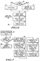
- FIG. 6 illustrates the data transfer step 326 to or from the local bus slave device.
- the local bus slave device fetches the data to be sent to the master device in block 352.
- the transaction is a write
- the local bus slave device prepares to receive the data from the master device, in block 354.
- the slave is the device that will provide the data
- the master is the device that will provide the data.
- the slave device is ready for the transfer to proceed, it will request the data bus 60 by asserting a third signal, also referred to as a data ready signal, in block 356.
- the device providing data to be transferred will wait for access to the data bus 60 (block 358).
- the device that is providing the data transfers the data as shown in block 360 by placing the data on the data bus 60 to be received by the receiving device (and written to its memory or cache).
- the data bus 60 and address bus 50 are decoupled (as shown in FIG. 2) such that the data bus 60 is free to be used by other devices while the local bus slave device fetches the data or prepares to receive the data. In this manner, the data bus 60 is free for other use until the arbitration unit 48 grants ownership of the data bus 60 to the local bus slave device after having received the data ready signal.
- slave devices are assumed to be able to receive data from a master device, during a write transaction, immediately. In this case, it is not necessary for the slave to assert a data ready signal when it claims a write from the master.
- One embodiment of the present invention uses a combination of three signals as described above.
- the hit signal is asserted by the local bus slave device when a memory hit occurs, the data ready signal is sent when the data is ready to be transferred, and the snarf signal is asserted when snarfing is to occur thus allowing the data to be forwarded to main memory 36.
- These signals allow for a single protocol to support both cache-to-cache transfers and reads and writes involving local bus slave devices and main memory 36 (as was described in reference to FIGs. 2-6). Since only three signals are required for this common protocol in this embodiment, no more than three control pins of bus 34 would be necessary to achieve the protocol in data processing system 10.
- only two control pins are used to implement the protocol by time multiplexing the hit signal and the snarf signal onto a single pin by asserting the hit signal for an additional cycle after the snoop response window in order to indicate that data does not need to be snarfed to main memory 36.
- This can be referred to as the extended hit protocol, which requires only one control pin for the hit and snarf signals since they can be asserted sequentially over this common pin.
- the snoop window refers to how long chip set 32 will wait to receive snoop responses from the slave devices snooping the master address.
- this snoop window can be of a fixed length, or it can be programmable within data processing system 10 by the user. In alternate embodiments, different methods may be used to determine when a hit signal or a snarf signal has been asserted by any of the slave devices.
- the above embodiments have several benefits. For example, the use of only two control pins for providing cache to cache transfer and selectible use of writes to main memory lowers both system cost and complexity. Using a single protocol for a variety of differing transactions, such as slave device and inter processor cache transfer, allows for a corresponding variety of differing system and software functions to be conveniently and cost effectively executed on a data processing system using such a protocol. Thus, the above embodiments address the need for a low cost and efficient bus protocol that supports both cache-to-cache transfer and data transfer involving local bus slave devices. Although, those of ordinary skill in the art will appreciate that alternate embodiments may require the use of more control pins, different signals, or a different encoding of groups of signals to accomplish the common protocol.
- FIG. 7 illustrates another embodiment of the present invention that allows for a broadcast protocol.
- the system controller receives external data from one of the I/O 40 or other bus modules 42 found on bus 38. If the system controller, at decision diamond 404, determines that the external data resides in main memory 36 or the I/O address ranges, then a normal transaction follows (block 406), and a broadcast is not performed. If the external data does not fall within main memory 36 or the I/O address ranges, the device broadcasting the write transaction masters the write address onto bus 34 (block 408). In an alternate embodiment, the broadcasting device may recognize an address range for which data must be both copied to main memory 36 and broadcasted to the local bus devices on bus 34.
- All of the devices on bus 34 monitor the-bus to snoop the address in order to determine whether the address falls within their memory range (block 410). If so, the devices whose memory range contains the master address will claim the transaction by asserting a hit signal as their snoop response.
- the device that generated the broadcast such as the arbitration unit 48 of chip set 32, monitors the snoop responses from all of the other devices for hit signals.
- the broadcast is generated by chip set 32, while in alternate embodiments any master device on bus 34 may generate the broadcast.
- the devices on bus 34 are ready to accept the broadcasted write from chip set 32, the devices request ownership of the data bus 60 by asserting their data ready signals.
- the arbitration unit 48 receives all of the data ready signals from each of the devices that asserted a hit signal (blocks 412 and 414), the arbitration unit 48 grants ownership of the data bus 60 to each of these devices and to the master device (block 416).
- the data will then be transferred onto the data bus 60 in block 418 so that each of the devices that asserted the hit signal will be able to sink the data (read the data from bus 34 and write the data to their memory or cache). Once the data is transferred to the slave devices, the transaction is complete.
Landscapes
- Engineering & Computer Science (AREA)
- Theoretical Computer Science (AREA)
- Physics & Mathematics (AREA)
- General Engineering & Computer Science (AREA)
- General Physics & Mathematics (AREA)
- Computer Hardware Design (AREA)
- Software Systems (AREA)
- Memory System Of A Hierarchy Structure (AREA)
- Bus Control (AREA)
- Information Transfer Systems (AREA)
- Memory System (AREA)
- Small-Scale Networks (AREA)
- Multi Processors (AREA)
Applications Claiming Priority (2)
| Application Number | Priority Date | Filing Date | Title |
|---|---|---|---|
| US110351 | 1980-01-23 | ||
| US09/110,351 US6163835A (en) | 1998-07-06 | 1998-07-06 | Method and apparatus for transferring data over a processor interface bus |
Publications (2)
| Publication Number | Publication Date |
|---|---|
| EP0971292A2 true EP0971292A2 (de) | 2000-01-12 |
| EP0971292A3 EP0971292A3 (de) | 2000-11-22 |
Family
ID=22332546
Family Applications (1)
| Application Number | Title | Priority Date | Filing Date |
|---|---|---|---|
| EP99112450A Ceased EP0971292A3 (de) | 1998-07-06 | 1999-06-30 | Verfahren und Vorrichtung zur Übertragung von Daten über einen Prozessorschnittstellenbus |
Country Status (6)
| Country | Link |
|---|---|
| US (1) | US6163835A (de) |
| EP (1) | EP0971292A3 (de) |
| JP (1) | JP3723700B2 (de) |
| KR (1) | KR100310399B1 (de) |
| CN (1) | CN1210662C (de) |
| TW (1) | TW472193B (de) |
Families Citing this family (17)
| Publication number | Priority date | Publication date | Assignee | Title |
|---|---|---|---|---|
| US6483516B1 (en) | 1998-10-09 | 2002-11-19 | National Semiconductor Corporation | Hierarchical texture cache |
| US6801207B1 (en) | 1998-10-09 | 2004-10-05 | Advanced Micro Devices, Inc. | Multimedia processor employing a shared CPU-graphics cache |
| US6591347B2 (en) * | 1998-10-09 | 2003-07-08 | National Semiconductor Corporation | Dynamic replacement technique in a shared cache |
| US6725307B1 (en) * | 1999-09-23 | 2004-04-20 | International Business Machines Corporation | Method and system for controlling data transfers with physical separation of data functionality from address and control functionality in a distributed multi-bus multiprocessor system |
| TWI282513B (en) * | 2002-06-12 | 2007-06-11 | Mediatek Inc | A pre-fetch device of instruction for an embedded system |
| JP4224430B2 (ja) * | 2003-07-07 | 2009-02-12 | 株式会社ルネサステクノロジ | 情報処理装置 |
| US7369718B2 (en) * | 2004-01-23 | 2008-05-06 | Intel Corporation | Package substrate pattern to accommodate optical waveguide |
| US7802212B2 (en) * | 2005-04-15 | 2010-09-21 | Rambus Inc. | Processor controlled interface |
| US7735037B2 (en) * | 2005-04-15 | 2010-06-08 | Rambus, Inc. | Generating interface adjustment signals in a device-to-device interconnection system |
| CN100459570C (zh) * | 2005-04-30 | 2009-02-04 | 华为技术有限公司 | 一种数据转发装置及其数据转发方法 |
| US8341360B2 (en) * | 2005-12-30 | 2012-12-25 | Intel Corporation | Method and apparatus for memory write performance optimization in architectures with out-of-order read/request-for-ownership response |
| US7562194B2 (en) * | 2006-02-06 | 2009-07-14 | Intel Corporation | Method and apparatus for exploiting parallelism across multiple traffic streams through a single channel |
| US8108563B2 (en) | 2006-02-24 | 2012-01-31 | Qualcomm Incorporated | Auxiliary writes over address channel |
| US8107492B2 (en) * | 2006-02-24 | 2012-01-31 | Qualcomm Incorporated | Cooperative writes over the address channel of a bus |
| KR100781340B1 (ko) * | 2006-09-18 | 2007-11-30 | 삼성전자주식회사 | 사용자 정의 확장 연산을 처리하는 연산 시스템 및 방법 |
| US8447957B1 (en) * | 2006-11-14 | 2013-05-21 | Xilinx, Inc. | Coprocessor interface architecture and methods of operating the same |
| DE102011007437A1 (de) * | 2010-11-15 | 2012-05-16 | Continental Teves Ag & Co. Ohg | Verfahren und Schaltungsanrodnung zur Datenübertragung zwischen Prozessorbausteinen |
Family Cites Families (5)
| Publication number | Priority date | Publication date | Assignee | Title |
|---|---|---|---|---|
| US5519839A (en) * | 1992-10-02 | 1996-05-21 | Compaq Computer Corp. | Double buffering operations between the memory bus and the expansion bus of a computer system |
| US5528764A (en) * | 1992-12-24 | 1996-06-18 | Ncr Corporation | Bus system with cache snooping signals having a turnaround time between agents driving the bus for keeping the bus from floating for an extended period |
| US5799161A (en) * | 1993-06-25 | 1998-08-25 | Intel Corporation | Method and apparatus for concurrent data routing |
| US5790831A (en) * | 1994-11-01 | 1998-08-04 | Opti Inc. | VL-bus/PCI-bus bridge |
| AU6334496A (en) * | 1995-06-15 | 1997-01-15 | Intel Corporation | Architecture for an i/o processor that integrates a pci to pci bridge |
-
1998
- 1998-07-06 US US09/110,351 patent/US6163835A/en not_active Expired - Lifetime
-
1999
- 1999-06-30 EP EP99112450A patent/EP0971292A3/de not_active Ceased
- 1999-07-05 CN CNB991101642A patent/CN1210662C/zh not_active Expired - Fee Related
- 1999-07-05 JP JP19008499A patent/JP3723700B2/ja not_active Expired - Fee Related
- 1999-07-06 KR KR1019990027053A patent/KR100310399B1/ko not_active Expired - Fee Related
- 1999-07-13 TW TW088111377A patent/TW472193B/zh not_active IP Right Cessation
Non-Patent Citations (1)
| Title |
|---|
| ARCHIBALD J ET AL: "CACHE COHERENCE PROTOCOLS: EVALUATION USING A MULTIPROCESSOR SIMULATION MODEL" ACM TRANSACTIONS ON COMPUTER SYSTEMS,US,ASSOCIATION FOR COMPUTING MACHINERY. NEW YORK, vol. 4, no. 4, 1 November 1986 (1986-11-01), pages 273-298, XP000050940 ISSN: 0734-2071 * |
Also Published As
| Publication number | Publication date |
|---|---|
| US6163835A (en) | 2000-12-19 |
| KR100310399B1 (ko) | 2001-11-03 |
| EP0971292A3 (de) | 2000-11-22 |
| JP3723700B2 (ja) | 2005-12-07 |
| KR20000011516A (ko) | 2000-02-25 |
| JP2000115208A (ja) | 2000-04-21 |
| TW472193B (en) | 2002-01-11 |
| CN1210662C (zh) | 2005-07-13 |
| CN1245929A (zh) | 2000-03-01 |
Similar Documents
| Publication | Publication Date | Title |
|---|---|---|
| US6163835A (en) | Method and apparatus for transferring data over a processor interface bus | |
| US5802577A (en) | Multi-processing cache coherency protocol on a local bus | |
| US6571321B2 (en) | Read exclusive for fast, simple invalidate | |
| US5426765A (en) | Multiprocessor cache abitration | |
| US7120755B2 (en) | Transfer of cache lines on-chip between processing cores in a multi-core system | |
| US8037253B2 (en) | Method and apparatus for global ordering to insure latency independent coherence | |
| US6463510B1 (en) | Apparatus for identifying memory requests originating on remote I/O devices as noncacheable | |
| US6470429B1 (en) | System for identifying memory requests as noncacheable or reduce cache coherence directory lookups and bus snoops | |
| US20020087809A1 (en) | Multiprocessor computer system with sectored cache line mechanism for cache intervention | |
| US7062613B2 (en) | Methods and apparatus for cache intervention | |
| WO1994008297A1 (en) | Method and apparatus for concurrency of bus operations | |
| WO1994008297A9 (en) | Method and apparatus for concurrency of bus operations | |
| US6260118B1 (en) | Snooping a variable number of cache addresses in a multiple processor system by a single snoop request | |
| US5659708A (en) | Cache coherency in a multiprocessing system | |
| US20020087765A1 (en) | Method and system for completing purge requests or the like in a multi-node multiprocessor system | |
| US5845107A (en) | Signaling protocol conversion between a processor and a high-performance system bus | |
| US6336169B1 (en) | Background kill system bus transaction to optimize coherency transactions on a multiprocessor system bus | |
| JP2002175268A (ja) | コヒーレンシ副作用なしでpci−pciブリッジがデータをキャッシングできる方法とシステム | |
| US6622216B1 (en) | Bus snooping for cache coherency for a bus without built-in bus snooping capabilities | |
| US6021474A (en) | Apparatus and method of snooping processors and look-aside caches | |
| US6553462B2 (en) | Multiprocessor computer system with sectored cache line mechanism for load and store operations | |
| US7490184B2 (en) | Systems and methods for data intervention for out-of-order castouts | |
| US20020087791A1 (en) | Multiprocessor computer system with sectored cache line system bus protocol mechanism | |
| US7035981B1 (en) | Asynchronous input/output cache having reduced latency | |
| JPH10320277A (ja) | マイクロプロセッサ回路およびシステム |
Legal Events
| Date | Code | Title | Description |
|---|---|---|---|
| PUAI | Public reference made under article 153(3) epc to a published international application that has entered the european phase |
Free format text: ORIGINAL CODE: 0009012 |
|
| AK | Designated contracting states |
Kind code of ref document: A2 Designated state(s): DE FR GB IT |
|
| AX | Request for extension of the european patent |
Free format text: AL;LT;LV;MK;RO;SI |
|
| RIN1 | Information on inventor provided before grant (corrected) |
Inventor name: GARCIA, MICHAEL JULIO Inventor name: REYNOLDS, BRIAN KEITH Inventor name: SNYDER, MICHAEL DEAN Inventor name: TODD, DAVID WILLIAM |
|
| PUAL | Search report despatched |
Free format text: ORIGINAL CODE: 0009013 |
|
| AK | Designated contracting states |
Kind code of ref document: A3 Designated state(s): AT BE CH CY DE DK ES FI FR GB GR IE IT LI LU MC NL PT SE |
|
| AX | Request for extension of the european patent |
Free format text: AL;LT;LV;MK;RO;SI |
|
| 17P | Request for examination filed |
Effective date: 20010522 |
|
| AKX | Designation fees paid |
Free format text: DE FR GB IT |
|
| 17Q | First examination report despatched |
Effective date: 20020621 |
|
| RAP1 | Party data changed (applicant data changed or rights of an application transferred) |
Owner name: FREESCALE SEMICONDUCTOR, INC. |
|
| STAA | Information on the status of an ep patent application or granted ep patent |
Free format text: STATUS: THE APPLICATION HAS BEEN REFUSED |
|
| 18R | Application refused |
Effective date: 20061003 |