EP0970843A1 - Seat structure with folding function for automotive seat - Google Patents
Seat structure with folding function for automotive seat Download PDFInfo
- Publication number
- EP0970843A1 EP0970843A1 EP99110986A EP99110986A EP0970843A1 EP 0970843 A1 EP0970843 A1 EP 0970843A1 EP 99110986 A EP99110986 A EP 99110986A EP 99110986 A EP99110986 A EP 99110986A EP 0970843 A1 EP0970843 A1 EP 0970843A1
- Authority
- EP
- European Patent Office
- Prior art keywords
- seat
- backrest
- seat part
- construction according
- guide
- Prior art date
- Legal status (The legal status is an assumption and is not a legal conclusion. Google has not performed a legal analysis and makes no representation as to the accuracy of the status listed.)
- Granted
Links
Images


Classifications
-
- B—PERFORMING OPERATIONS; TRANSPORTING
- B60—VEHICLES IN GENERAL
- B60N—SEATS SPECIALLY ADAPTED FOR VEHICLES; VEHICLE PASSENGER ACCOMMODATION NOT OTHERWISE PROVIDED FOR
- B60N2/00—Seats specially adapted for vehicles; Arrangement or mounting of seats in vehicles
- B60N2/24—Seats specially adapted for vehicles; Arrangement or mounting of seats in vehicles for particular purposes or particular vehicles
- B60N2/30—Non-dismountable or dismountable seats storable in a non-use position, e.g. foldable spare seats
- B60N2/3002—Non-dismountable or dismountable seats storable in a non-use position, e.g. foldable spare seats back-rest movements
- B60N2/3029—Non-dismountable or dismountable seats storable in a non-use position, e.g. foldable spare seats back-rest movements by composed movement
- B60N2/3031—Non-dismountable or dismountable seats storable in a non-use position, e.g. foldable spare seats back-rest movements by composed movement in a longitudinal-vertical plane
-
- B—PERFORMING OPERATIONS; TRANSPORTING
- B60—VEHICLES IN GENERAL
- B60N—SEATS SPECIALLY ADAPTED FOR VEHICLES; VEHICLE PASSENGER ACCOMMODATION NOT OTHERWISE PROVIDED FOR
- B60N2/00—Seats specially adapted for vehicles; Arrangement or mounting of seats in vehicles
- B60N2/24—Seats specially adapted for vehicles; Arrangement or mounting of seats in vehicles for particular purposes or particular vehicles
- B60N2/30—Non-dismountable or dismountable seats storable in a non-use position, e.g. foldable spare seats
- B60N2/3038—Cushion movements
- B60N2/3063—Cushion movements by composed movement
- B60N2/3065—Cushion movements by composed movement in a longitudinal-vertical plane
-
- B—PERFORMING OPERATIONS; TRANSPORTING
- B60—VEHICLES IN GENERAL
- B60N—SEATS SPECIALLY ADAPTED FOR VEHICLES; VEHICLE PASSENGER ACCOMMODATION NOT OTHERWISE PROVIDED FOR
- B60N2/00—Seats specially adapted for vehicles; Arrangement or mounting of seats in vehicles
- B60N2/24—Seats specially adapted for vehicles; Arrangement or mounting of seats in vehicles for particular purposes or particular vehicles
- B60N2/30—Non-dismountable or dismountable seats storable in a non-use position, e.g. foldable spare seats
- B60N2/3072—Non-dismountable or dismountable seats storable in a non-use position, e.g. foldable spare seats on a lower level of a multi-level vehicle floor
-
- B—PERFORMING OPERATIONS; TRANSPORTING
- B60—VEHICLES IN GENERAL
- B60N—SEATS SPECIALLY ADAPTED FOR VEHICLES; VEHICLE PASSENGER ACCOMMODATION NOT OTHERWISE PROVIDED FOR
- B60N2/00—Seats specially adapted for vehicles; Arrangement or mounting of seats in vehicles
- B60N2/24—Seats specially adapted for vehicles; Arrangement or mounting of seats in vehicles for particular purposes or particular vehicles
- B60N2/32—Seats specially adapted for vehicles; Arrangement or mounting of seats in vehicles for particular purposes or particular vehicles convertible for other use
- B60N2/36—Seats specially adapted for vehicles; Arrangement or mounting of seats in vehicles for particular purposes or particular vehicles convertible for other use into a loading platform
Definitions
- the present invention relates to a seat construction with folding function, in particular for vehicle rear seats, with a seat part and a foldable over a pivot axis articulated backrest, the seat part so over a transverse axis foldable connected to a sliding guide is that starting from one suitable for sitting Use position by moving and folding the Seat part by about 180 ° relative to stationary guide parts as well as by pivoting the backrest by about 90 ° relative to the seat part the backrest and the seat part in one with their lower and rear backs essentially in-plane non-use position (loading position) are transferable.
- Such a seat construction is on the one hand from DE-AS 1 286 415 and on the other hand also from DE 44 22 920 A1 and parallel EP 0 689 954 A2.
- DE-AS 1 286 415 and on the other hand also from DE 44 22 920 A1 and parallel EP 0 689 954 A2.
- DE 44 22 920 A1 and parallel EP 0 689 954 A2.
- the known seat constructions is disadvantageous, however, that each practical the entire seat around a single one, in the front area arranged transverse axis of the seat part must be pivoted. This leads to a very difficult handling, because when Practically fold the total weight of the seat part and Backrest must be moved manually. It also happens to completely uncoordinated movements, especially through the pivoted articulated backrest so that to fold a lot of space is also required and there are often collisions comes with other parts inside the vehicle.
- the present invention is therefore based on the object to improve a seat construction of the type mentioned so that the handling is significantly improved and simplified becomes.
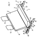
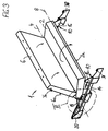
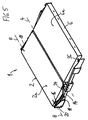
- Figures 1 to 5 each show in schematic perspective views the different Positions of a seat when being transferred from that in FIG. 1 shown use position in that shown in Fig. 5 Not in use or loading position.
- Fig. 6 shows an enlarged view of the area VI in Fig. 3rd
- the seat construction 1 consists of a seat part 2 (seat cushion) and a backrest hinged about a pivot axis 4 6.
- the seat part 2 is on the one hand via a transverse axis 8 foldable out, namely by an angle of about 180 °.
- the seat part 2 - in particular over the transverse axis 8 - connected to a sliding guide 10.
- This articulation and guidance of the seat part 2 is designed such that starting from the use position suitable for sitting (see Fig. 1) by moving and folding of the seat part 2 by approximately 180 ° relative to stationary guide parts and by pivoting the backrest 6 around an angle of about 90 ° relative to the seat part 2 of the entire seat with the backrest 6 and the seat part 2 in the non-use position illustrated in FIG. 5 is transferable, with the seat part 2 and the backrest 6 each with their lower and rear backs 2a and 6a essentially in a common loading level lie.
- the sliding guide 10 consists of two lateral, to each other parallel guide rails 14 which within the Vehicle stationary and essentially approximately horizontal and are arranged parallel to the longitudinal axis of the vehicle. With everyone Guide rail 14, a guide carriage 16 is slidable connected, the guide carriage 16 in the Side areas about the transverse axis 8 with pivoting the seat part 2 are connected. The one about leadership 12 guided area of the seat part 2 with the backrest 6 connecting pivot axis 4 is in both positions (s.
- the guide means 12 are preferably by two lateral Swivel lever 18 formed, the one end in the area of Pivot axis 4, in particular coaxial to this, and articulated at other ends on stationary bearing elements 20 are.
- the bearing elements 20 are in one area arranged in the use position on the the seat part 2 opposite side (behind) the backrest 6 or in the non-use position in the area of the seat part 2 or in the vicinity of the guide carriage 16. Because of the design of the guide means as a pivot lever 18 thus leads the area of the pivot axis 4 during the transfer movement a circular arc movement up and back down again.
- the are of length and shape of the pivot lever 18 determined radius of the circular arc movement and coordinated the position of the hinge points so that a forced movement with the smallest possible space requirement is achieved.
- Locking means for locking are expedient of seat part 2 and backrest 6 in their two different Positions provided. On the one hand it is about locking means not recognizable in the drawing, the in a joint 22 forming the pivot axis 4 (see Fig. 6) arranged between the seat part 2 and the backrest 6 are. These locking means are used in a manner known per se Way for releasably locking the backrest 6 in one certain or adjustable angle (variable backrest angle) relative to the seat part 2 in the use position. By unlocking this locking means can then fold the backrest 6 relative to the seat part 2.
- Bolt-like locking elements are also used as locking means 24 provided, namely on a rocker-like Section 26 extending beyond the pivot axis 4 the backrest 6. Reference is made in particular to FIG. 6. These locking elements 24 engage in the use position in slot-like bolt openings 28 from stationary Abutments 30 a.
- the slot shape of the bolt openings 28 is designed relative to the locking elements 24 so that when pivoting the backrest 6 backwards, the locking elements 24 automatically on a circular path in the corresponding engage shaped bolt openings 28. A release this lock is therefore by folding forward the backrest 6 in the direction of the arrow 32 according to FIG. 6 possible.
- the backrest 6 in their upper, i.e. lying away from the pivot axis 4 End region of lateral, bolt-like locking elements 36 on in the non-use position (see. Fig. 4 and 5) in slot-like bolt openings 38 in the front, stationary Engage the end region of the guide rails 14.
- the locking elements 36 in the Backrest 6 is retractable and in particular for actuation interact with a headrest bracket in such a way that with the headrest 40 mounted, the locking elements 36 held in its lowered position (Fig. 1) and by Disassembly of the headrest 40 automatically in their side projecting, ready-to-lock position are released.
- This Measure is advantageous for security reasons, because in the Use position Risk of accident and injury from laterally protruding parts can be avoided. Also have to anyway before transferring to the non-use position the headrests 40 are removed.
- the invention is not based on the illustrated and described Embodiments limited, but also includes all designs having the same effect in the sense of the invention. Furthermore, the invention is not yet based on the Claim 1 defined combination of features limited, but can also be by any other combination of certain characteristics of all of the individual characteristics disclosed be defined. This means that basically practically every single feature of claim 1 omitted or by at least one elsewhere in the registration disclosed individual feature can be replaced. To that extent is claim 1 only as a first attempt at formulation to understand for an invention.
Abstract
Description
Die vorliegende Erfindung betrifft eine Sitzkonstruktion mit Umklappfunktion, insbesondere für Kfz-Rücksitze, mit einem Sitzteil und einer über eine Schwenkachse klappbar angelenkten Rückenlehne, wobei das Sitzteil derart über eine Querachse umklappbar mit einer Schiebeführung verbunden ist, daß ausgehend von einer zum Sitzen geeigneten Gebrauchsposition durch Verschieben und Umklappen des Sitzteils um etwa 180° relativ zu ortsfesten Führungsteilen sowie durch Verschwenken der Rückenlehne um etwa 90° relativ zum Sitzteil die Rückenlehne und das Sitzteil in eine mit ihren unteren bzw. hinteren Rückseiten im wesentlichen in einer Ebene liegende Nichtgebrauchsposition (Ladeposition) überführbar sind.The present invention relates to a seat construction with folding function, in particular for vehicle rear seats, with a seat part and a foldable over a pivot axis articulated backrest, the seat part so over a transverse axis foldable connected to a sliding guide is that starting from one suitable for sitting Use position by moving and folding the Seat part by about 180 ° relative to stationary guide parts as well as by pivoting the backrest by about 90 ° relative to the seat part the backrest and the seat part in one with their lower and rear backs essentially in-plane non-use position (loading position) are transferable.
Eine derartige Sitzkonstruktion ist einerseits aus der DE-AS 1 286 415 sowie andererseits auch aus der DE 44 22 920 A1 und der parallelen EP 0 689 954 A2 bekannt. Mit diesen bekannten Sitzkonstruktionen ist es möglich, insbesondere zur Schaffung eines vergrößerten Laderaums in einem Fahrzeug den Sitz komplett so umzulegen, daß die Rückenlehne und das Sitzteil jeweils mit ihren Rückseiten im wesentlichen in der Ladeebene liegen. Bei den bekannten Sitzkonstruktionen ist allerdings von Nachteil, daß jeweils praktisch der gesamte Sitz um eine einzige, im vorderen Bereich des Sitzteils angeordnete Querachse verschwenkt werden muß. Dies führt zu einer sehr schwierigen Handhabung, weil beim Umlegen praktisch das Gesamtgewicht von Sitzteil und Rückenlehne manuell bewegt werden muß. Zudem kommt es dabei zu völlig unkoordinierten Bewegungen insbesondere durch die schwenkbeweglich angelenkte Rückenlehne, so daß zum Umlegen auch sehr viel Raum benötigt wird und es auch oft zu Kollisionen mit anderen Teilen innerhalb des Fahrzeugs kommt.Such a seat construction is on the one hand from DE-AS 1 286 415 and on the other hand also from DE 44 22 920 A1 and parallel EP 0 689 954 A2. With these known seat constructions, it is possible, in particular to create an enlarged cargo space in a vehicle completely fold the seat so that the backrest and the seat part with its rear sides essentially lie in the loading level. With the known seat constructions is disadvantageous, however, that each practical the entire seat around a single one, in the front area arranged transverse axis of the seat part must be pivoted. This leads to a very difficult handling, because when Practically fold the total weight of the seat part and Backrest must be moved manually. It also happens to completely uncoordinated movements, especially through the pivoted articulated backrest so that to fold a lot of space is also required and there are often collisions comes with other parts inside the vehicle.
Der vorliegenden Erfindung liegt daher die Aufgabe zugrunde, eine Sitzkonstruktion der genannten Art so zu verbessern, daß die Handhabung wesentlich verbessert und vereinfacht wird.The present invention is therefore based on the object to improve a seat construction of the type mentioned so that the handling is significantly improved and simplified becomes.
Erfindungsgemäß wird dies durch zusätzliche Führungsmittel derart erreicht, daß das Sitzteil und die Rückenlehne während ihrer Überführungsbewegungen zwischen der Gebrauchsposition und der Nichtgebrauchsposition etwa im Bereich der Schwenkachse definiert geführt werden. Hierbei sind die Führungsmittel zudem bevorzugt so ausgebildet, daß der Bereich der Schwenkachse zwischen Sitzteil und Rückenlehne über die Führungsmittel derart über eine definierte Bewegungskurve hinweg bewegbar ist, daß das Überführen von der einen in die andere Position mit einem minimalen Raumbedarf bezüglich der Bewegungsbereiche von Sitzteil und/oder Rückenlehne durchführbar ist. Erfindungsgemäß wird somit praktisch eine zwangsführung geschaffen, wodurch unkoordinierte Bewegungen weitgehend ausgeschlossen sind. Statt dessen führt zumindest das Sitzteil eine exakt definierte Zwangsbewegung beim Überführen von der einen in die andere Position aus. Durch die definierte Führung im Bereich der Schwenkachse kommt es allenfalls im gegenüberliegenden freien Endbereich der Rückenlehne zu undefinierteren Bewegungen, die jedoch auf einen minimalen Bewegungsbereich begrenzt sind. Die erfindungsgemäß zwangsweise definierte Kinematik führt auch insofern zu einer verbesserten Handhabung, als nicht mehr das gesamte Sitzgewicht manuell bewegt werden muß.According to the invention, this is achieved by additional guide means reached such that the seat part and the backrest during their transfer movements between the use position and the non-use position in the area the swivel axis are defined. Here are the Guide means also preferably designed so that the Area of the swivel axis between the seat part and backrest via the guide means in such a way over a defined movement curve is movable away that the transfer of the one in the other position with a minimal space requirement with regard to the range of movement of the seat part and / or Backrest is feasible. According to the invention practically created a forced guidance, which means uncoordinated Movements are largely excluded. Instead of of which at least the seat part leads a precisely defined one Forced movement when moving from one to the other Position off. Through the defined leadership in the area of Swivel axis occurs at most in the opposite free end area of the backrest for undefined movements, which, however, have a minimal range of motion are limited. The one necessarily defined according to the invention Kinematics also leads to improved handling in that than no longer the entire seat weight manually must be moved.
Weitere vorteilhafte Ausgestaltungsmerkmale der Erfindung sind in den Unteransprüchen sowie der folgenden Beschreibung enthalten.Further advantageous design features of the invention are in the subclaims and the following description contain.
Anhand eines in der Zeichnung dargestellten, bevorzugten Ausführungsbeispiels soll die Erfindung nun näher erläutert werden. Dabei zeigen zunächst die Figuren 1 bis 5 jeweils in schematischen Perspektivansichten die verschiedenen Positionen eines Sitzes beim Überführen von der in Fig. 1 dargestellten Gebrauchsposition in die in Fig. 5 dargestellte Nichtgebrauchs- bzw. Ladeposition. Fig. 6 zeigt eine vergrößerte Darstellung des Bereichs VI in Fig. 3.Using a preferred shown in the drawing The invention will now be explained in more detail by way of example become. First, Figures 1 to 5 each show in schematic perspective views the different Positions of a seat when being transferred from that in FIG. 1 shown use position in that shown in Fig. 5 Not in use or loading position. Fig. 6 shows an enlarged view of the area VI in Fig. 3rd
In den Zeichnungsfiguren ist eine erfindungsgemäße Sitzkonstruktion
1 beispielhaft in einer Ausführung als Doppelsitzbank
veranschaulicht. Es sind jedoch auch Ausführungen
als Einzelsitz oder Mehrfachsitzbank möglich. Die Sitzkonstruktion
1 besteht aus einem Sitzteil 2 (Sitzpolster) und
einer über eine Schwenkachse 4 klappbar angelenkten Rückenlehne
6. Das Sitzteil 2 ist einerseits über eine Querachse
8 umklappbar geführt, und zwar um einen Winkel von etwa
180°. Andererseits ist das Sitzteil 2 - insbesondere über
die Querachse 8 - mit einer Schiebeführung 10 verbunden. In the drawing figures there is a seat construction according to the invention
1 as an example in a version as a double seat
illustrated. However, they are also executions
possible as single seat or multiple seat bench. The seat construction
1 consists of a seat part 2 (seat cushion) and
a backrest hinged about a
Diese Anlenkung und Führung des Sitzteils 2 ist derart ausgelegt,
daß ausgehend von der zum Sitzen geeigneten Gebrauchsposition
(s. Fig. 1) durch Verschieben und Umklappen
des Sitzteils 2 um etwa 180° relativ zu ortsfesten Führungsteilen
sowie durch Verschwenken der Rückenlehne 6 um
einen Winkel von etwa 90° relativ zum Sitzteil 2 der
gesamte Sitz mit der Rückenlehne 6 und dem Sitzteil 2 in
die in Fig. 5 veranschaulichte Nichtgebrauchsposition
überführbar ist, wobei dann das Sitzteil 2 und die Rückenlehne
6 jeweils mit ihren unteren bzw. hinteren Rückseiten
2a und 6a im wesentlichen in einer gemeinsamen Ladeebene
liegen. Der Bewegungsablauf zum Überführen von der Gebrauchsstellung
nach Fig.1 in die Nichtgebrauchsstellung
nach Fig. 5 bzw. umgekehrt wird durch die Figuren 1 bis 5
und die eingezeichneten Pfeile deutlich.This articulation and guidance of the
Erfindungsgemäß sind nun zusätzliche Führungsmittel 12 derart
vorgesehen, daß die Sitzkonstruktion 1 - zusätzlich zu
der Führung des Sitzteils 2 über die Querachse 8 und die
Schiebeführung 10 - auch im Bereich der Schwenkachse 4
zwischen Sitzteil 2 und Rückenlehne 6 während ihrer Überführungsbewegungen
stets definiert geführt ist.According to the invention, additional guide means 12 are now such
provided that the seat structure 1 - in addition to
the leadership of the
An dieser Stelle sei bemerkt, daß sich die nachfolgende
Beschreibung auf eine Sitzanordnung bezieht, die in der
Gebrauchsposition in Fahrtrichtung ausgerichtet ist, d.h.
mit dem Sitzteil 2 nach vorne in Fahrtrichtung weist.
Selbstverständlich wäre alternativ dazu auch eine umgekehrte
Ausrichtung entgegen der Fahrtrichtung möglich, so daß
die nachfolgend verwendeten Begriffe "vorne" und "hinten"
durchaus auch ausgetauscht werden können.At this point it should be noted that the following
Description refers to a seating arrangement, which in the
Use position is aligned in the direction of travel, i.e.
with the
Die Schiebeführung 10 besteht aus zwei seitlichen, zueinander
parallelen Führungsschienen 14, die innerhalb des
Fahrzeugs ortsfest und im wesentlichen etwa horizontal und
parallel zur Fahrzeug-Längsachse angeordnet sind. Mit jeder
Führungsschiene 14 ist ein Führungsschlitten 16 verschiebbar
verbunden, wobei die Führungsschlitten 16 in den
Seitenbereichen über die Querachse 8 schwenkbeweglich mit
dem Sitzteil 2 verbunden sind. Der über die Führungsmittel
12 geführte Bereich der das Sitzteil 2 mit der Rückenlehne
6 verbindenden Schwenkachse 4 ist in beiden Positionen (s.
Fig. 1 und 5) von Sitzteil 2 und Rückenlehne 6 in einem
etwa mittigen Bereich der Längserstreckung der Führungsschienen
14 angeordnet und dabei über die erfindungsgemäßen
Führungsmittel 12 derart in einer zu den Führungsschienen
14 im wesentlichen senkrechten, vertikalen Richtung beweglich
geführt, daß sich beim Überführen von der einen in die
andere Position der Bereich der Schwenkachse 4 etwa vertikal
zu den Führungsschienen 14 nach oben wegbewegt, so
daß das Sitzteil 2 unter gleichzeitigem Umlegen um etwa
180° mit den Führungsschlitten 16 längs der Führungsschienen
14 praktisch unter dem dazu angehobenen Bereich der
Schwenkachse 4 hindurch vom vorderen zum hinteren Schienenbereich
bzw. umgekehrt bewegbar ist.The
Die Führungsmittel 12 sind vorzugsweise durch zwei seitliche
Schwenkhebel 18 gebildet, die einendig im Bereich der
Schwenkachse 4, und zwar insbesondere koaxial zu dieser,
sowie anderendig an ortsfesten Lagerelementen 20 angelenkt
sind. Dabei sind die Lagerelemente 20 in einem Bereich
angeordnet, der in der Gebrauchsposition auf der dem Sitzteil
2 entgegengesetzten Seite (hinter) der Rückenlehne 6
bzw. in der Nichtgebrauchsposition im Bereich des Sitzteils
2 bzw. in der Nähe der Führungsschlitten 16 liegt. Aufgrund
der Ausgestaltung der Führungsmittel als Schwenkhebel 18
führt somit der Bereich der Schwenkachse 4 bei der Überführungsbewegung
eine Kreisbogenbewegung nach oben und
wieder zurück nach unten aus. Dabei sind der von der Länge
und Form der Schwenkhebel 18 bestimmte Radius der Kreisbogenbewegung
und die Lage der Gelenkpunkte so abgestimmt,
daß eine Zwangsbewegung mit geringstmöglichem Raumbedarf
erreicht wird.The guide means 12 are preferably by two lateral
Swivel
Zweckmäßigerweise sind Verriegelungsmittel zum Arretieren
von Sitzteil 2 und Rückenlehne 6 in ihren beiden verschiedenen
Positionen vorgesehen. Einerseits handelt es sich um
in der Zeichnung nicht erkennbare Verriegelungsmittel, die
in einem die Schwenkachse 4 bildenden Gelenk 22 (s. hierzu
Fig. 6) zwischen Sitzteil 2 und Rückenlehne 6 angeordnet
sind. Diese Verriegelungsmittel dienen in an sich bekannter
Weise zum lösbaren Arretieren der Rückenlehne 6 in einem
bestimmten oder einstellbaren Winkel (variable Lehnenneigung)
relativ zum Sitzteil 2 in der Gebrauchsposition.
Durch Entriegeln dieser Verriegelungsmittel läßt sich dann
die Rückenlehne 6 relativ zum Sitzteil 2 umlegen.Locking means for locking are expedient
of
Als Verriegelungsmittel sind ferner bolzenartige Riegelelemente
24 vorgesehen, und zwar an einem sich wippenartig
über die Schwenkachse 4 hinaus erstreckenden Abschnitt 26
der Rückenlehne 6. Hierzu wird insbesondere auf Fig. 6 verwiesen.
Diese Riegelelemente 24 greifen in der Gebrauchsposition
in schlitzartige Riegelöffnungen 28 von ortsfesten
Widerlagern 30 ein. Die Schlitzform der Riegelöffnungen 28
ist relativ zu den Riegelelementen 24 so ausgebildet, daß
beim nach hinten Verschwenken der Rückenlehne 6 die Riegelelemente
24 selbsttätig auf einer Kreisbahn in die entsprechend
geformten Riegelöffnungen 28 eingreifen. Ein Lösen
dieser Verriegelung ist demzufolge durch nach vorne umklappen
der Rückenlehne 6 in Pfeilrichtung 32 gemäß Fig. 6
möglich.Bolt-like locking elements are also used as locking means
24 provided, namely on a rocker-
Wie sich aus Fig. 5 ergibt, liegen die Riegelelemente 24 in
der Nichtgebrauchsstellung in Lagerausnehmungen 34 der
Widerlager 30. Die Lagerausnehmungen 34 liegen dabei in
Verstellrichtung versetzt zu den Riegelöffnungen 28.5, the
Als weitere Verriegelungsmittel weist die Rückenlehne 6 in
ihrem oberen, d.h. von der Schwenkachse 4 entfernt liegenden
Endbereich seitliche, bolzenartige Riegelelemente 36
auf, die in der Nichtgebrauchsstellung (s. Fig. 4 und 5) in
schlitzartige Riegelöffnungen 38 im vorderen, ortsfesten
Endbereich der Führungsschienen 14 eingreifen. Hierbei ist
es besonders vorteilhaft, wenn die Riegelelemente 36 in der
Rückenlehne 6 versenkbar gelagert und zur Betätigung insbesondere
mit einer Kopfstützenhalterung derart zusammenwirken,
daß bei montierter Kopfstütze 40 die Riegelelemente
36 in ihrer versenkten Stellung gehalten (Fig. 1) und durch
Demontage der Kopfstütze 40 selbsttätig in ihre seitlich
vorspringende, riegelbereite Lage freigegeben werden. Diese
Maßnahme ist aus Sicherheitsgründen von Vorteil, da in der
Gebrauchsposition Unfall- und Verletzungsgefahren durch
seitlich vorspringende Teile vermieden werden. Zudem müssen
ohnehin vor dem Überführen in die Nichtgebrauchsposition
die Kopfstützen 40 entfernt werden.As a further locking means, the
In einer weiteren vorteilhaften Ausgestaltung der Erfindung
ist mindestens ein Federelement oder dergleichen motorischer
Kraftantrieb zur Unterstützung des Bewegungsablaufs
beim Überführen zwischen den Gebrauchs- und Nichtgebrauchspositionen
vorgesehen. Hierbei kann es sich beispielsweise
um mindestens eine Gasdruckfeder handeln, die z.B. an einem
in den Zeichnungsfiguren erkennbaren Lagerelement 42 mindestens
eines der beiden Schwenkhebel 18 angreifen kann.
Hierdurch wird ein besonders guter Bedienungskomfort erreicht,
indem die Sitzkonstruktion 1 nach dem Entriegeln
praktisch selbsttätig im Bereich der Schwenkachse 4 nach
oben gedrückt wird.In a further advantageous embodiment of the invention
is at least one spring element or the like motor
Power drive to support the movement
when transferring between the use and non-use positions
intended. This can be, for example
are at least one gas pressure spring, e.g. on one
bearing
Die Erfindung ist nicht auf die dargestellten und beschriebenen Ausführungsbeispiele beschränkt, sondern umfaßt auch alle im Sinne der Erfindung gleichwirkenden Ausführungen. Ferner ist die Erfindung bislang auch noch nicht auf die im Anspruch 1 definierte Merkmalskombination beschränkt, sondern kann auch durch jede beliebige andere Kombination von bestimmten Merkmalen aller insgesamt offenbarten Einzelmerkmalen definiert sein. Dies bedeutet, daß grundsätzlich praktisch jedes Einzelmerkmal des Anspruchs 1 weggelassen bzw. durch mindestens ein an anderer Stelle der Anmeldung offenbartes Einzelmerkmal ersetzt werden kann. Insofern ist der Anspruch 1 lediglich als ein erster Formulierungsversuch für eine Erfindung zu verstehen.The invention is not based on the illustrated and described Embodiments limited, but also includes all designs having the same effect in the sense of the invention. Furthermore, the invention is not yet based on the Claim 1 defined combination of features limited, but can also be by any other combination of certain characteristics of all of the individual characteristics disclosed be defined. This means that basically practically every single feature of claim 1 omitted or by at least one elsewhere in the registration disclosed individual feature can be replaced. To that extent is claim 1 only as a first attempt at formulation to understand for an invention.
Claims (12)
gekennzeichnet durch zusätzliche Führungsmittel (12) derart, daß das Sitzteil (2) und die Rückenlehne (6) während ihrer Überführungsbewegungen zwischen der Gebrauchsposition und der Nichtgebrauchsposition etwa im Bereich der Schwenkachse (4) definiert geführt werden. Seat construction (1) with a folding function, in particular for motor vehicle rear seats, with a seat part (2) and a backrest (6) hinged about a pivot axis (4), whereby the seat part (2) can be folded over with a transverse axis (8) Sliding guide (10) is connected that starting from a position suitable for sitting by moving and folding the seat part (2) by about 180 ° relative to stationary guide parts and by pivoting the backrest (6) by about 90 ° relative to the seat part (2) the backrest (6) and the seat part (2) can be converted into a non-use position lying essentially in one plane with their lower or rear rear sides (2a, 6a),
characterized by additional guide means (12) such that the seat part (2) and the backrest (6) are guided in a defined manner during their transfer movements between the use position and the non-use position approximately in the region of the pivot axis (4).
dadurch gekennzeichnet, daß der Bereich der Schwenkachse (4) über die Führungsmittel (12) derart über eine definierte Bewegungskurve hinweg bewegbar ist, daß das Überführen von der einen in die andere Position mit einem minimalen Raumbedarf bezüglich der Bewegungsbereiche von Sitzteil (2) und/oder Rückenlehne (6) durchführbar ist.Seat construction according to claim 1,
characterized in that the region of the pivot axis (4) can be moved over a defined movement curve over the guide means (12) in such a way that the transfer from one position to the other with a minimal space requirement with regard to the movement regions of the seat part (2) and / or backrest (6) can be carried out.
dadurch gekennzeichnet, daß die Schiebeführung (10) aus ortsfesten, im wesentlichen etwa horizontalen Führungsschienen (14) sowie mit dem Sitzteil (2) über die Querachse (8) verbundenen Führungsschlitten (16) besteht, wobei der Bereich der Schwenkachse (4) in beiden Positionen von Sitzteil (2) und Rückenlehne (6) in einem etwa mittigen Bereich der Führungsschienen (16) angeordnet und über die Führungsmittel (12) derart im wesentlichen senkrecht zu den Führungsschienen (14) beweglich ist, daß sich beim Überführen der Bereich der Schwenkachse (4) von den Führungsschienen (14) etwa vertikal wegbewegt und das Sitzteil (2) unter gleichzeitigem Umlegen um etwa 180° mit dem Führungsschlitten (16) längs der Führungsschienen (14) bewegbar ist.Seat construction according to claim 1 or 2,
characterized in that the sliding guide (10) consists of stationary, essentially approximately horizontal guide rails (14) and guide carriages (16) connected to the seat part (2) via the transverse axis (8), the region of the pivot axis (4) in both Positions of the seat part (2) and backrest (6) are arranged in an approximately central region of the guide rails (16) and can be moved essentially perpendicularly to the guide rails (14) via the guide means (12) in such a way that the region of the pivot axis moves when being transferred (4) moved approximately vertically away from the guide rails (14) and the seat part (2) can be moved along the guide rails (14) with the guide carriage (16) while being folded over by about 180 °.
dadurch gekennzeichnet, daß die Lagerelemente (20) in einem Bereich angeordnet sind, der in der Gebrauchsposition auf der dem Sitzteil (2) entgegengesetzten Seite der Rückenlehne (6) bzw. in der Nichtgebrauchsposition im Bereich des Sitzteils (2) liegt.Seat construction according to claim 4,
characterized in that the bearing elements (20) are arranged in an area which, in the use position, lies on the side of the backrest (6) opposite the seat part (2) or in the non-use position in the area of the seat part (2).
dadurch gekenzeichnet, daß die Rückenlehne (6) an einem sich wippenartig über die Schwenkachse (4) hinaus erstreckenden Abschnitt (26) bolzenartige Riegelelemente (24) aufweist, die in der Gebrauchsposition in schlitzartige Riegelöffnungen (28) von ortsfesten Widerlagern (30) eingreifen.Seat construction according to claim 6 or 7,
characterized in that the backrest (6) on a section (26) which extends like a rocker beyond the pivot axis (4) has bolt-like locking elements (24) which, in the position of use, engage in slot-like locking openings (28) of stationary abutments (30).
dadurch gekennzeichnet, daß die Riegelelemente (24) in der Nichtgebrauchsstellung in Lagerausnehmungen (34) der Widerlager (30) liegen. Seat construction according to claim 8,
characterized in that the locking elements (24) lie in the non-use position in bearing recesses (34) of the abutment (30).
dadurch gekennzeichnet, daß die Riegelelemente (36) in der Rückenlehne (6) versenkbar gelagert und zur Betätigung insbesondere mit einer Kopfstützenhalterung derart zusammenwirken, daß bei montierter Kopfstütze (40) die Riegelelemente (36) in ihrer versenkten Stellung gehalten und durch Demontage der Kopfstütze (40) selbsttätig in ihre seitlich vorspringende, riegelbereite Lage freigegeben werden.Seat construction according to claim 10,
characterized in that the locking elements (36) are seated in the backrest (6) so that they can be actuated and in particular interact with a headrest holder such that when the headrest (40) is mounted the locking elements (36) are held in their lowered position and by removing the headrest ( 40) are released automatically into their laterally projecting, ready-to-lock position.
Applications Claiming Priority (2)
| Application Number | Priority Date | Filing Date | Title |
|---|---|---|---|
| DE29810326U | 1998-06-09 | ||
| DE29810326U DE29810326U1 (en) | 1998-06-09 | 1998-06-09 | Seat construction with folding function for car seats |
Publications (2)
| Publication Number | Publication Date |
|---|---|
| EP0970843A1 true EP0970843A1 (en) | 2000-01-12 |
| EP0970843B1 EP0970843B1 (en) | 2004-04-14 |
Family
ID=8058306
Family Applications (1)
| Application Number | Title | Priority Date | Filing Date |
|---|---|---|---|
| EP99110986A Expired - Lifetime EP0970843B1 (en) | 1998-06-09 | 1999-06-09 | Seat structure with folding function for automotive seat |
Country Status (2)
| Country | Link |
|---|---|
| EP (1) | EP0970843B1 (en) |
| DE (2) | DE29810326U1 (en) |
Families Citing this family (5)
| Publication number | Priority date | Publication date | Assignee | Title |
|---|---|---|---|---|
| DE102004005969B4 (en) * | 2004-02-06 | 2014-01-09 | GM Global Technology Operations LLC (n. d. Ges. d. Staates Delaware) | Seat |
| DE102004041734B3 (en) * | 2004-08-28 | 2006-01-05 | Keiper Gmbh & Co.Kg | Seat for motor vehicle has a backrest movable to floor position by pushing in longitudinal direction |
| DE102009023014A1 (en) | 2009-05-28 | 2010-12-02 | Kiekert Ag | Vehicle seat i.e. motor vehicle seat, has backrest hinged to seat part in folding manner, and tightening device holding locking gear and locking bracket that are mutually in contact with drive |
| DE102013002810A1 (en) | 2013-02-19 | 2014-08-21 | GM Global Technology Operations LLC (n. d. Gesetzen des Staates Delaware) | Vehicle has rear seat assembly comprising control unit for pivoting of backrest about pivot axis between seat and loading position |
| DE102013012604A1 (en) | 2013-07-29 | 2015-01-29 | GM Global Technology Operations LLC (n. d. Gesetzen des Staates Delaware) | Vehicle with a rear seat arrangement |
Citations (4)
| Publication number | Priority date | Publication date | Assignee | Title |
|---|---|---|---|---|
| US3171682A (en) * | 1963-09-23 | 1965-03-02 | Gen Motors Corp | Folding vehicle seats |
| DE1286415B (en) * | 1965-10-15 | 1969-01-02 | Hans Glas Gmbh Isaria Maschine | Loading area for vehicles, in particular motor vehicles, which can be converted into one or more bench seats |
| GB2009592A (en) * | 1977-12-09 | 1979-06-20 | Peugeot | Convertible seat for automobile vehicles |
| EP0689954A2 (en) * | 1994-06-30 | 1996-01-03 | Adam Opel Ag | Seat arrangement, especially for the load or passenger compartment of a motor vehicle |
-
1998
- 1998-06-09 DE DE29810326U patent/DE29810326U1/en not_active Expired - Lifetime
-
1999
- 1999-06-09 DE DE59909146T patent/DE59909146D1/en not_active Expired - Fee Related
- 1999-06-09 EP EP99110986A patent/EP0970843B1/en not_active Expired - Lifetime
Patent Citations (4)
| Publication number | Priority date | Publication date | Assignee | Title |
|---|---|---|---|---|
| US3171682A (en) * | 1963-09-23 | 1965-03-02 | Gen Motors Corp | Folding vehicle seats |
| DE1286415B (en) * | 1965-10-15 | 1969-01-02 | Hans Glas Gmbh Isaria Maschine | Loading area for vehicles, in particular motor vehicles, which can be converted into one or more bench seats |
| GB2009592A (en) * | 1977-12-09 | 1979-06-20 | Peugeot | Convertible seat for automobile vehicles |
| EP0689954A2 (en) * | 1994-06-30 | 1996-01-03 | Adam Opel Ag | Seat arrangement, especially for the load or passenger compartment of a motor vehicle |
Also Published As
| Publication number | Publication date |
|---|---|
| DE59909146D1 (en) | 2004-05-19 |
| DE29810326U1 (en) | 1999-10-14 |
| EP0970843B1 (en) | 2004-04-14 |
Similar Documents
| Publication | Publication Date | Title |
|---|---|---|
| DE102014107816B4 (en) | Commercial vehicle seat with lockable cross-slide part | |
| DE102009037816B3 (en) | Vehicle seat, in particular motor vehicle seat | |
| EP2001708B1 (en) | Releasing device for a table part of a seat system for passenger vehicles | |
| DE19730131C2 (en) | Rotatable and slidable vehicle seat | |
| WO2019096774A2 (en) | Easy-entry vehicle seat | |
| EP3092151A1 (en) | Vehicle seat | |
| EP2736762B1 (en) | Vehicle seat, in particular motor vehicle seat | |
| DE102012112525A1 (en) | Commercial vehicle seat with Doppelarretierbarem cross slide part | |
| DE102008017707A1 (en) | Motor vehicle seat with prestressed wing rest and seat arrangement with such a motor vehicle seat | |
| EP0970844A1 (en) | Seat module | |
| WO2014083051A1 (en) | Vehicle seat | |
| DE10012590B4 (en) | Seat arrangement arranged in front of a loading space of a motor vehicle | |
| DE3237214A1 (en) | DEVICE FOR CHANGING THE ORIENTATION OF A PUSHBODY ASSEMBLY OF A PRINTER | |
| EP1762488B1 (en) | Seat system with table unit for passenger transport vehicles, in particular for aircraft | |
| DE3404612A1 (en) | HEADREST OF A VEHICLE SEAT WITH TWO CARRIAGE BRACKETS ATTACHED TO THE SEATREST | |
| WO2006079300A2 (en) | Backrest unit for a motor vehicle seat | |
| DE3329725C2 (en) | ||
| EP2481629A2 (en) | Vehicle seat with securing means for a support element | |
| EP0970843B1 (en) | Seat structure with folding function for automotive seat | |
| DE10145240B4 (en) | Headrest for vehicle seats | |
| EP0433317B1 (en) | Child's safety seat | |
| WO2014125055A1 (en) | Vehicle seat, in particular for a rear row of seats | |
| DE202007018960U1 (en) | Stowable vehicle seat | |
| DE19919698A1 (en) | Vehicle seat, in particular motor vehicle seat | |
| WO2005016752A1 (en) | Table unit for vehicle seats |
Legal Events
| Date | Code | Title | Description |
|---|---|---|---|
| PUAI | Public reference made under article 153(3) epc to a published international application that has entered the european phase |
Free format text: ORIGINAL CODE: 0009012 |
|
| AK | Designated contracting states |
Kind code of ref document: A1 Designated state(s): DE FR GB IT |
|
| AX | Request for extension of the european patent |
Free format text: AL;LT;LV;MK;RO;SI |
|
| EL | Fr: translation of claims filed | ||
| GBC | Gb: translation of claims filed (gb section 78(7)/1977) | ||
| 17P | Request for examination filed |
Effective date: 20000610 |
|
| AKX | Designation fees paid |
Free format text: DE FR GB IT |
|
| GRAP | Despatch of communication of intention to grant a patent |
Free format text: ORIGINAL CODE: EPIDOSNIGR1 |
|
| GRAS | Grant fee paid |
Free format text: ORIGINAL CODE: EPIDOSNIGR3 |
|
| GRAA | (expected) grant |
Free format text: ORIGINAL CODE: 0009210 |
|
| AK | Designated contracting states |
Kind code of ref document: B1 Designated state(s): DE FR GB IT |
|
| REG | Reference to a national code |
Ref country code: GB Ref legal event code: FG4D Free format text: NOT ENGLISH |
|
| REF | Corresponds to: |
Ref document number: 59909146 Country of ref document: DE Date of ref document: 20040519 Kind code of ref document: P |
|
| GBT | Gb: translation of ep patent filed (gb section 77(6)(a)/1977) |
Effective date: 20040723 |
|
| ET | Fr: translation filed | ||
| PLBE | No opposition filed within time limit |
Free format text: ORIGINAL CODE: 0009261 |
|
| STAA | Information on the status of an ep patent application or granted ep patent |
Free format text: STATUS: NO OPPOSITION FILED WITHIN TIME LIMIT |
|
| 26N | No opposition filed |
Effective date: 20050117 |
|
| PGFP | Annual fee paid to national office [announced via postgrant information from national office to epo] |
Ref country code: IT Payment date: 20080529 Year of fee payment: 10 |
|
| PGFP | Annual fee paid to national office [announced via postgrant information from national office to epo] |
Ref country code: DE Payment date: 20080630 Year of fee payment: 10 |
|
| PGFP | Annual fee paid to national office [announced via postgrant information from national office to epo] |
Ref country code: GB Payment date: 20080521 Year of fee payment: 10 |
|
| GBPC | Gb: european patent ceased through non-payment of renewal fee |
Effective date: 20090609 |
|
| REG | Reference to a national code |
Ref country code: FR Ref legal event code: ST Effective date: 20100226 |
|
| PG25 | Lapsed in a contracting state [announced via postgrant information from national office to epo] |
Ref country code: FR Free format text: LAPSE BECAUSE OF NON-PAYMENT OF DUE FEES Effective date: 20090630 |
|
| PGFP | Annual fee paid to national office [announced via postgrant information from national office to epo] |
Ref country code: FR Payment date: 20080513 Year of fee payment: 10 |
|
| PG25 | Lapsed in a contracting state [announced via postgrant information from national office to epo] |
Ref country code: GB Free format text: LAPSE BECAUSE OF NON-PAYMENT OF DUE FEES Effective date: 20090609 |
|
| PG25 | Lapsed in a contracting state [announced via postgrant information from national office to epo] |
Ref country code: DE Free format text: LAPSE BECAUSE OF NON-PAYMENT OF DUE FEES Effective date: 20100101 |
|
| PG25 | Lapsed in a contracting state [announced via postgrant information from national office to epo] |
Ref country code: IT Free format text: LAPSE BECAUSE OF NON-PAYMENT OF DUE FEES Effective date: 20090609 |