EP0433317B1 - Child's safety seat - Google Patents
Child's safety seat Download PDFInfo
- Publication number
- EP0433317B1 EP0433317B1 EP89909713A EP89909713A EP0433317B1 EP 0433317 B1 EP0433317 B1 EP 0433317B1 EP 89909713 A EP89909713 A EP 89909713A EP 89909713 A EP89909713 A EP 89909713A EP 0433317 B1 EP0433317 B1 EP 0433317B1
- Authority
- EP
- European Patent Office
- Prior art keywords
- child safety
- lever
- safety seat
- seat according
- seat
- Prior art date
- Legal status (The legal status is an assumption and is not a legal conclusion. Google has not performed a legal analysis and makes no representation as to the accuracy of the status listed.)
- Expired - Lifetime
Links
Images


Classifications
-
- B—PERFORMING OPERATIONS; TRANSPORTING
- B60—VEHICLES IN GENERAL
- B60N—SEATS SPECIALLY ADAPTED FOR VEHICLES; VEHICLE PASSENGER ACCOMMODATION NOT OTHERWISE PROVIDED FOR
- B60N2/00—Seats specially adapted for vehicles; Arrangement or mounting of seats in vehicles
- B60N2/24—Seats specially adapted for vehicles; Arrangement or mounting of seats in vehicles for particular purposes or particular vehicles
- B60N2/26—Seats specially adapted for vehicles; Arrangement or mounting of seats in vehicles for particular purposes or particular vehicles for children
- B60N2/28—Seats readily mountable on, and dismountable from, existing seats or other parts of the vehicle
- B60N2/2857—Seats readily mountable on, and dismountable from, existing seats or other parts of the vehicle characterised by the peculiar orientation of the child
- B60N2/286—Seats readily mountable on, and dismountable from, existing seats or other parts of the vehicle characterised by the peculiar orientation of the child forward facing
-
- B—PERFORMING OPERATIONS; TRANSPORTING
- B60—VEHICLES IN GENERAL
- B60N—SEATS SPECIALLY ADAPTED FOR VEHICLES; VEHICLE PASSENGER ACCOMMODATION NOT OTHERWISE PROVIDED FOR
- B60N2/00—Seats specially adapted for vehicles; Arrangement or mounting of seats in vehicles
- B60N2/24—Seats specially adapted for vehicles; Arrangement or mounting of seats in vehicles for particular purposes or particular vehicles
- B60N2/26—Seats specially adapted for vehicles; Arrangement or mounting of seats in vehicles for particular purposes or particular vehicles for children
- B60N2/28—Seats readily mountable on, and dismountable from, existing seats or other parts of the vehicle
- B60N2/2821—Seats readily mountable on, and dismountable from, existing seats or other parts of the vehicle having a seat and a base part
-
- B—PERFORMING OPERATIONS; TRANSPORTING
- B60—VEHICLES IN GENERAL
- B60N—SEATS SPECIALLY ADAPTED FOR VEHICLES; VEHICLE PASSENGER ACCOMMODATION NOT OTHERWISE PROVIDED FOR
- B60N2/00—Seats specially adapted for vehicles; Arrangement or mounting of seats in vehicles
- B60N2/24—Seats specially adapted for vehicles; Arrangement or mounting of seats in vehicles for particular purposes or particular vehicles
- B60N2/26—Seats specially adapted for vehicles; Arrangement or mounting of seats in vehicles for particular purposes or particular vehicles for children
- B60N2/28—Seats readily mountable on, and dismountable from, existing seats or other parts of the vehicle
- B60N2/2875—Seats readily mountable on, and dismountable from, existing seats or other parts of the vehicle inclinable, as a whole or partially
Definitions
- the invention relates to a child safety seat according to the preamble of claim 1.
- a child safety seat of this type is known from FR-A-2 553 985.
- the upper rear edge of the bucket seat also performs an approximately vertical or approximately along the backrest of a motor vehicle seat when the seat is pivoted.
- the seat is only placed with its support on the motor vehicle seat, without being secured there against slipping or tilting.
- the present invention has for its object to develop a child seat of the above type so that it is secured against slipping on its support and / or against tilting and that a move of the seat from a sitting to a lying position and vice versa is possible in a simple manner is.
- this object is achieved by the features specified in the characterizing part of claim 1.
- This design ensures that the bucket seat lies cleanly against the backrest of the motor vehicle with the backrest in every operating position.
- the actuating mechanism is integrated in the bucket seat. It has proven to be useful if the bucket seat on its underside or preferably if the support on its top contains at least one, preferably two, substantially flat sliding surfaces which run in the direction of displacement and along which the bucket seat is displaceable.
- the support is preferably designed as a platform that can be set up on the seating area of a motor vehicle seat and that contains flat areas or guides on its surface, or it is formed by a frame that contains two longitudinal and running rails that are held at a fixed distance from one another. The support holds the bucket seat in such a way that it remains longitudinally displaceable relative to the same, but cannot be lifted upwards.
- At least one bracket extending substantially in the direction of the longitudinal displacement is arranged, under which a holding element attached to the support or to the bucket seat engages in such a way that the Bracket can also set the end positions for the forward and backward displacement of the bucket seat.
- the at least one first lever is articulated on the lateral edge region of the support.
- a lever is expediently attached to both sides of the support, at least one of which is operatively connected to the actuating mechanism, the lever advantageously being symmetrical to the longitudinal center plane of the bucket seat are arranged.
- the two levers are formed by a U-shaped bracket, the free legs of which are rotatably articulated on the bucket seat, the bracket being pivotably mounted in the region of the part connecting the free ends substantially parallel to the rear edge of the support and along the same.
- the child safety seat is transferred from the sitting to the lying position and vice versa in a simple sequence of movements.
- the underside of the bucket seat is bent upwards in the rear area.
- the flat underside and the substantially flat backrest of the bucket seat do not abut one another directly at the preselected angle, but are connected to one another by a bevelled area which runs parallel to the top of the support when the sleeping position is taken, while when the child safety seat is on
- the front area of the bucket seat, which forms the flat underside of it, runs parallel to the top of the support.
- the effort required for the adjustment can be reduced if at least one roller is provided on the top of the support or preferably on the underside of the bucket seat, by means of which the bucket seat is supported on the support, the at least one role in front of the articulation point of the first lever arranged on the pad is.
- This configuration also makes it possible to keep the manufacturing tolerances in the individual parts of the child safety seat lower than would be possible with a pure sliding guide.
- the at least one roller is preferably arranged on the underside of the bucket seat in the area of the front bend in such a way that the underside of the front area of the bucket seat almost rests on the support when the child safety seat assumes its seating position.
- a roller is provided on the underside of the bucket seat at the ends of an axis running transversely to the seat center plane, the axis running under the bracket, so that at the same time it limits the positions of the end displacement and prevents the bucket seat, especially in the event of an accident, is lifted off the circulation in the vehicle.
- the first lever is designed as a one-armed lever.
- the adjustment mechanism contains a second lever, one end of which is articulated to the first lever and the other end of which engages with an eccentric which can be pivoted about an axis of rotation.
- the articulation point of the second lever on the first lever preferably takes place adjacent to its articulation point on the bucket seat, namely between this articulation point of the first lever on Bucket seat and its pivot point on the support.
- the existence that the articulation point of the second lever on the first lever has from the articulation point of the first lever on the bucket seat is preferably 1/10 to 1/9 of the distance between the articulation points of the first lever on the bucket seat and on the support.
- the articulation point of the second lever on the first lever is preferably offset laterally to the straight line connecting the articulation points of the first lever.
- the end of the second lever which is in engagement with the eccentric is expediently guided in a longitudinal guide which extends radially to the fulcrum of the eccentric.
- This measure and a suitable choice of the length of the lever, the position of the pivot point of the second lever on the first lever, and the course of the eccentric means that the axis of rotation of the eccentric and the two pivot points of the second lever are at least in one of the two end positions Straight lines lie, which in these end positions causes self-locking, which counteracts an unintentional adjustment of the child safety seat.
- the eccentric is preferably formed by an eccentric disc with a guide slot, in which a pivot is guided, which forms the one articulation point of the second lever, and is positively guided in the longitudinal guide.
- the adjusting mechanism contains a sleeve which is pivotably articulated on the first lever and which receives an area of an adjusting spindle provided with an external thread via an internal thread.
- the sleeve is advantageously rotatably mounted on the first lever about an axis running perpendicular to its longitudinal axis, the axis of rotation preferably being aligned parallel to the articulation axis of the first lever on the bucket seat.
- This fastening of the sleeve to the first lever is expediently carried out between its two articulation points, preferably close to the articulation point of the first lever on the bucket seat, specifically between the two articulation points of this lever.
- this has an actuation which contains an adjusting member which can be operated from the front of the child safety seat.
- the actuation for the adjusting spindle contains an adjusting member which can be operated from the side wall of the child safety seat.
- the actuating mechanism for the first lever is arranged in the side region of the bucket seat, preferably in the base region and / or in one of the armrests of a seat shell, since there is sufficient construction space available there.
- the mechanics covered in this way avoid any risk of injury to the children being transported.
- this enables simple assembly, since the seat shell only has to be provided with an appropriate cavity and can then be put over the construction.
- the bucket seat contains a frame which receives the actual seat shell and on which the actuating mechanism is mounted and the first lever is articulated.
- the seat shell is preferably made in a manner known per se from a foamed plastic, which is usually provided with a seat cover. Since it is a matter of known constructions, this application will not be dealt with in more detail in this application.
- the frame contains an O-ring-shaped frame with preferably straight upper and lower sides, which come to lie at the head or foot end of the child safety seat, and with side areas which are essentially perpendicular to the upper - And underside trending levels are arranged.
- the O-ring-shaped frame is expediently bent at least twice in its side areas.
- the part of the side areas adjoining the underside of the frame, when the bucket seat is installed and when it occupies the seat position runs along the bottom of the seat shell and parallel to the surface of the support. This area is adjoined by a first bend, which forms an acute angle with the rearward extension of the first area.
- transition parts go over the second bend into the upper parts of the side areas, which, following the backrest of the seat shell, form the back of the bucket seat.
- the second turn lies approximately above the articulation point of the first lever on the support.
- it is particularly favorable if it is designed as a tubular frame.
- the frame expediently holds in the region of its first bend, and expediently just behind it, the axis of rotation for the rollers, which, as already mentioned above, preferably passes under the bracket attached to the top of the support.
- an eyelet-shaped guide bracket into which the belt strap can be inserted, is arranged on the frame in the area of an upper cross bar and at least in the side area below the same.
- the eyelet-shaped guide brackets are expediently formed by two overlapping, freely projecting bracket parts, of which the free end of one is bent over the free end of the other, so that the belt strap is protected against possible injuries.
- a retaining element is also provided, into which the lap belt part of a seat belt can be inserted, so that this also helps to hold the child safety seat firmly on the seat of the motor vehicle.
- the retaining element is preferably fastened to the support or to the at least one first lever, in the latter case the fastening advantageously being carried out on the cross strut which connects the first lever attached to the right and left of the bucket seat, and the axis of rotation of the levers for their articulation forms on the pad.
- the retaining element is expediently designed as a U-shaped bracket which is held with both U-legs, its freely projecting region being bent back in a hook shape.
- the detachable bracket is preferably provided on the frame itself.
- the children are secured in the seat shell in accordance with a preferred embodiment of the child safety seat by means of a harness belt, the shoulder belt straps of which are preferably attached to a cross strut of the frame and / or the lap belt straps are preferably fastened to the axis of rotation of the rollers and the belt straps are slotted in the seat shell lead out at the front.
- the easiest way to attach the lap belt straps is to put a piece of belt strap around the axis of rotation of the rollers, the free ends being provided with a lock element which forms the right and left ends of the lap belt straps.
- a further detachable holder for the oblique shoulder belt of the 3-point seat belt is advantageously provided in the lower region in order to prevent the child seat held by the oblique shoulder belt in the region of its upper edge from tipping up in the event of an impact.
- the shoulder straps of the harness belt system are attached to the same cross strut as the diagonal shoulder strap of the 3-point seat belt, the strength of the holding forces is optimally transferred from the 3-point seat belt system of the motor vehicle to the harness belt system of the child safety seat.
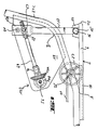
- FIG. 1 shows an overall perspective view of a frame for a child safety seat, in which, for reasons of clarity, only the seat shell, for example made of plastic foam and placed on the frame, is omitted.
- FIG. 2 shows a front view of the child safety seat according to FIG. 1 with a schematically indicated child.
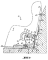
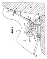
- FIG 3 shows a side view of a first functional position of the child safety seat, in which the child occupies the sitting position.
- Fig. 4 shows a second functional position of the child safety seat in side view, in which it assumes the rest position.
- FIG. 5 and 6 show a first variant of the belt fastening on the back part of the seat frame in a view from the rear, and a section along the line VI-VI in FIG. 5.
- FIGS. 7 and 8 show a second variant of the belt fastening in the same representation as in FIGS. 5 and 6.
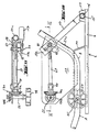
- FIG. 9 and 10 show two detailed side views of a second embodiment of the adjustment mechanism, with FIG. 9 showing a first functional position in which the child safety seat occupies the seat position, and FIG. 10 representing a second functional position in which the child safety seat is in the rest position.
- FIG. 11 shows a section along the line XI-XI in FIG. 10.
- FIG. 1 The drawings show a child safety seat 1, which consists of a support 2 and a bucket seat 3, the latter being formed by a frame 4 and a seat shell 5 held by the frame 4, which in the usual way and as indicated schematically in FIG. 2, the child picks up and holds.
- a child safety seat 1 which consists of a support 2 and a bucket seat 3, the latter being formed by a frame 4 and a seat shell 5 held by the frame 4, which in the usual way and as indicated schematically in FIG. 2, the child picks up and holds.
- the support 2 consists of a flat plate 6, which, as shown in FIGS. 3 and 4, can be placed on the seating area 7 of a motor vehicle seat, the rear end of the plate 6 being close to the front of the backrest 8 of the motor vehicle seat.
- the plate 6 contains depressions 9 adjacent to its side areas and 10, which serve as guide rails for roles to be described later, which are attached to the underside of the bucket seat 3.
- a U-shaped bracket 11 which projects upwards from the surface of the plate 6 and which is fastened to the plate 6 with its free ends.
- a bearing block 13 At the rear end of the plate 6 and parallel to the rear edge 12 of a bearing block 13 is fixed, which consists of two L-shaped upwardly protruding elbows 13a and 13b, which are provided with lugs 14 at their mutually facing ends.
- a U-shaped bracket 15 is rotatably mounted, so that the bracket 13 defines a pivot axis 16 for the bracket 15, about which the mutually parallel free ends of the bracket 15 are pivotable, which consists of a bent round tube in the case shown whose ends are flattened.
- the U-legs 17 and 18 of the bracket 15 form a double lever, the free ends 17a, 18a of which are articulated to the frame 4 via corresponding extensions 19, 20, the pivot axes going through the pivot points 21, 22 parallel run to the pivot axis 16.
- the frame 4 consists of an O-ring-shaped tubular frame 24, with a rectilinear upper part 24a, a rectilinear lower part 24b parallel thereto, and in two substantially mutually parallel planes side parts 24c and 24d, the latter at the locations designated A and B, respectively are bent, the area of the side parts 24c and 24d facing the front part in the position shown in FIG. 1, which corresponds to the seating position of the child safety seat, in run essentially parallel to the top of the plate 6, while the end regions facing the upper part 24a reflect the course of the backrest of the child safety seat.
- the area of the side parts 24c and 24d which is occupied between the turns A and B prevents the frame 4 from moving forward in the direction of arrow R in FIG. 1 from the rear edge of the seat area of the bucket seat 3 colliding with the plate 6.
- the side parts 24c and 24d of the tubular frame 24 are connected in the region between the bends A and B, namely adjacent to the bend A, by an axis 25 which runs parallel to the pivot axis 16 and which have rollers 26 at their outer ends adjacent to the tubular frame 24 , 27 carries, which are displaceable in the recesses 9 and 10 of the plate 6.
- the axis 25 passes under the bracket 11, so that the latter both prevents lifting of the frame 4 and thus the entire bucket seat 3, and also serves as a limitation for the forward and backward movement of the frame 4 along the plate 6. Since the axis 25, as indicated by the screw heads in the area of the tubular frame 24, can be removed, the frame 4 including the U-shaped bracket 15 can be separated from the support 2 in a simple manner or mounted thereon.
- the tubular frame 24 also contains, adjacent to the upper part 24a, a cross strut 28 to which, on the one hand, the shoulder straps 29, 30 of a harness belt system are attached, which extend through slots 31, 32 of the seat shell 5, as shown in FIG. 2.
- a first eyelet-shaped guide bracket 33 is attached on its rear side, which introduces a through a slot 34
- Shoulder belt strap 35 allows from a seat belt system of the vehicle.
- This seat belt system consists in the illustrated case of a belt winding mechanism 36, the shoulder bias tape 35, a deflection fitting 38 which can be inserted into a lock 37 and a lap belt part 39, the latter of which is firmly attached to the motor vehicle with its free end 40 in a manner not shown.
- a second eyelet-shaped guide bracket 41 is attached, which enables the sloping shoulder strap 35 to be inserted through a slot 42 and forms a further guide for the same.
- the eyelet-shaped guide brackets 33 and 41 allow the backrest of the child safety seat 1 to be securely held by means of the seat belt system 36-40 located in the motor vehicle, the belt winding mechanism 36 winding or releasing additional belt strap when the child safety seat 1 is adjusted between the sleeping and the rest positions . In the event of an accident, however, the belt winding mechanism 36 locks and holds the child safety seat 1 firmly in the vehicle.
- the restraining effect which the shoulder belt part 35 exerts on the child safety seat 1 can be strengthened and / or replaced in that the lap belt part 39 of the motor vehicle belt system is inserted into a restraining element 43.
- the retaining element 43 consists of a U-shaped bracket, which is attached with its free legs 44, 45 to the area of the bracket 15 connecting the first levers 17, 18 in such a way that it protrudes upward, the upstanding area such as indicated by the reference numeral 43 'is bent back in a hook shape. The purpose of this is that the lap belt part 39 cannot slide up out of the retaining element 43.
- the two lap belt straps 45, 46 of the harness belt system holding the child are fastened to the tubular frame 24 in the region of the second turn B: the lap belt straps being pulled through openings 47, 48 in the seat shell 5.
- a piece of webbing is simply placed around the axis 25 and pulled upwards through corresponding openings in the seat area of the bucket seat 5, the two free ends of this belt piece forming the two lap belt straps of the harness belt system and at their ends in the usual manner corresponding fitting elements are provided.
- a first variant of the adjusting mechanism 23 is to be explained in more detail below with reference to FIGS. 3 and 4.
- the plate-shaped extension 19 is attached, on which the first lever 17 is pivotably articulated above the pivot point 21.
- a plate 50 is rigidly attached to the flattened end region 17a of the lever 17.
- a second lever 52 is articulated via a pivot axis 51, which carries at its free end 52a a pin 53, which a further articulation point of the Lever 52 forms.
- the pin 53 is guided in a guide slot 54, which acts as an eccentric, of an eccentric disk 55 which can be rotated about an axis of rotation 56 with the aid of an actuating lever 57.
- the pivot axes 21, 51 and 56 run parallel to one another and thus also parallel to the pivot axis 16.
- a guide groove or aperture 58 is attached which guides the end of the pivot pin 51.
- the course of the guide slot 54 of the eccentric disk 55, the arrangement of the different axes of rotation 16, 21, 51, 53, the position of the groove 58 and the length of the levers 17 and 52 are selected such that, on the one hand, the desired displacement between the seat and the lying position of the child safety seat 1 takes place, and on the other hand that at least in the end positions the pin 53 lies in the connecting straight line between the axes of rotation 51 and 56 in order to bring about a self-locking in these end positions.
- the entire adjustment mechanism with the exception of the actuating lever, is mounted inside the armrest of the seat shell 5, while the actuating lever 57 is located on the outside next to the armrest and is rotatably attached to the end of the axis of rotation 56 protruding therefrom. Since it is only necessary to move the bucket seat 3 between the seat position shown in FIG. 3 and the rest position shown in FIG. 4, the actuating lever 57 is rotated by an angle of less than 160 °, so that quick and uncomplicated one-hand operation is possible.
- FIG. 5 shows a detailed view of the upper region of the tubular frame 24.
- the O-ring-shaped tubular frame 24, as already indicated in Figure 1 is composed of two parts symmetrical to its central longitudinal plane, for which purpose in the two free, opposite one another Ends a plug 60 is inserted. Then the free pipe ends are provided with beads 61, which also press into the stopper 60, so that an inseparable connection is made.
- the cross strut 28 is inserted by a screw connection into the O-ring-shaped tubular frame 24, with plugs 62 also being inserted into the free ends of the cross strut 28 in FIG which is screwed through a screw passing through the tubular frame 24.
- Figure 5 and Figure 6 further show the structure of an embodiment of the first eyelet-shaped guide bracket 33 on the back of the cross strut 28 including the slot 34 for threading the webbing part 35.
- the guide bracket 33 consists of two strips 33a welded to the cross strut 28 at one end and 33b, the free ends of which face each other and form the space for receiving the webbing 35, the strip 33b being bent in an S-shape over the free end of the strip 33a so that the ends overlap and a covered entry opening for the webbing Set 35.
- the second embodiment of the first eyelet-shaped guide bracket 33 shown in FIGS. 7 and 8 contains a multi-walled cover plate 63, which is cut at an angle to the longitudinal direction of the cross strut 28 and whose parts 63a and 63b are screwed onto the cross strut at a distance from one another, as is the case with the screw-nut connections 64.65 is indicated.
- the webbing 35 is inserted into the slot formed between the two parts 63a and 63b.
- FIGS. 9 to 11 show a variant of the adjusting mechanism 23 shown in FIGS. 3 and 4, which is generally identified by reference number 123.
- the first lever 17 contains along the connecting straight line between the articulation points 16 and 21 in the flattened upper region 17a a pivot 67 aligned with the aforementioned axes of rotation, which rotatably supports a sleeve 68 about the pivot 67, the longitudinal axis of the sleeve 68 being perpendicular to pivot 67 runs.
- the sleeve 68 contains an internal thread, not shown.
Abstract
Description
Die Erfindung betrifft einen Kindersicherheitssitz nach dem Gattungsbegriff von Anspruch 1.The invention relates to a child safety seat according to the preamble of claim 1.
Ein Kindersicherheitssitz dieser Art ist durch die FR-A-2 553 985 bekannt. Bei diesem bekannten Sitz führt zwar ebenfalls die obere Hinterkante des Schalensitzes beim Verschwenken des Sitzes eine etwa senkrecht bzw. annähernd entlang der Rückenlehne eines Kraftfahrzeugsitzes verlaufende Bewegung aus. Der Sitz wird aber, soweit ersichtlich, lediglich mit seiner Auflage auf den Kraftfahrzeugsitz gestellt, ohne dort gegen Verrutschen oder Verkippen gesichert zu sein.A child safety seat of this type is known from FR-A-2 553 985. In this known seat, the upper rear edge of the bucket seat also performs an approximately vertical or approximately along the backrest of a motor vehicle seat when the seat is pivoted. As far as can be seen, however, the seat is only placed with its support on the motor vehicle seat, without being secured there against slipping or tilting.
Der vorliegenden Erfindung liegt die Aufgabe zugrunde, einen Kindersitz der vorstehenden Art so weiterzubilden, daß er gegen Verrutschen auf seiner Auflage und/oder gegen Verkippen gesichert ist und daß trotzdem ein Verbringen des Sitzes aus einer Sitz- in eine Liegeposition und umgekehrt in einfacher Weise möglich ist.The present invention has for its object to develop a child seat of the above type so that it is secured against slipping on its support and / or against tilting and that a move of the seat from a sitting to a lying position and vice versa is possible in a simple manner is.
Gemäß der Erfindung wird diese Aufgabe durch die im Kennzeichen von Anspruch 1 angegebenen Merkmale gelöst. Durch diese Ausbildung wird erreicht, daß der Schalensitz in jeder Betriebslage mit der Rückenlehne sauber an der Rückenlehne des Kraftfahrzeuges anliegt.According to the invention, this object is achieved by the features specified in the characterizing part of claim 1. This design ensures that the bucket seat lies cleanly against the backrest of the motor vehicle with the backrest in every operating position.
Die Befestigung des Kindersitzes am Kraftfahrzeugsitz mittels der Gurte des Kraftfahrzeugsitzes ist als solche bereits aus der US-A-3 645 548 bekannt.The attachment of the child seat to the motor vehicle seat by means of the straps of the motor vehicle seat as such is already known from US-A-3 645 548.
Gemäß einer besonders bevorzugten Ausgestaltung ist der Betätigungsmechanismus in den Schalensitz integriert. Als zweckmäßig hat es sich erwiesen, wenn der Schalensitz an seiner Unterseite oder vorzugsweise, wenn die Auflage an ihrer Oberseite zumindest eine, vorzugsweise zwei, im wesentlichen ebene Gleitflächen enthält, die in der Verschieberichtung verlaufen und längs derer der Schalensitz verschiebbar ist. Die Auflage ist zu diesem Zwecke vorzugsweise als eine auf den Sitzbereich eines Kraftfahrzeugsitzes aufstellbare Plattform ausgebildet, die auf ihrer Oberfläche ebene Bereiche oder Führungen enthält oder sie wird von einem Rahmengestell gebildet, das zwei im festen Abstand voneinander gehaltene Längs- und Laufschienen enthält. Die Auflage hält den Schalensitz derart fest, daß er gegenüber derselben längsverschieblich bleibt, jedoch nicht nach oben abgehoben werden kann. Zu diesem Zweck ist an der Unterseite des Schalensitzes bzw. an der Oberseite der Auflage jeweils beabstandet von denselben zumindest ein im wesentlichen in Richtung der Längsverschiebung verlaufender Bügel angeordnet, unter dem ein an der Auflage bzw. an dem Schalensitz befestigtes Halteelement derart hindurchgreift, daß der Bügel auch die Endlagen für die Vor- und Rückverschiebung des Schalensitzes festlegen kann.According to a particularly preferred embodiment, the actuating mechanism is integrated in the bucket seat. It has proven to be useful if the bucket seat on its underside or preferably if the support on its top contains at least one, preferably two, substantially flat sliding surfaces which run in the direction of displacement and along which the bucket seat is displaceable. For this purpose, the support is preferably designed as a platform that can be set up on the seating area of a motor vehicle seat and that contains flat areas or guides on its surface, or it is formed by a frame that contains two longitudinal and running rails that are held at a fixed distance from one another. The support holds the bucket seat in such a way that it remains longitudinally displaceable relative to the same, but cannot be lifted upwards. For this purpose, on the underside of the bucket seat or on the top of the support spaced apart from the same at least one bracket extending substantially in the direction of the longitudinal displacement is arranged, under which a holding element attached to the support or to the bucket seat engages in such a way that the Bracket can also set the end positions for the forward and backward displacement of the bucket seat.
Gemäß einer besonders bevorzugten Ausgestaltung der Erfindung ist der zumindest eine erste Hebel am seitlichen Randbereich der Auflage angelenkt. Zweckmäßigerweise ist dabei an beiden Seiten der Auflage je ein Hebel angebracht, von denen zumindest einer in Wirkverbindung mit dem Betätigungsmechanismus steht, wobei die Hebel mit Vorteil symmetrisch zur Längsmittelebene des Schalensitzes angeordnet sind. Vorzugsweise sind dabei die beiden Hebel von einem U-förmigen Bügel gebildet, dessen freie Schenkel an dem Schalensitz drehbar angelenkt sind, wobei der Bügel im Bereich des die freien Enden verbindenden Teiles im wesentlichen parallel zu rückwärtigen Kante der Auflage sowie längs derselben schwenkbar gelagert ist. Dies geschieht vorzugsweise durch zwei gegeneinander gestellte L-förmig abstehende Befestigungsglieder mit vorstehenden Nasen, welche den die U-Schenkel verbindenden Bereich des Bügels zumindest in einem Längsstück erfassen. Wenn die L-förmig abstehenden Glieder mit den einander zugekehrten Nasen auf elastisch verformbarem Material gefertigt sind, kann der Bügel durch eine temporäre Verformung in seine Betriebslage gebracht werden, in die er einschnappt.According to a particularly preferred embodiment of the invention, the at least one first lever is articulated on the lateral edge region of the support. A lever is expediently attached to both sides of the support, at least one of which is operatively connected to the actuating mechanism, the lever advantageously being symmetrical to the longitudinal center plane of the bucket seat are arranged. Preferably, the two levers are formed by a U-shaped bracket, the free legs of which are rotatably articulated on the bucket seat, the bracket being pivotably mounted in the region of the part connecting the free ends substantially parallel to the rear edge of the support and along the same. This is preferably done by means of two L-shaped, protruding fastening elements with protruding lugs, which grip the area of the bracket connecting the U-legs at least in one longitudinal piece. If the L-shaped protruding links with the noses facing each other are made on elastically deformable material, the bracket can be brought into its operating position by a temporary deformation, into which it snaps.
Die Überführung des Kindersicherheitssitzes aus der Sitz- in die Liegeposition und umgekehrt erfolgt in einem einfachen Bewegungsablauf. Hierzu ist die Unterseite des Schalensitzes im rückwärtigen Bereich nach oben abgebogen. Mit anderen Worten, die ebene Unterseite und die im wesentlichen ebene Rückenlehne des Schalensitzes stoßen nicht direkt im vorgewählten Winkel aneinander, sondern sind durch einen abgeschrägten Bereich miteinander verbunden, der bei Einnahme der Schlafstellung parallel zu der Auflagenoberseite verläuft, während dann, wenn der Kindersicherheitssitz die Sitzlage einnimmt, der vordere Bereich des Schalensitzes, der die ebene Unterseite desselben bildet, parallel zur Auflagenoberseite verläuft.The child safety seat is transferred from the sitting to the lying position and vice versa in a simple sequence of movements. For this purpose, the underside of the bucket seat is bent upwards in the rear area. In other words, the flat underside and the substantially flat backrest of the bucket seat do not abut one another directly at the preselected angle, but are connected to one another by a bevelled area which runs parallel to the top of the support when the sleeping position is taken, while when the child safety seat is on The front area of the bucket seat, which forms the flat underside of it, runs parallel to the top of the support.
Der für die Verstellung benötigte Kraftaufwand läßt sich reduzieren, wenn an der Oberseite der Auflage oder vorzugsweise an der Unterseite des Schalensitzes zumindest eine Rolle vorgesehen ist, über welche sich der Schalensitz an der Auflage abstützt, wobei die zumindest eine Rolle vor der Anlenkstelle des ersten Hebels an der Auflage angeordnet ist. Diese Ausgestaltung ermöglicht es des weiteren, die Fertigungstoleranzen in den Einzelteilen des Kindersicherheitssitzes geringer zu halten, als dies bei einer reinen Gleitführung möglich wäre. Die zumindest eine Rolle ist bevorzugt an der Unterseite des Schalensitzes im Bereich der vorderen Abbiegung desselben angeordnet, und zwar derart, daß der vordere Bereich des Schalensitzes mit seiner Unterseite fast auf der Auflage aufliegt, wenn der Kindersicherheitssitz seine Sitzstellung einnimmt. In der bevorzugten Ausgestaltung dieses Konstruktionsdetails ist an der Unterseite des Schalensitzes an den Enden einer quer zur Sitzmittelebene verlaufenden Achse je eine Rolle vorgesehen, wobei die Achse unter dem Bügel verläuft, so daß sie gleichzeitig die Lagen der Endverschiebung begrenzt und verhindert, daß der Schalensitz, insbesondere im Falle eines Unfalls, von der im Kraftfahrzeug gehaltenen Auflage abgehoben wird.The effort required for the adjustment can be reduced if at least one roller is provided on the top of the support or preferably on the underside of the bucket seat, by means of which the bucket seat is supported on the support, the at least one role in front of the articulation point of the first lever arranged on the pad is. This configuration also makes it possible to keep the manufacturing tolerances in the individual parts of the child safety seat lower than would be possible with a pure sliding guide. The at least one roller is preferably arranged on the underside of the bucket seat in the area of the front bend in such a way that the underside of the front area of the bucket seat almost rests on the support when the child safety seat assumes its seating position. In the preferred embodiment of this construction detail, a roller is provided on the underside of the bucket seat at the ends of an axis running transversely to the seat center plane, the axis running under the bracket, so that at the same time it limits the positions of the end displacement and prevents the bucket seat, especially in the event of an accident, is lifted off the circulation in the vehicle.
Gemäß einer besonders bevorzugten Ausgestaltung der Erfindung ist der erste Hebel als einarmiger Hebel ausgebildet.According to a particularly preferred embodiment of the invention, the first lever is designed as a one-armed lever.
Gemäß einer ersten, besonders bevorzugten Variante des Verstellmechanismus enthält dieser einen zweiten Hebel, dessen eines Ende gelenkig am ersten Hebel befestigt ist, und dessen anderes Ende in Eingriff mit einem um eine Drehachse verschwenkbaren Exzenter steht. Der Anlenkpunkt des zweiten Hebels am ersten Hebel erfolgt bevorzugt benachbart zu dessen Anlenkpunkt an dem Schalensitz, und zwar zwischen diesem Anlenkpunkt des ersten Hebels am Schalensitz und dessen Anlenkpunkt an der Auflage. Der bestand, den der Anlenkpunkt des zweiten Hebels am ersten Hebel vom Anlenkpunkt des ersten Hebels am Schalensitz aufweist, beträgt vorzugsweise 1/10 bis 1/9 des Abstandes der Anlenkpunkte des ersten Hebels am Schalensitz und an der Auflage. Damit das Hebelgestänge den Bewegungsablauf nicht stört und um eine einfache Befestigungsmöglichkeit für den zweiten Hebel zu erhalten, ist der Anlenkpunkt des zweiten Hebels am ersten Hebel vorzugsweise seitlich zu der die Anlenkpunkte des ersten Hebels verbindenden Geraden versetzt.According to a first, particularly preferred variant of the adjustment mechanism, it contains a second lever, one end of which is articulated to the first lever and the other end of which engages with an eccentric which can be pivoted about an axis of rotation. The articulation point of the second lever on the first lever preferably takes place adjacent to its articulation point on the bucket seat, namely between this articulation point of the first lever on Bucket seat and its pivot point on the support. The existence that the articulation point of the second lever on the first lever has from the articulation point of the first lever on the bucket seat is preferably 1/10 to 1/9 of the distance between the articulation points of the first lever on the bucket seat and on the support. So that the lever linkage does not interfere with the sequence of movements and in order to obtain a simple fastening possibility for the second lever, the articulation point of the second lever on the first lever is preferably offset laterally to the straight line connecting the articulation points of the first lever.
Das in Eingriff mit dem Exzenter stehende Ende des zweiten Hebels ist zweckmäßigerweise in einer Längsführung zwangsgeführt, welche radial zum Drehpunkt des Exzenters verläuft. Durch diese Maßnahme und durch geeignete Wahl der Länge der Hebel, der Lage des Anlenkpunktes des zweiten Hebels am ersten Hebel, sowie des Verlaufs des Exzenters wird erreicht, daß die Drehachse des Exzenters und die beiden Anlenkpunkte des zweiten Hebels zumindest in den beiden Endstellungen in einer Geraden liegen, was in diesen Endlagen bewirkt, daß eine Selbsthemmung entsteht, die einer unbeabsichtigten Verstellung des Kindersicherheitssitzes entgegenwirkt.The end of the second lever which is in engagement with the eccentric is expediently guided in a longitudinal guide which extends radially to the fulcrum of the eccentric. This measure and a suitable choice of the length of the lever, the position of the pivot point of the second lever on the first lever, and the course of the eccentric means that the axis of rotation of the eccentric and the two pivot points of the second lever are at least in one of the two end positions Straight lines lie, which in these end positions causes self-locking, which counteracts an unintentional adjustment of the child safety seat.
Der Exzenter ist vorzugsweise von einer Exzenterscheibe mit einem Führungsschlitz gebildet, in welchem ein Drehzapfen geführt ist, der den einen Anlenkpunkt des zweiten Hebels bildet, und in der Längsführung zwangsgeführt ist.The eccentric is preferably formed by an eccentric disc with a guide slot, in which a pivot is guided, which forms the one articulation point of the second lever, and is positively guided in the longitudinal guide.
Als günstig hat es sich erwiesen, ein Handrad oder einen Betätigungshebel direkt mit der Drehachse des Exzenters zu verbinden, dort wo diese aus der Seitenwandung des Schalensitzes austritt, was für die Verstellung des Kindersicherheitssitzes zwischen seiner Ruhe- und seiner Schlafstellung eine Einhandbedienung ermöglient.It has proven to be advantageous to connect a handwheel or an actuating lever directly to the axis of rotation of the eccentric, where it emerges from the side wall of the bucket seat, which is the reason for the adjustment of the child safety seat between its resting and its One-handed operation is possible in the sleeping position.
Gemäß einer zweiten zweckmäßigen Variante enthält der Verstellmechanismus eine an dem ersten Hebel drehbar angelenkte Hülse, welche über ein Innengewinde einen mit einem Außengewinde versehenen Bereich einer Einstellspindel aufnimmt. Die Hülse ist mit Vorteil um eine senkrecht zu ihrer Längsachse verlaufende Achse drehbar an dem ersten Hebel gelagert, wobei die Drehachse vorzugsweise parallel zur Anlenkachse des ersten Hebels an dem Schalensitz ausgerichtet ist. Diese Befestigung der Hülse an dem ersten Hebel erfolgt zweckmäßigerweise zwischen dessen beiden Anlenkpunkten, vorzugsweise nahe der Anlenkstelle des ersten Hebels an dem Schalensitz, und zwar zwischen den beiden Anlenkpunkten dieses Hebels. Gemäß einer in der Zeichnung nicht näher dargestellten Variante für die Bedienung der Einstellspindel weist diese eine Betätigung auf, die ein Verstellglied enthält, das von der Vorderseite des Kindersicherheitssitzes her bedienbar ist. Gemäß einer weiteren Variante enthält die Betätigung für die Einstellspindel ein Verstellglied, das von der Seitenwand des Kindersicherheitssitzes her bedienbar ist.According to a second expedient variant, the adjusting mechanism contains a sleeve which is pivotably articulated on the first lever and which receives an area of an adjusting spindle provided with an external thread via an internal thread. The sleeve is advantageously rotatably mounted on the first lever about an axis running perpendicular to its longitudinal axis, the axis of rotation preferably being aligned parallel to the articulation axis of the first lever on the bucket seat. This fastening of the sleeve to the first lever is expediently carried out between its two articulation points, preferably close to the articulation point of the first lever on the bucket seat, specifically between the two articulation points of this lever. According to a variant, not shown in the drawing, for operating the adjusting spindle, this has an actuation which contains an adjusting member which can be operated from the front of the child safety seat. According to a further variant, the actuation for the adjusting spindle contains an adjusting member which can be operated from the side wall of the child safety seat.
Als besonders günstig hat es sich bei den verschiedenen Konstruktionen erwiesen, wenn der Betätigungsmechanismus für den ersten Hebel in dem Seitenbereich des Schalensitzes, vorzugsweise im Bodenbereich und/oder in einer der Armlehnen einer Sitzschale angeordnet ist, da dort genügend Konstruktionsraum zur Verfügung steht. Die so abgedeckte Mechanik vermeidet jede Verletzungsgefahr für die zu transportierenden Kinder. Daneben ermöglicht dies eine einfache Montage, da die Sitzschale lediglich mit einem entsprechenden Hohlraum versehen sein muß und dann über die Konstruktion gestülpt werden kann.It has proven to be particularly favorable in the various constructions if the actuating mechanism for the first lever is arranged in the side region of the bucket seat, preferably in the base region and / or in one of the armrests of a seat shell, since there is sufficient construction space available there. The mechanics covered in this way avoid any risk of injury to the children being transported. In addition, this enables simple assembly, since the seat shell only has to be provided with an appropriate cavity and can then be put over the construction.
Gemäß einer weiteren besonders bevorzugten Ausgestaltung des neuerungsgemäßen Kindersicherheitssitzes enthält der Schalensitz ein Rahmengestell, das die eigentliche Sitzschale aufnimmt, und an dem der Betätigungsmechanismus gehaltert sowie der erste Hebel angelenkt sind. Die Sitzschale besteht vorzugsweise in an sich bekannter Weise aus einem geschäumten Kunststoff, der in der Regel mit einem Sitzbezug versehen ist. Da es sich insofern um bekannte Konstruktionen handelt, wird hierauf im Rahmen dieser Anmeldung nicht näher eingegangen.According to a further particularly preferred embodiment of the child safety seat according to the innovation, the bucket seat contains a frame which receives the actual seat shell and on which the actuating mechanism is mounted and the first lever is articulated. The seat shell is preferably made in a manner known per se from a foamed plastic, which is usually provided with a seat cover. Since it is a matter of known constructions, this application will not be dealt with in more detail in this application.
Als besonders vorteilhaft hat es sich erwiesen, wenn das Rahmengestell einen O-ringförmigen Rahmen enthält mit vorzugsweise geradlinigen Ober- und Unterseiten, welche an das Kopf- bzw. Fußende des Kindersicherheitssitzes zu liegen kommen, sowie mit Seitenbereichen, die im wesentlichen in senkrecht zur Ober- und Unterseite verlaufenden Ebenen angeordnet sind. Der O-ringförmige Rahmen ist zweckmäßigerweise in seinen Seitenbereichen zumindest zweimal abgebogen. Hierbei verläuft der an die Unterseite des Rahmens angrenzende Teil der Seitenbereiche bei eingebautem Schalensitz, wenn dieser die Sitzlage einnimmt, längs des Bodens der Sitzschale und parallel zur Oberfläche der Auflage. An diesen Bereich schließen sich über eine erste Abbiegung, die mit der rückwärtigen Verlängerung des ersten Bereichs einen spitzen Winkel bildet, Übergangsteile an. Die Übergangsteile gehen über die zweite Abbiegung in die oberen Teile der Seitenbereiche über, welche der Rückenlehne der Sitzschale folgend die Rückseite des Schalensitzes bilden. Wenn der Kindersicherheitssitz seine Sitzposition einnimmt, liegt die zweite Abbiegung in etwa über dem Anlenkpunkt des ersten Hebels an der Auflage. Für die Stabilität des Rahmengestells ist es besonders günstig, wenn es als Rohrrahmen ausgebildet ist.It has proven to be particularly advantageous if the frame contains an O-ring-shaped frame with preferably straight upper and lower sides, which come to lie at the head or foot end of the child safety seat, and with side areas which are essentially perpendicular to the upper - And underside trending levels are arranged. The O-ring-shaped frame is expediently bent at least twice in its side areas. In this case, the part of the side areas adjoining the underside of the frame, when the bucket seat is installed and when it occupies the seat position, runs along the bottom of the seat shell and parallel to the surface of the support. This area is adjoined by a first bend, which forms an acute angle with the rearward extension of the first area. The transition parts go over the second bend into the upper parts of the side areas, which, following the backrest of the seat shell, form the back of the bucket seat. When the child safety seat is in its seating position, the second turn lies approximately above the articulation point of the first lever on the support. For the stability of the frame, it is particularly favorable if it is designed as a tubular frame.
Der Rahmen haltert zweckmäßigerweise im Bereich seiner ersten Abbiegung, und zwar zweckmäßigerweise kurz hinter derselben, die Drehachse für die Rollen, die, wie bereits vorstehend erwähnt, vorzugsweise unter dem auf der Oberseite der Auflage befestigten Bügel durchläuft.The frame expediently holds in the region of its first bend, and expediently just behind it, the axis of rotation for the rollers, which, as already mentioned above, preferably passes under the bracket attached to the top of the support.
Im Rückenbereich des Schalensitzes, vorzugsweise am Rahmengestell selbst, sind mit Vorteil Mittel zur Führung des Schultergurtteils von einem Sicherheitsgurtsystem des Kraftfahrzeugs vorgesehen. Dies geschieht zweckmäßigerweise dadurch, daß an dem Rahmengestell im Bereich eines oberen Querholmes und zumindest im Seitenbereich unter demselben je ein ösenförmiger Führungsbügel angeordnet ist, in den das Gurtband einführbar ist. Die ösenförmigen Führungsbügel werden zweckmäßigerweise von zwei sich überlappenden, frei abstehenden Bügelteilen gebildet, von denen das freie Ende des einen über das freie Ende des anderen gebogen ist, so daß das Gurtband gegen mögliche Verletzungen geschützt ist. An der Rückseite des Kindersicherheitssitzes, vorzugsweise im unteren Bereich, ist des weiteren ein Rückhalteelement vorgesehen, in welches der Beckengurtteil eines Sicherheitsgurtes einführbar ist, so daß auch dieser dazu beiträgt, den Kindersicherheitssitz fest auf dem Sitz des Kraftfahrzeugs zu halten. Das Rückhalteelement ist mit Vorzug an der Auflage befestigt oder an dem zumindest einen ersten Hebel, wobei im letzteren Falle die Befestigung günstigerweise an der Querstrebe erfolgt, welche den rechts und links an dem Schalensitz angebrachten ersten Hebel verbindet, und die Drehachse der Hebel für deren Anlenkung an der Auflage bildet. Das Rückhalteelement ist zweckmäßigerweise als U-förmiger Bügel ausgebildet, der mit beiden U-Schenkeln gehaltert ist, wobei sein frei nach oben ragender Bereich hakenförmig auf sich zurückgebogen ist.In the back area of the bucket seat, preferably on the frame itself, means for guiding the shoulder belt part of a safety belt system of the motor vehicle are advantageously provided. This is expediently done in that an eyelet-shaped guide bracket, into which the belt strap can be inserted, is arranged on the frame in the area of an upper cross bar and at least in the side area below the same. The eyelet-shaped guide brackets are expediently formed by two overlapping, freely projecting bracket parts, of which the free end of one is bent over the free end of the other, so that the belt strap is protected against possible injuries. On the back of the child safety seat, preferably in the lower area, a retaining element is also provided, into which the lap belt part of a seat belt can be inserted, so that this also helps to hold the child safety seat firmly on the seat of the motor vehicle. The retaining element is preferably fastened to the support or to the at least one first lever, in the latter case the fastening advantageously being carried out on the cross strut which connects the first lever attached to the right and left of the bucket seat, and the axis of rotation of the levers for their articulation forms on the pad. The retaining element is expediently designed as a U-shaped bracket which is held with both U-legs, its freely projecting region being bent back in a hook shape.
Die lösbare Halterung ist vorzugsweise am Rahmengestell selbst vorgesehen.The detachable bracket is preferably provided on the frame itself.
Die Sicherung der Kinder in der Sitzschale erfolgt gemäß einer bevorzugten Ausgestaltung des Kindersicherheitssitzes mittels eines Hosenträgergurtes, wobei die Schultergurtbänder desselben vorzugsweise an einer Querstrebe des Rahmengestells und/oder die Beckengurtbänder vorzugsweise an der Drehachse der Rollen befestigt sind und die Gurtbänder durch Schlitze in der Sitzschale nach vorne herausführen. Die einfachste Befestigung der Beckengurtbänder erfolgt durch Herumlegung eines Stück Gurtbandes um die Drehachse der Rollen, wobei die freien Enden mit einem Schloßelement versehen sind, welche das rechte bzw. linke Ende der Beckengurtbänder bilden.The children are secured in the seat shell in accordance with a preferred embodiment of the child safety seat by means of a harness belt, the shoulder belt straps of which are preferably attached to a cross strut of the frame and / or the lap belt straps are preferably fastened to the axis of rotation of the rollers and the belt straps are slotted in the seat shell lead out at the front. The easiest way to attach the lap belt straps is to put a piece of belt strap around the axis of rotation of the rollers, the free ends being provided with a lock element which forms the right and left ends of the lap belt straps.
Vorteilhaft ist im unteren Bereich eine weitere lösbare Halterung für den Schulterschräggurt des 3-Punkt-Sicherheitsgurtes vorgesehen, um ein Hochkippen des durch den Schulterschräggurt im Bereich seiner Oberkante gehaltenen Kindersitzes im Falle eines Aufpralles zu verhindern.A further detachable holder for the oblique shoulder belt of the 3-point seat belt is advantageously provided in the lower region in order to prevent the child seat held by the oblique shoulder belt in the region of its upper edge from tipping up in the event of an impact.
Wenn schließlich noch die Schultergurte des Hosenträgergurtsystems an der gleichen Querstrebe befestigt sind, wie das Schulterschräggurtband des 3-Punkt-Sicherheitsgurtes, ergibt sich eine festigkeitsmäßig optimale Übertragung der Haltekräfte von dem 3-Punkt-Sicherheitsgurtsystem des Kraftfahrzeuges auf das Hosenträgergurtsystem des Kindersicherheitssitzes.Finally, if the shoulder straps of the harness belt system are attached to the same cross strut as the diagonal shoulder strap of the 3-point seat belt, the strength of the holding forces is optimally transferred from the 3-point seat belt system of the motor vehicle to the harness belt system of the child safety seat.
Die beiliegenden Zeichnungen bevorzugter Ausführungsbeispiele dienen der weiteren Erläuterung der Erfindung.The accompanying drawings of preferred exemplary embodiments serve to further explain the invention.
Fig. 1 zeigt eine perspektivische Gesamtansicht eines Rahmengestells für einen Kindersicherheitssitz, bei dem aus Gründen der Übersichtlichkeit lediglich die beispielsweise aus Kunststoffschaum bestehende und auf das Rahmengestell aufgesetzte Sitzschale weggelassen ist.1 shows an overall perspective view of a frame for a child safety seat, in which, for reasons of clarity, only the seat shell, for example made of plastic foam and placed on the frame, is omitted.
Fig. 2 zeigt eine Frontansicht auf den Kindersicherheitssitz nach Fig. 1 mit schematisch angedeutetem Kind.FIG. 2 shows a front view of the child safety seat according to FIG. 1 with a schematically indicated child.
Fig. 3 zeigt eine erste Funktionsstellung des Kinderschiheitssitzes in Seitenansicht, bei welcher dieser die Sitzstellung einnimmt.3 shows a side view of a first functional position of the child safety seat, in which the child occupies the sitting position.
Fig. 4 zeigt eine zweite Funktionsstellung des Kindersicherheitssitzes in Seitenansicht, bei welchem dieser die Ruhestellung einnimmt.Fig. 4 shows a second functional position of the child safety seat in side view, in which it assumes the rest position.
Fig. 5 und 6 zeigen eine erste Variante der Gurtbefestigung am Lehnenteil des Sitzgestells in einer Ansicht von hinten, sowie einen Schnitt gemäß der Linie VI-VI in Fig. 5.5 and 6 show a first variant of the belt fastening on the back part of the seat frame in a view from the rear, and a section along the line VI-VI in FIG. 5.
Fig. 7 und 8 zeigen eine zweite Variante der Gurtbefestigung in gleicher Darstellungsart wie in den Figuren 5 und 6.7 and 8 show a second variant of the belt fastening in the same representation as in FIGS. 5 and 6.
Fig. 9 und 10 zeigen zwei Detailseitenansichten von einer zweiten Ausführungsform des Verstellmechanismus, wobei Fig. 9 eine erste Funktionsstellung wiedergibt, bei der der Kindersicherheitssitz die Sitzlage einnimmt, und Fig. 10 eine zweite Funktionsstellung wiedergibt, bei welcher der Kindersicherheitssitz in Ruhelage ist.9 and 10 show two detailed side views of a second embodiment of the adjustment mechanism, with FIG. 9 showing a first functional position in which the child safety seat occupies the seat position, and FIG. 10 representing a second functional position in which the child safety seat is in the rest position.
Fig. 11 zeigt einen Schnitt längs der Linie XI-XI in Fig. 10.FIG. 11 shows a section along the line XI-XI in FIG. 10.
Die Zeichnungen zeigen einen Kindersicherheitssitz 1, der aus einer Auflage 2 und einem Schalensitz 3 besteht, welch letzterer von einem Rahmengestell 4 und einer durch das Rahmengestell 4 gehalterten Sitzschale 5 gebildet ist, welche in üblicher Weise und wie in Figur 2 schematisch angedeutet, das Kind aufnimmt und haltert.The drawings show a child safety seat 1, which consists of a
Die Auflage 2 besteht in den dargestellten Ausführungsbeispielen aus einer ebenen Platte 6, die, wie in den Figuren 3 und 4 dargestellt, auf den Sitzbereich 7 eines Kraftfahrzeugsitzes gestellt werden kann, wobei das rückwärtige Ende der Platte 6 bis nahe an die Vorderseite der Lehne 8 des Kraftfahrzeugsitzes heranreicht. Die Platte 6 enthält benachbart zu ihren Seitenbereichen Vertiefungen 9 und 10, die als Führungsschienen für später noch näher zu beschreibende Rollen dienen, welche an der Unterseite des Schalensitzes 3 befestigt sind. In der Mitte der Platte 6 befindet sich ein von der Oberfläche der Platte 6 nach oben abstehender U-förmiger Bügel 11, der mit seinen freien Enden auf der Platte 6 befestigt ist. Am rückwärtigen Ende der Platte 6 und parallel zu deren rückwärtigen Kante 12 ist ein Lagerbock 13 befestigt, der aus zwei L-förmig nach oben abstehenden Winkelstücken 13a und 13b besteht, die an ihren gegeneinander weisenden Enden mit Nasen 14 versehen sind. In dem Lagerbock 13 ist ein U-förmiger Bügel 15 drehbar gelagert, so daß der Lagerbock 13 eine Schwenkachse 16 für den Bügel 15 festlegt, um welche die zueinander parallelen freien Enden des Bügels 15 schwenkbar sind, der im dargestellten Falle aus einem abgebogenen Rundrohr besteht, dessen Enden abgeflacht sind. Die U-Schenkel 17 und 18 des Bügels 15 bilden einen in doppelter Ausfertigung vorhandenen ersten Hebel, dessen freie Enden 17a,18a mit dem Rahmengestell 4 über entsprechende Fortsätze 19,20 gelenkig verbunden sind, wobei die durch die Drehpunkte 21,22 gehenden Schwenkachsen parallel zur Schwenkachse 16 verlaufen. Ein in Figur 1 nur schematisch dargestellter Verstellmechanismus 23, auf den weiter unten noch näher eingegangen werden soll, ist über den plattenartig ausgebildeten Fortsatz 19 am Rahmengestell 4 befestigt.In the exemplary embodiments shown, the
Das Rahmengestell 4 besteht aus einem O-ringförmigen Rohrrahmen 24, mit einem geradlinigen Oberteil 24a, einem dazu parallelen geradlinigen Unterteil 24b, sowie in zwei im wesentlichen zueinander parallelen Ebenen gelegenen Seitenteilen 24c und 24d, welch letztere an den mit A und B bezeichneten Stellen jeweils abgebogen sind, wobei der dem Vorderteil zugekehrte Bereich der Seitenteile 24c und 24d bei der in Figur 1 dargestellten Lage, welche der Sitzstellung des Kindersicherheitssitzes entspricht, im wesentlichen parallel zur Oberseite der Platte 6 verlaufen, während die dem Oberteil 24a zugekehrten Endbereiche den Verlauf der Rückenlehne des Kindersicherheitssitzes wiedergeben. Der zwischen den Abbiegungen A und B belegene Bereich der Seitenteile 24c und 24d verhindert beim Nachvorneverschieben des Rahmengestells 4 in Richtung des Pfeiles R von Figur 1, daß die rückwärtige Kante des Sitzbereiches des Schalensitzes 3 in Kollision mit der Platte 6 gerät.The
Die Seitenteile 24c und 24d des Rohrrahmens 24 sind im Bereich zwischen den Abbiegungen A und B, und zwar benachbart zur Abbiegung A, durch eine Achse 25 verbunden, die parallel zur Schwenkachse 16 verläuft und die an ihren äußeren Enden benachbart zu dem Rohrrahmen 24 Rollen 26, 27 trägt, die in den Vertiefungen 9 und 10 der Platte 6 verschiebbar sind. Die Achse 25 läuft unter dem Bügel 11 hindurch, so daß letzterer sowohl ein Abheben des Rahmengestells 4 und damit des gesamten Schalensitzes 3 verhindert, als auch als Begrenzung für die Vor- und Rückbewegung des Rahmengestells 4 längs der Platte 6 dient. Da die Achse 25, wie durch die Schraubenköpfe im Bereich des Rohrrahmens 24 angedeutet, herausnehmbar ist, kann das Rahmengestell 4 einschließlich des U-förmigen Bügels 15 in einfacher Weise von der Auflage 2 getrennt oder auf dieser montiert werden.The
Der Rohrrahmen 24 enthält des weiteren benachbart zu dem Oberteil 24a eine Querstrebe 28, an der zum einen die Schultergurte 29, 30 eines Hosenträgergurtsystems befestigt sind, welche durch Schlitze 31, 32 der Sitzschale 5 hindurchreichen, wie dies in Figur 2 gezeigt ist. An der Querstrebe 28 ist zum anderen an deren rückwärtiger Seite ein erster ösenförmiger Führungsbügel 33 angebracht, der durch einen Schlitz 34 die Einführung eines Schulterschräggurtbandes 35 von einem Sicherheitsgurtsystem des Fahrzeugs ermöglicht. Dieses Sicherheitsgurtsystem besteht im dargestellten Falle aus einem Gurtaufwickelmechanismus 36, dem Schulterschrägband 35, einem in ein Schloß 37 einsteckbaren Umlenkbeschlag 38 und einem Beckengurtteil 39, welch letzteres mit seinem freien Ende 40 in nicht näher dargestellten Weise fest am Kraftfahrzeug befestigt ist. An dem seitlichen Teil 24c des Rohrrahmens 24, und zwar zwischen dem oberen Teil 24a und der Abbiegung B, ist ein zweiter ösenförmiger Führungsbügel 41 angebracht, der durch einen Schlitz 42 das Einführen des Schulterschräggurtbandes 35 ermöglicht und eine weitere Führung für dasselbe bildet. Durch die ösenförmigen Führungsbügel 33 und 41 gelingt es, die Rückenlehne des Kindersicherheitssitzes 1 mittels des im Kraftfahrzeug befindlichen Sicherheitsgurtsystems 36-40 sicher zu haltern, wobei der Gurtaufwickelmechanismus 36 bei einer Verstellung des Kindersicherheitssitzes 1 zwischen der Schlaf- und der Ruhelage zusätzliches Gurtband aufwickelt oder freigibt. Im Falle eines Unfalls arretiert dagegen der Gurtaufwickelmechanismus 36 und hält den Kindersicherheitssitz 1 fest im Fahrzeug.The
Die Rückhaltewirkung, welche das Schultergurtteil 35 auf den Kindersicherheitssitz 1 ausübt, kann dadurch verstärkt und/oder ersetzt werden, daß das Beckengurtteil 39 des Kraftfahrzeuggurtsystems in ein Rückhalteelement 43 eingeführt wird. Das Rückhalteelement 43 besteht aus einem U-förmigen Bügel, der mit seinen freien Schenkeln 44,45 an dem die ersten Hebel 17,18 verbindenden Bereich des Bügels 15 derart angebracht ist, daß er nach oben absteht, wobei der nach oben ragende Bereich, wie durch das Bezugszeichen 43′ angedeutet, in sich selbst hakenförmig zurückgebogen ist. Dies bezweckt, daß das Beckengurtteil 39 nicht nach oben aus dem Rückhalteelement 43 herausrutschen kann.The restraining effect which the
Bei dem in den Figuren 1 und 2 dargestellten Ausführunçsbeispiel sind die beiden Beckengurtbänder 45,46 des das Kind haltenden Hosenträgergurtsystems an dem Rohrrahmen 24 im Bereich der zweiten Abbiegung B befestig:, wobei die Beckengurtbänder durch Öffnungen 47,48 in der Sitzschale 5 hindurchgezogen sind. In einer nicht gezeigten Variante wird ein Stück Gurtband lediglich um die Achse 25 herumgelegt und durch entsprechende Öffnungen in dem Sitzbereich des Schalensitzes 5 nach oben gezogen, wobei die beiden freien Enden dieses Gurtstücks die beiden Beckengurtbänder des Hosenträgergurtsystems bilden und an ihren Enden in üblicher Weise mit entsprechenden Beschlagselementen versehen sind.In the exemplary embodiment shown in FIGS. 1 and 2, the two lap belt straps 45, 46 of the harness belt system holding the child are fastened to the
Im folgenden soll eine erste Variante des Verstellmechanismus 23 anhand der Figuren 3 und 4 näher erläutert werden. An dem Seitenteil 24c des Rohrrahmens 24, und zwar im Bereich von dessen zweiter Abbiegung B, ist der plattenförmige Fortsatz 19 angebracht, an dem über dem Drehpunkt 21 der erste Hebel 17 schwenkbar angelenkt ist. An dem abgeflachten Endbereich 17a des Hebels 17 ist eine Platte 50 starr befestigt. Im unteren Eckbereich der Platte 50 und seitlich aus der Verbindungslinie der Schwenkachsen 21,16 versetzt, jedoch zwischen denselben belegen, ist über eine Schwenkachse 51 ein zweiter Hebel 52 angelenkt, der an seinem freien Ende 52a einen Zapfen 53 trägt, welcher einen weiteren Anlenkpunkt des Hebels 52 bildet. Der Zapfen 53 ist in einem als Exzenter wirkenden Führungsschlitz 54 einer Exzenterscheibe 55 geführt, die um eine Drehachse 56 mit Hilfe eines Betätigungshebels 57 drehbar ist. Die Schwenkachsen 21,51, sowie 56, verlaufen parallel zueinander und damit auch parallel zur Schwenkachse 16.A first variant of the
In einem bestand von der Schwenkachse 56 und radial zu dieser verlaufend, ist in dem plattenförmigen Fortsatz 19 eine als Führung dienende Nut oder ein Durchbruch 58 angebracht, welcher das Ende des Drehzapfens 51 führt. Der Verlauf des Führungsschlitzes 54 der Exzenterscheibe 55, die Anordnung der verschiedenen Drehachsen 16,21,51,53, die Lage der Nut 58, sowie die Länge der Hebel 17 und 52 sind derart gewählt, daß zum einen die erwünschte Verschiebung zwischen der Sitz- und der Liegestellung des Kindersicherheitssitzes 1 stattfindet, und zum anderen, daß zumindest in den Endlagen der Stift 53 in der Verbindungsgeraden zwischen den Drehachsen 51 und 56 liegt, um eine Selbsthemmung in diesen Endlagen zu bewirken.In one consist of the
Der gesamte Verstellmechanismus ist mit Ausnahme des Betätigungshebels im Inneren der Armlehne der Sitzschale 5 angebracht, während sich der Betätigungshebel 57 außen neben der Armlehne befindet und auf das aus dieser herausstehende Ende der Drehachse 56 drehfest aufgesteckt ist. Da es zur Verschiebung des Schalensitzes 3 zwischen der in Figur 3 gezeigten Sitzlage und der in Figur 4 gezeigten Ruhelage lediglich notwendig ist, den Betätigungshebel 57 um einen weniger als 160° betragenden Winkel zu drehen, ist eine rasche und unkomplizierte Einhandbetätigung möglich.The entire adjustment mechanism, with the exception of the actuating lever, is mounted inside the armrest of the
Figur 5 zeigt eine Detailansicht von dem oberen Bereich des Rohrrahmens 24. Man erkennt darin, daß der O-ringförmige Rohrrahmen 24, wie bereits in Figur 1 angedeutet, aus zwei zu seiner Mittellängsebene symmetrischen Teilstücken zusammengesetzt ist, wozu in die beiden freien, einander gegenüberliegenden Enden ein Stöpsel 60 eingesteckt wird. Anschließend werden die freien Rohrenden mit Sicken 61 versehen, die sich auch in den Stöpsel 60 eindrücken, so daß eine unlösbare Verbindung hergestellt wird. Die Querstrebe 28 ist durch eine Schraubverbindung in den O-ringförmigen Rohrrahmen 24 eingesetzt, wobei auch hierzu in die freien Enden der Querstrebe 28 Stöpsel 62 eingesetzt sind, in welche eine durch den Rohrrahmen 24 hindurchgehende Schraube eingeschraubt ist. Figur 5 und Figur 6 zeigen des weiteren den Aufbau von einer Ausführungsform des ersten ösenförmigen Führungsbügels 33 an der Rückseite der Querstrebe 28 einschließlich des Schlitzes 34 zum Einfädeln des Gurtbandteiles 35. Der Führungsbügel 33 besteht aus zwei an die Querstrebe 28 mit einem Ende angeschweißten Streifen 33a und 33b, deren freie Enden einander zugekehrt sind und den Raum für die Aufnahme des Gurtbandes 35 bilden, wobei der Streifen 33b S-förmig über das freie Ende des Streifens 33a gebogen ist, so daß sich deren Enden überlappen und eine abgedeckte Eintrittsöffnung für das Gurtband 35 festlegen.Figure 5 shows a detailed view of the upper region of the
Die in den Figuren 7 und 8 dargestellte zweite Ausführungsform des ersten ösenförmigen Führungsbügels 33 enthält eine schräg zur Längsrichtung der Querstrebe 28 durchtrennte mehrwandige Abdeckplatte 63, deren Teile 63a und 63b beabstandet voneinander auf die Querstrebe aufgeschraubt sind, wie dies durch die Schrauben-Mutter-Verbindungen 64,65 angedeutet ist. Auch hier wird das Gurtband 35 in den zwischen den beiden Teilen 63a und 63b gebildeten Schlitz eingeführt.The second embodiment of the first eyelet-shaped
Die Figuren 9 bis 11 zeigen eine Variante des in den Figuren 3 und 4 dargestellten Verstellmechanismus 23, der allgemein durch das Bezugszeichen 123 gekennzeichnet ist. Soweit die Bauelemente mit denen der in den Figuren 3 und 4 gezeigten Ausführungsform übereinstimmen, sind sie mit gleichen Bezugszeichen belegt. Es sollen daher im folgenden lediglich die kontruktiven Unterschiede näher erläutert werden. Der erste Hebel 17 enthält längs der Verbindungsgeraden zwischen den Anlenkpunkten 16 und 21 im abgeflachten oberen Bereich 17a einen mit den vorgenannten Drehachsen fluchtenden Drehzapfen 67, der eine Hülse 68 um den Drehzapfen 67 drehbar lagert, wobei die Längsachse der Hülse 68 senkrecht zum Drehzapfen 67 verläuft. Die Hülse 68 enthält ein nicht näher dargestelltes Innengewinde. In das Innengewinde greift ein am freien Ende einer Antriebsspindel 69 angebrachtes Außengewinde ein, so daß der erste Hebel 17 durch ein Drehen der Antriebsspindel verschwenkt und damit das Rahmengestell 4 unter gleichzeitigem Kippen längs der Platte 6 verschoben wird, soweit dies der Bügel 11 zuläßt. Die Abstände der Drehachsen 16,21 und 67 sind dabei derart gewählt, daß, wie im Falle des ersten Ausführungsbeispiels, der Anlagebereich des Schalensitzes an der Rückenlehne des Kraftfahrzeugsitzes nicht merkbar nach rückwärts verschwenkt wird, wenn der Kindersicherheitssitz 1 aus der in Figur 9 gezeigten Sitzstellung in die in Figur 10 gezeigten Schlafstellung übergeführt wird.FIGS. 9 to 11 show a variant of the
Die Drehung der Antriebsspindel 69, die in einem an dem plattenförmigen Fortsatz 19 befestigten Lagerbock 70 gehaltert ist, erfolgt mittels eines rechtwinkligen Kegelradgetriebes 71, bei dem das eine Kegelrad 71a auf dem freien Ende der Antriebsspindel 69 und das andere Kegelrad 71b auf der Drehachse 56 gehaltert ist, welch letztere an ihrem entgegengesetzten Ende einen Drehknopf 72 trägt, der außen an der Armlehne der Sitzschale angebracht ist. Für eine vollständige Verstellung des Kindersicherheitssitzes zwischen den in Figur 9 und Figur 10 angedeuteten Endstellungen muß der Drehknopf 72 mehrere Umdrehungen verdreht werden, was langwieriger ist als die Verstellung bei der in den Figuren 3 und 4 beschriebenen Ausführungsform.The rotation of the
Claims (36)
characterised thereby, that
Priority Applications (1)
| Application Number | Priority Date | Filing Date | Title |
|---|---|---|---|
| AT89909713T ATE76007T1 (en) | 1988-09-07 | 1989-09-07 | CHILD SAFETY SEAT. |
Applications Claiming Priority (2)
| Application Number | Priority Date | Filing Date | Title |
|---|---|---|---|
| DE8811329U DE8811329U1 (en) | 1988-09-07 | 1988-09-07 | |
| DE8811329U | 1988-09-07 |
Publications (2)
| Publication Number | Publication Date |
|---|---|
| EP0433317A1 EP0433317A1 (en) | 1991-06-26 |
| EP0433317B1 true EP0433317B1 (en) | 1992-05-13 |
Family
ID=6827678
Family Applications (1)
| Application Number | Title | Priority Date | Filing Date |
|---|---|---|---|
| EP89909713A Expired - Lifetime EP0433317B1 (en) | 1988-09-07 | 1989-09-07 | Child's safety seat |
Country Status (3)
| Country | Link |
|---|---|
| EP (1) | EP0433317B1 (en) |
| DE (2) | DE8811329U1 (en) |
| WO (1) | WO1990002666A1 (en) |
Families Citing this family (9)
| Publication number | Priority date | Publication date | Assignee | Title |
|---|---|---|---|---|
| DE9011198U1 (en) * | 1990-07-30 | 1990-12-20 | Curt Wuerstl Vermoegensverwaltungs-Gesellschaft Mbh & Co Kg, 8670 Hof, De | |
| DE4121795C2 (en) * | 1990-07-30 | 1993-12-16 | Wuerstl Curt Vermoegensverwalt | Child safety seat |
| DE4140620C2 (en) * | 1991-12-10 | 1994-01-20 | Wuerstl Curt Vermoegensverwalt | Adjustable child safety seat |
| GB2287876A (en) * | 1994-03-25 | 1995-10-04 | Klippan Safety Ab | Childs safety seat for vehicles |
| FR2735001B1 (en) * | 1995-06-07 | 1997-07-25 | Ampafrance | CHILD SEAT |
| FR2735082B1 (en) * | 1995-06-07 | 1998-06-05 | Ampafrance | CHILD SEAT |
| FR2750372B1 (en) * | 1996-06-28 | 1998-08-14 | Ampafrance | CHILD SEAT WITH ADJUSTABLE SAFETY HARNESS |
| EP0822115B2 (en) * | 1996-08-02 | 2006-05-17 | BRITAX RÖMER Kindersicherheit GmbH | Child safety seat |
| DE20213665U1 (en) * | 2002-09-02 | 2002-11-14 | Kiddy Gmbh Autokindersitze | Child safety seat for use in a motor vehicle |
Family Cites Families (4)
| Publication number | Priority date | Publication date | Assignee | Title |
|---|---|---|---|---|
| US3645548A (en) * | 1969-07-28 | 1972-02-29 | Arthur N Briner | Safety auto seat |
| US4058342A (en) * | 1975-11-14 | 1977-11-15 | Ettridge John P | Child's car seat |
| AU3636778A (en) * | 1977-05-27 | 1979-11-29 | Ettridge J P | Children's reclining car seats |
| FR2553985B1 (en) * | 1983-10-28 | 1987-07-31 | Ampafrance | ADJUSTABLE CHILD SEAT, PARTICULARLY FOR MOTOR VEHICLES |
-
1988
- 1988-09-07 DE DE8811329U patent/DE8811329U1/de not_active Expired
-
1989
- 1989-09-07 DE DE8989909713T patent/DE58901433D1/en not_active Expired - Fee Related
- 1989-09-07 WO PCT/DE1989/000583 patent/WO1990002666A1/en active IP Right Grant
- 1989-09-07 EP EP89909713A patent/EP0433317B1/en not_active Expired - Lifetime
Also Published As
| Publication number | Publication date |
|---|---|
| WO1990002666A1 (en) | 1990-03-22 |
| EP0433317A1 (en) | 1991-06-26 |
| DE8811329U1 (en) | 1989-01-12 |
| DE58901433D1 (en) | 1992-06-17 |
Similar Documents
| Publication | Publication Date | Title |
|---|---|---|
| DE19730131C2 (en) | Rotatable and slidable vehicle seat | |
| EP0082436A2 (en) | Vehicle seat | |
| DE3522285A1 (en) | VEHICLE SEAT | |
| DE2507092A1 (en) | VEHICLE SEAT WITH FOLDING BACKREST | |
| DE2823093A1 (en) | CHILD CAR SEAT | |
| DE2410960A1 (en) | WHEELCHAIR | |
| DE4423634C2 (en) | Motor vehicle seat, in particular for two-door motor vehicles | |
| DE102011004396B4 (en) | Retractable headrest | |
| DE2854217A1 (en) | SEAT, IN PARTICULAR MOTOR VEHICLE SEAT | |
| DE2724048A1 (en) | MOTOR VEHICLE SEAT, IN PARTICULAR FOR TWO-WAY MOTOR VEHICLES | |
| EP0135596B1 (en) | Motor vehicle seat, especially for two-door motor vehicles | |
| DE4240902A1 (en) | ||
| DE102011116709A1 (en) | Locking and tilt adjustment arrangement, in particular backrest lock | |
| DE3600540A1 (en) | THREE-POINT BELT SYSTEM FOR A MOTOR VEHICLE | |
| EP0433317B1 (en) | Child's safety seat | |
| DE3130444C2 (en) | Vehicle seat | |
| EP0518130B1 (en) | Vehicle seat with seat height and backrest adjustment | |
| DE1142508B (en) | Adjustable seat with backrest, especially for motor vehicles | |
| DE4220347C2 (en) | Seat slide mechanism for vehicles | |
| DE2264509A1 (en) | JOINT FITTING FOR VEHICLE SEATS | |
| EP0096858B1 (en) | Backrest for a vehicle seat | |
| DE69914791T2 (en) | LINEAR ADJUSTING DEVICE | |
| EP0970843B1 (en) | Seat structure with folding function for automotive seat | |
| DE3622226A1 (en) | Child seat which can be used as a safety seat in a motor vehicle and can be converted into a push-chair | |
| EP0153622A2 (en) | Headrest for vehicle seats, with two support rods, attachable to the seat back |
Legal Events
| Date | Code | Title | Description |
|---|---|---|---|
| PUAI | Public reference made under article 153(3) epc to a published international application that has entered the european phase |
Free format text: ORIGINAL CODE: 0009012 |
|
| 17P | Request for examination filed |
Effective date: 19901221 |
|
| AK | Designated contracting states |
Kind code of ref document: A1 Designated state(s): AT BE CH DE FR GB IT LI LU NL SE |
|
| 17Q | First examination report despatched |
Effective date: 19910917 |
|
| GRAA | (expected) grant |
Free format text: ORIGINAL CODE: 0009210 |
|
| ITF | It: translation for a ep patent filed |
Owner name: DE DOMINICIS & MAYER S.R.L. |
|
| AK | Designated contracting states |
Kind code of ref document: B1 Designated state(s): AT BE CH DE FR GB IT LI LU NL SE |
|
| REF | Corresponds to: |
Ref document number: 76007 Country of ref document: AT Date of ref document: 19920515 Kind code of ref document: T |
|
| REF | Corresponds to: |
Ref document number: 58901433 Country of ref document: DE Date of ref document: 19920617 |
|
| ET | Fr: translation filed | ||
| GBT | Gb: translation of ep patent filed (gb section 77(6)(a)/1977) | ||
| PG25 | Lapsed in a contracting state [announced via postgrant information from national office to epo] |
Ref country code: AT Effective date: 19920907 |
|
| PG25 | Lapsed in a contracting state [announced via postgrant information from national office to epo] |
Ref country code: SE Effective date: 19920908 |
|
| PGFP | Annual fee paid to national office [announced via postgrant information from national office to epo] |
Ref country code: DE Payment date: 19920924 Year of fee payment: 4 |
|
| PG25 | Lapsed in a contracting state [announced via postgrant information from national office to epo] |
Ref country code: LU Free format text: LAPSE BECAUSE OF NON-PAYMENT OF DUE FEES Effective date: 19920930 Ref country code: LI Effective date: 19920930 Ref country code: CH Effective date: 19920930 Ref country code: BE Effective date: 19920930 |
|
| PLBE | No opposition filed within time limit |
Free format text: ORIGINAL CODE: 0009261 |
|
| STAA | Information on the status of an ep patent application or granted ep patent |
Free format text: STATUS: NO OPPOSITION FILED WITHIN TIME LIMIT |
|
| BERE | Be: lapsed |
Owner name: CURT WURSTL VERMOGENSVERWALTUNGS G.M.B.H. & CO. K Effective date: 19920930 |
|
| PG25 | Lapsed in a contracting state [announced via postgrant information from national office to epo] |
Ref country code: NL Effective date: 19930401 |
|
| 26N | No opposition filed | ||
| NLV4 | Nl: lapsed or anulled due to non-payment of the annual fee | ||
| PG25 | Lapsed in a contracting state [announced via postgrant information from national office to epo] |
Ref country code: FR Effective date: 19930528 |
|
| REG | Reference to a national code |
Ref country code: CH Ref legal event code: PL |
|
| REG | Reference to a national code |
Ref country code: FR Ref legal event code: ST |
|
| PG25 | Lapsed in a contracting state [announced via postgrant information from national office to epo] |
Ref country code: GB Effective date: 19930907 |
|
| GBPC | Gb: european patent ceased through non-payment of renewal fee |
Effective date: 19930907 |
|
| PG25 | Lapsed in a contracting state [announced via postgrant information from national office to epo] |
Ref country code: DE Effective date: 19940601 |
|
| EUG | Se: european patent has lapsed |
Ref document number: 89909713.3 Effective date: 19930406 |
|
| PG25 | Lapsed in a contracting state [announced via postgrant information from national office to epo] |
Ref country code: IT Free format text: LAPSE BECAUSE OF NON-PAYMENT OF DUE FEES;WARNING: LAPSES OF ITALIAN PATENTS WITH EFFECTIVE DATE BEFORE 2007 MAY HAVE OCCURRED AT ANY TIME BEFORE 2007. THE CORRECT EFFECTIVE DATE MAY BE DIFFERENT FROM THE ONE RECORDED. Effective date: 20050907 |