EP0970652A2 - Elektromagnetisches Filterreinigungssystem - Google Patents
Elektromagnetisches Filterreinigungssystem Download PDFInfo
- Publication number
- EP0970652A2 EP0970652A2 EP99305233A EP99305233A EP0970652A2 EP 0970652 A2 EP0970652 A2 EP 0970652A2 EP 99305233 A EP99305233 A EP 99305233A EP 99305233 A EP99305233 A EP 99305233A EP 0970652 A2 EP0970652 A2 EP 0970652A2
- Authority
- EP
- European Patent Office
- Prior art keywords
- filter
- section
- pleat
- air
- pleated
- Prior art date
- Legal status (The legal status is an assumption and is not a legal conclusion. Google has not performed a legal analysis and makes no representation as to the accuracy of the status listed.)
- Withdrawn
Links
- 238000004140 cleaning Methods 0.000 title claims abstract description 48
- 239000000428 dust Substances 0.000 claims abstract description 21
- 238000012423 maintenance Methods 0.000 claims abstract description 7
- 238000011144 upstream manufacturing Methods 0.000 claims abstract 2
- 238000000034 method Methods 0.000 claims 5
- 238000010408 sweeping Methods 0.000 description 7
- 230000000712 assembly Effects 0.000 description 5
- 238000000429 assembly Methods 0.000 description 5
- 210000001520 comb Anatomy 0.000 description 5
- 238000010410 dusting Methods 0.000 description 3
- 230000002093 peripheral effect Effects 0.000 description 3
- 230000000694 effects Effects 0.000 description 2
- 230000007246 mechanism Effects 0.000 description 2
- 239000002245 particle Substances 0.000 description 2
- 230000009471 action Effects 0.000 description 1
- 230000004913 activation Effects 0.000 description 1
- 230000004075 alteration Effects 0.000 description 1
- 238000010276 construction Methods 0.000 description 1
- 230000007812 deficiency Effects 0.000 description 1
- 238000010586 diagram Methods 0.000 description 1
- 230000006872 improvement Effects 0.000 description 1
- 238000002955 isolation Methods 0.000 description 1
- 238000012986 modification Methods 0.000 description 1
- 230000004048 modification Effects 0.000 description 1
- 238000006467 substitution reaction Methods 0.000 description 1
Images


Classifications
-
- B—PERFORMING OPERATIONS; TRANSPORTING
- B01—PHYSICAL OR CHEMICAL PROCESSES OR APPARATUS IN GENERAL
- B01D—SEPARATION
- B01D46/00—Filters or filtering processes specially modified for separating dispersed particles from gases or vapours
- B01D46/52—Particle separators, e.g. dust precipitators, using filters embodying folded corrugated or wound sheet material
- B01D46/521—Particle separators, e.g. dust precipitators, using filters embodying folded corrugated or wound sheet material using folded, pleated material
- B01D46/523—Particle separators, e.g. dust precipitators, using filters embodying folded corrugated or wound sheet material using folded, pleated material with means for maintaining spacing between the pleats or folds
-
- A—HUMAN NECESSITIES
- A47—FURNITURE; DOMESTIC ARTICLES OR APPLIANCES; COFFEE MILLS; SPICE MILLS; SUCTION CLEANERS IN GENERAL
- A47L—DOMESTIC WASHING OR CLEANING; SUCTION CLEANERS IN GENERAL
- A47L11/00—Machines for cleaning floors, carpets, furniture, walls, or wall coverings
- A47L11/24—Floor-sweeping machines, motor-driven
-
- A—HUMAN NECESSITIES
- A47—FURNITURE; DOMESTIC ARTICLES OR APPLIANCES; COFFEE MILLS; SPICE MILLS; SUCTION CLEANERS IN GENERAL
- A47L—DOMESTIC WASHING OR CLEANING; SUCTION CLEANERS IN GENERAL
- A47L11/00—Machines for cleaning floors, carpets, furniture, walls, or wall coverings
- A47L11/40—Parts or details of machines not provided for in groups A47L11/02 - A47L11/38, or not restricted to one of these groups, e.g. handles, arrangements of switches, skirts, buffers, levers
- A47L11/4011—Regulation of the cleaning machine by electric means; Control systems and remote control systems therefor
-
- A—HUMAN NECESSITIES
- A47—FURNITURE; DOMESTIC ARTICLES OR APPLIANCES; COFFEE MILLS; SPICE MILLS; SUCTION CLEANERS IN GENERAL
- A47L—DOMESTIC WASHING OR CLEANING; SUCTION CLEANERS IN GENERAL
- A47L11/00—Machines for cleaning floors, carpets, furniture, walls, or wall coverings
- A47L11/40—Parts or details of machines not provided for in groups A47L11/02 - A47L11/38, or not restricted to one of these groups, e.g. handles, arrangements of switches, skirts, buffers, levers
- A47L11/4027—Filtering or separating contaminants or debris
- A47L11/403—Means for monitoring filtering operation
-
- A—HUMAN NECESSITIES
- A47—FURNITURE; DOMESTIC ARTICLES OR APPLIANCES; COFFEE MILLS; SPICE MILLS; SUCTION CLEANERS IN GENERAL
- A47L—DOMESTIC WASHING OR CLEANING; SUCTION CLEANERS IN GENERAL
- A47L11/00—Machines for cleaning floors, carpets, furniture, walls, or wall coverings
- A47L11/40—Parts or details of machines not provided for in groups A47L11/02 - A47L11/38, or not restricted to one of these groups, e.g. handles, arrangements of switches, skirts, buffers, levers
- A47L11/4027—Filtering or separating contaminants or debris
- A47L11/4033—Means for cleaning filters
-
- A—HUMAN NECESSITIES
- A47—FURNITURE; DOMESTIC ARTICLES OR APPLIANCES; COFFEE MILLS; SPICE MILLS; SUCTION CLEANERS IN GENERAL
- A47L—DOMESTIC WASHING OR CLEANING; SUCTION CLEANERS IN GENERAL
- A47L9/00—Details or accessories of suction cleaners, e.g. mechanical means for controlling the suction or for effecting pulsating action; Storing devices specially adapted to suction cleaners or parts thereof; Carrying-vehicles specially adapted for suction cleaners
- A47L9/20—Means for cleaning filters
-
- B—PERFORMING OPERATIONS; TRANSPORTING
- B01—PHYSICAL OR CHEMICAL PROCESSES OR APPARATUS IN GENERAL
- B01D—SEPARATION
- B01D46/00—Filters or filtering processes specially modified for separating dispersed particles from gases or vapours
- B01D46/10—Particle separators, e.g. dust precipitators, using filter plates, sheets or pads having plane surfaces
-
- B—PERFORMING OPERATIONS; TRANSPORTING
- B01—PHYSICAL OR CHEMICAL PROCESSES OR APPARATUS IN GENERAL
- B01D—SEPARATION
- B01D46/00—Filters or filtering processes specially modified for separating dispersed particles from gases or vapours
- B01D46/42—Auxiliary equipment or operation thereof
- B01D46/44—Auxiliary equipment or operation thereof controlling filtration
- B01D46/446—Auxiliary equipment or operation thereof controlling filtration by pressure measuring
-
- B—PERFORMING OPERATIONS; TRANSPORTING
- B01—PHYSICAL OR CHEMICAL PROCESSES OR APPARATUS IN GENERAL
- B01D—SEPARATION
- B01D46/00—Filters or filtering processes specially modified for separating dispersed particles from gases or vapours
- B01D46/66—Regeneration of the filtering material or filter elements inside the filter
- B01D46/74—Regeneration of the filtering material or filter elements inside the filter by forces created by movement of the filter element
- B01D46/76—Regeneration of the filtering material or filter elements inside the filter by forces created by movement of the filter element involving vibrations
-
- B—PERFORMING OPERATIONS; TRANSPORTING
- B01—PHYSICAL OR CHEMICAL PROCESSES OR APPARATUS IN GENERAL
- B01D—SEPARATION
- B01D46/00—Filters or filtering processes specially modified for separating dispersed particles from gases or vapours
- B01D46/90—Devices for taking out of action one or more units of multi-unit filters, e.g. for regeneration or maintenance
-
- E—FIXED CONSTRUCTIONS
- E01—CONSTRUCTION OF ROADS, RAILWAYS, OR BRIDGES
- E01H—STREET CLEANING; CLEANING OF PERMANENT WAYS; CLEANING BEACHES; DISPERSING OR PREVENTING FOG IN GENERAL CLEANING STREET OR RAILWAY FURNITURE OR TUNNEL WALLS
- E01H1/00—Removing undesirable matter from roads or like surfaces, with or without moistening of the surface
- E01H1/08—Pneumatically dislodging or taking-up undesirable matter or small objects; Drying by heat only or by streams of gas; Cleaning by projecting abrasive particles
- E01H1/0827—Dislodging by suction; Mechanical dislodging-cleaning apparatus with independent or dependent exhaust, e.g. dislodging-sweeping machines with independent suction nozzles ; Mechanical loosening devices working under vacuum
- E01H1/0854—Apparatus in which the mechanically dislodged dirt is partially sucked-off, e.g. dislodging- sweeping apparatus with dirt collector in brush housing or dirt container
-
- B—PERFORMING OPERATIONS; TRANSPORTING
- B01—PHYSICAL OR CHEMICAL PROCESSES OR APPARATUS IN GENERAL
- B01D—SEPARATION
- B01D2279/00—Filters adapted for separating dispersed particles from gases or vapours specially modified for specific uses
- B01D2279/55—Filters adapted for separating dispersed particles from gases or vapours specially modified for specific uses for cleaning appliances, e.g. suction cleaners
Definitions
- the present invention relates to sweeping machines of the type shown generally in U.S. Patent No. 5,013,333, owned by Tennant Company of Minneapolis, Minnesota, the assignee of the present application. More particularly, the present invention relates to an improved filter cleaning apparatus which substantially increases the life of the filter element.
- the filter medium is pleated and will be functionally divided into at least two sections. Each section will have a solenoid and a longitudinally extending bar. Only one pleated section will be cleaned at a time and while that pleated section is being cleaned, substantially all of the air flow through the filter will be directed through the non-moving pleated filter section(s).
- the longitudinally extending bar When power is applied to one of the solenoids, the longitudinally extending bar will move in one direction, with a spring returning the bar in the opposite direction.
- the solenoid is pulsed so that the vibration imparted to the bar and thus to the filter pleats very effectively cleans the filter through shaking the pleats, causing the dust to fall down into the dust collection chamber.
- the electromagnetic cleaning of the present invention is relatively quite, simple in construction, and uses relatively low vibration of the filter medium.
- the filter housing which encloses the pleated filter element will have a downstream side above the filter element divided into two chambers, one above each half or section of the single filter element. Each of these chambers will have a valve for controlling air flow from it toward the vacuum fan in the machine dust control system.
- vibratory motion is applied to one section of the pleated filter element while the associated valve above it is closed so that there is negligible air flow through it.
- the valve remaining open will pass enough air for dust control through the stationary section of the pleated filter element during this time.
- Each filter section will thus be cleaned in turn, following which normal operation will be resumed, with both valves open and air flow through both sections of the filter element.
- the present invention relates to sweeping machines and in particular to an electromagnetic filter cleaning assembly for sweeping machines.
- a primary purpose of the invention is a filter cleaning assembly in which a physically continuous single pleated filter element is functionally divided into at least two separated but joined pleated filter sections, with each section being cleaned intermittently on a timed or a demand basis and with air flow through the filter section being cleaned essentially shut off during cleaning.
- Another purpose is a filter cleaning system as described in which there is an electric solenoid for imparting vibratory cleaning movement to each filter section and there is isolation between the pleated filter sections to prevent movement from one section being imparted to the other.
- Another purpose is a filter cleaning system as described in which the air flow through the non-moving section of the single pleated filter element is limited so that it does not overload that section while another section is being cleaned.
- Another purpose is a filter cleaning system as described in which the time duration and frequency of solenoid operation is controlled to maximize filter cleaning.
- Another purpose is a simply constructed, reliable electromagnetic cleaning system in which electrically operated filter shaking actuators are coordinated in operation with electrically operated valves to effect cleaning of a section of the pleated filter element while restricting or essentially eliminating air flow through the section being cleaned.
- Another purpose is a reliable, efficient cleaning system for a pleated filter element for use on a surface maintenance machine in which a single filter element is utilized, with the element being cleaned in sections and with no movement of one section being imparted to the other during the cleaning operation.
- U. S. Patent No. 5,013,333 owned by Tennant Company, the assignee of the present application, shows a filter cleaning mechanism for a pleated filter in which there are two separate filter elements, with the air flow path being divided so that essentially one half of the air flow is through each filter element.
- air flow through it is closed off and all of the air flows through the remaining element.
- the system can be automatic in that when one filter element is being cleaned, the other filter element will be handling all of the air flow and the filter elements may be cleaned on a timed basis or when the pressure drop across the filter reaches a predetermined point indicating that cleaning is necessary. Cleaning is brought about by shaker bars, which has been the traditional way for cleaning filter elements in surface maintenance machines.
- the dust control system of the '333 patent requires two filters, whereas, the present application can provide a complete dust control system with the use of only a single filter, which provides substantial cost and space saving.
- the '333 patent passes all of the air in the air stream through the filter element which is not being cleaned, which indicates that as many cubic feet per minute of air which would normally pass through two separate filters is all being passed through a single filter.
- An air filter has a critical air velocity. If it is exceeded, some of the airborne dust particles will be driven into the interior of the filter medium, rather than lodging on the surface, and even a vigorous shaking will not dislodge them. The filter becomes progressively more plugged until it is useless and must be discarded. In the '333 patent cleaning system, it is possible to exceed the critical velocity of air flow when all of the air is directed through only one of the two filters.
- the present invention eliminates this problem by restricting air flow through the filter section which is not being cleaned to maintain air flow through that portion of the filter below the critical velocity.
- Prior art filter shakers of the type shown in the '333 patent impart their energy to the filter frames, which transfer it to the pleats. Further examples of such arrangements are shown in U.S. Patents 4,258,451 and 4,345,353, also owned by Tennant Company. Such shakers pound on the filter frames and thus shake all of the pleats in a filter. It is not possible to vibrate or shake a portion of the pleats and leave the rest essentially unmoved. It is for this reason that the automatic cleaning system of the '333 patent has to use two separate filters so that one can be shut off and shaken while the other remains in use.
- the present invention is capable of using a single filter with one section of the pleats being isolated from the other so that vibratory cleaning motion imparted to one section of filter pleats is not imparted to the other section of filter pleats. This is particularly important because it is critical when drawing dust laden air through a filter panel that the panel not be disturbed by any outside force. If this is not done, and the filter media is shaken even mildly while under vacuum, the media restricts to a point where it has to be discarded or blown out with air to remove the impacted dust.
- U. S. Patent No. 5,711,775, owned by Tennant Company discloses an electromagnetic filter shaker which eliminates many if not all of the deficiencies of the commonly used shaker bar systems of the prior art.
- Copending application Serial No. 08/802,372, also owned by Tennant Company is an improvement on the shaker mechanism of the '775 patent and illustrates the use of a single solenoid positioned above a pleated filter element, with the application of pulsed power to the solenoid causing it to move a comb which is in engagement with the filter pleats to impart vibratory movement to the pleats.
- the comb moves in one direction when the solenoid is actuated and moves in the opposite direction by use of a return spring.
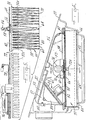
- a mobile surface maintenance machine is indicated generally at 10 and includes a body 12 which will typically be mounted on a plurality of wheels. Conventionally, there may be two rear wheels and a front wheel or there may be a reverse of this wheel arrangement. The driver or operator will be located on a seat 14 and will have a steering wheel 16 and suitable controls for operating the machine.
- the brush 18 will direct dust and debris into a hopper 22. It is important in a sweeping machine of this type to minimize what is characterized as "dusting" and that occurs when the filter which is a part of the dust collection system becomes clogged and no longer will pass air through to the vacuum fan.
- the present invention is directed toward cleaning the filter to prevent dusting.
- the air cleaning system includes a vacuum fan 24 which is connected through a conduit 26 with a filter housing 28 within which is positioned a pleated filter 30. The air flow path created by the fan 24 will begin within the debris hopper 22, as indicated by arrow 32. The dust laden air will pass through a baffle plate 34 and then through the filter 30.
- the dust-free air After passing through the filter 30, as indicated by the arrows 36, the dust-free air will flow into the housing 28, then through the conduit 26 to the vacuum fan, after which it is exhausted to atmosphere.
- the vacuum fan is driven by a hydraulic motor controlled by an electro-hydraulic valve.
- Figs. 2 through 6 illustrate the details of the filter housing, the filter, and the shaker system for the filter.
- the filter 30, Figs. 3, 4 and 5 has a non-woven media formed into a plurality of pleats 38, each of which is connected by lower folds 40 and upper folds 42.
- the filter is positioned within filter housing 28 and the filter will rest upon a shoulder 44 which is a part of the housing.
- the housing 28 has an air inlet 48 through which the air is drawn by the vacuum fan 24.
- On top of the filter there is a cover 50, which is a part of the filter housing.
- the space above the filter, or at its downstream side, is divided into two chambers 52 and 54.
- a wall 56 provides division between the two chambers.
- the wall 56 may be integrally molded with the cover and there may be a seal element 58 along the lower edge of the wall 56, between it and a screen mesh 60 which forms the top of the filter assembly.
- Each of the chambers 52 and 54 includes an identical electrically-operated valve assembly 62 which controls the passage of air from each of the chambers, after it has been drawn through the filter. After air passes through an open valve assembly, it will flow into a back chamber 51, to the conduit 26 and then to the vacuum fan.
- a differential pressure (Delta P) switch 102 is shown in Fig. 4. It may be located wherever convenient in the filter cover 50, and senses the difference in air pressure between the space above the filter and ambient atmosphere.
- the filter element 38 is a single pleated filter formed of a suitable non-woven media. It is separated into two sections by a divider or separator 64 shown in Fig. 5, which may have a generally T-shaped configuration, with the top of the T being indicated at 66, or may be otherwise configured. Each of the sections of pleats, the left-hand section being indicated at 68 in Fig. 5 and the right-hand section at 70 in Fig. 5, will be cleaned by being vibrated by means of a comb; 72 for the left-hand side and 74 for the right-hand side.
- the combs may be formed of a suitable plastic and each will have downwardly-extending teeth 72a and 74a which extend between adjacent pleats.
- the combs will be moved by solenoids indicated at 76 in Fig. 3 and shown and described in more detail in the copending '372 application.
- Each of the solenoids 76 is mounted on a plate 78, with the plates overlying the screen mesh 60.
- Each bar 82 in turn is attached to a comb.
- the solenoid when the solenoid receives pulsed electrical power it will move the bar 82 and thus one of the combs in a direction toward the solenoid and when power is removed, the return spring 80 will move the bar 82 and an associated comb in the opposite direction, thus providing vibratory motion to the pleats.
- the combs are not in contact with each other and are separated by the divider 64.
- vibratory motion of one set of pleats caused by applying pulsed power to one solenoid will only impart vibratory shaking motion to one pleat section, with the other pleat section remaining isolated and stationary.
- the incoming air flowing in the direction of arrows 36 will pass through the inlet 48, which is common to both pleated filter sections, and then the air will be divided and will pass through the generally equal pleat sections 68 and 70, through the screen mesh 60, and then into the two chambers 52 and 54. Assuming a cleaning action is not taking place, the air will pass through the open valve assemblies 62, into the back chamber 51, to the conduit 26, and then to the vacuum fan 24.
- Each of the valve assemblies 62 includes a valve element 84 shown in Fig. 6 and having a generally conical configuration.
- the element 84 has a peripheral annular flange 86, which in the closed position will be seated against a generally circular annular plate 88, which is attached to cross plate 87 with screws 89.
- a solenoid 90 is attached to a mounting bracket 92, with the solenoid plunger 94 being connected to valve stem 93.
- Valve element 84 is attached to valve stem 93 in conventional manner with two flat washers 103 and nut 105.
- the valve stem 93 carries a cross pin 96 which may contact a portion 95 of bracket 92 to limit upward movement of the valve stem 93 and the valve element 84 to the position shown in Fig. 6.
- the cross pin limits the extent of the air opening or the size of the air flow passage through the valve assembly 62.
- No return spring is required, as the valve is opened by air flow and closed by activation of the solenoid 90.
- An offset strap 97 connects bracket 92 to annular plate 88.
- a tubular member 99 is attached to strap 97, and a bushing 101 within tubular member 99 serves as a guide for valve stem 93 to slide in freely.
- Tubular member 99, strap 97, bracket 92 and annular plate 88 together comprise one welded assembly.
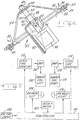
- the control circuit for operation of the shakers and the valve assemblies is indicated in Fig. 7.
- the controller 98 will receive an input signal 100 from the vacuum fan control valve and will place and maintain the filter cleaning system in a ready state.
- a further input from the differential pressure (Delta P) switch 102 may be used to sense the pressure differential across the filter sections and thereby serve to initiate a cleaning cycle.
- the left air valve is indicated at 104 and the right air valve is indicated at 106, the air valves being the valve assemblies shown generally at 62 and described in connection with the description of Fig. 6.
- the shaker coils indicated at 108 and 110 are the solenoids 76 which move the combs 72 and 74 to vibrate the pleated filter sections.
- the controller 98 may be connected to a clock time duration circuit 112 for the left side shaker coil and air valve and to a clock time duration circuit 114 for the right side shaker coil and air valve.
- the Delta P switch will sense the pressure differential across the filter, which is indicative of the degree to which the filter has become clogged and is limiting the passage of air, and at a predetermined pressure differential will signal the controller to initiate a cleaning cycle.
- the controller will first cause one of the filter sections to be cleaned and then the other. For example, if the left side is to be cleaned first, the left air valve will be closed and the left shaker coil 108 will be operated by the application of a signal from the clock circuit 112 through an amplifier 116 to the shaker coil.
- the clock circuit 112 will determine the period during which the shaker coil is pulsed, and it is the application of pulsed power which is used to vibrate the pleats to clean them.
- the left air valve will open and the right air valve will be closed.
- the right shaker coil 110 will then receive an operating signal from clock circuit 114 through amplifier 118 and it will then operate for a predetermined period of time in order to clean the right side of the single filter element.
- the invention should not be limited to an operating system in which the pressure drop across the filter triggers operation of the cleaning cycle. Cleaning may be done on a timed basis or manually, when required by the operator, once the operator has noticed that the machine is dusting.
- Filters must be stationary when they are performing their filter function. It is for this reason that the two sections of the single filter element are isolated and the vibratory motion applied to one side is kept from effecting or imparting movement to the other side.
- an air filter can only remove dust from a certain amount of air, and more specifically, the volume of air passing through a filter must not exceed what is called the "critical air velocity.” If this air velocity is exceeded, some of the airborne dust particles will be driven into the interior of the filter medium rather than lodging on its surface and even a vigorous shaking will not dislodge them. The filter becomes progressively more plugged until it is useless and must be discarded. It is for this reason that the cross pin 96 limits the air flow passage through either valve assembly 62 to a valve below the critical air velocity.
- the vacuum fan develops enough suction to pull 450 cubic ft. per minute (cfm) of air through the system when both valve assemblies are open and that the filter has 78.78 sq. ft. of area in its pleats, so the air velocity is 5.7 ft./min. This is below the critical velocity which is about 7.5 ft./min. for the type of filter and shaker system being used in this example.
- the critical velocity which is about 7.5 ft./min. for the type of filter and shaker system being used in this example.
- the air passage is restricted during the cleaning cycle so that only 280 cfm passes through the open half of the filter.
- This restricted air flow is more than 50 percent of the total 450 cfm because the fan characteristic is such that it develops more vacuum if its intake is restricted.
- the effect is to have 7.11 ft./min. of air flow through the open side, which is below the critical velocity but enough to maintain the dust collection system working adequately during the period of filter cleaning.
Landscapes
- Chemical & Material Sciences (AREA)
- Chemical Kinetics & Catalysis (AREA)
- Engineering & Computer Science (AREA)
- Architecture (AREA)
- Civil Engineering (AREA)
- Structural Engineering (AREA)
- Mechanical Engineering (AREA)
- Filtering Of Dispersed Particles In Gases (AREA)
- Cleaning In General (AREA)
Applications Claiming Priority (2)
| Application Number | Priority Date | Filing Date | Title |
|---|---|---|---|
| US09/112,393 US6117200A (en) | 1996-04-15 | 1998-07-09 | Electromagnetic filter cleaning system |
| US112393 | 1998-07-09 |
Publications (2)
| Publication Number | Publication Date |
|---|---|
| EP0970652A2 true EP0970652A2 (de) | 2000-01-12 |
| EP0970652A3 EP0970652A3 (de) | 2000-12-13 |
Family
ID=22343654
Family Applications (1)
| Application Number | Title | Priority Date | Filing Date |
|---|---|---|---|
| EP99305233A Withdrawn EP0970652A3 (de) | 1998-07-09 | 1999-07-01 | Elektromagnetisches Filterreinigungssystem |
Country Status (2)
| Country | Link |
|---|---|
| US (1) | US6117200A (de) |
| EP (1) | EP0970652A3 (de) |
Cited By (8)
| Publication number | Priority date | Publication date | Assignee | Title |
|---|---|---|---|---|
| US6854157B2 (en) | 2002-02-13 | 2005-02-15 | Federal Signal Corporation | Debris collection systems and vehicles |
| EP1535564A2 (de) | 2003-11-28 | 2005-06-01 | Alfred Kärcher GmbH & Co. KG | Bodenreinigungsmaschine |
| EP1716801A3 (de) * | 2005-04-25 | 2009-04-29 | LG Electronics Inc. | Automatische Reinigungsvorrichtung |
| USD626708S1 (en) | 2008-03-11 | 2010-11-02 | Royal Appliance Mfg. Co. | Hand vacuum |
| US8069529B2 (en) | 2008-10-22 | 2011-12-06 | Techtronic Floor Care Technology Limited | Handheld vacuum cleaner |
| CN108185920A (zh) * | 2017-12-29 | 2018-06-22 | 宁波梦居智能科技有限公司 | 一种扫地机的智能控制系统 |
| CN110804980A (zh) * | 2019-11-01 | 2020-02-18 | 青岛港国际股份有限公司 | 一种路面无尘清扫机及其清扫方法 |
| US12044197B2 (en) | 2018-06-07 | 2024-07-23 | Propulsa Innovations Inc. | Air filtration system for combustion engine and combustion engine including same |
Families Citing this family (37)
| Publication number | Priority date | Publication date | Assignee | Title |
|---|---|---|---|---|
| US6924040B2 (en) | 1996-12-12 | 2005-08-02 | United Technologies Corporation | Thermal barrier coating systems and materials |
| DE10033102B4 (de) * | 2000-07-07 | 2008-09-25 | Hilti Aktiengesellschaft | Filter mit Reinigungsvorrichtung für gefaltete Staubfilterorgane |
| US7051399B2 (en) | 2001-07-30 | 2006-05-30 | Tennant Company | Cleaner cartridge |
| US8051861B2 (en) | 2001-07-30 | 2011-11-08 | Tennant Company | Cleaning system utilizing purified water |
| US6959466B2 (en) * | 2002-09-06 | 2005-11-01 | Tennant Company | Power management system for street sweeper |
| CN2693166Y (zh) * | 2002-10-15 | 2005-04-20 | 松下电器产业株式会社 | 电动吸尘器 |
| WO2005011755A2 (en) | 2003-07-30 | 2005-02-10 | Tennant Company | Ultraviolet sanitation device |
| US8028365B2 (en) | 2003-09-02 | 2011-10-04 | Tennant Company | Hard and soft floor cleaning tool and machine |
| US7199711B2 (en) | 2004-11-12 | 2007-04-03 | Tennant Company | Mobile floor cleaner data communication |
| KR101139115B1 (ko) | 2005-05-05 | 2012-04-30 | 텐난트 컴파니 | 바닥 쓸기 및 세척장치 |
| KR20070002513A (ko) * | 2005-06-30 | 2007-01-05 | 삼성전자주식회사 | 공기청정기 |
| US8584294B2 (en) | 2005-10-21 | 2013-11-19 | Tennant Company | Floor cleaner scrub head having a movable disc scrub member |
| DE102006007442A1 (de) * | 2006-02-17 | 2007-08-23 | BSH Bosch und Siemens Hausgeräte GmbH | Reinigungsvorrichtung für ein Bauteil eines Haushaltswäschetrockners |
| JP5185551B2 (ja) * | 2007-03-19 | 2013-04-17 | 日立工機株式会社 | 集塵機 |
| CN101290151B (zh) * | 2007-04-18 | 2010-05-26 | 海尔集团公司 | 空调过滤网自清洁装置 |
| US7981175B2 (en) * | 2007-04-18 | 2011-07-19 | Cnh America Llc | Self-cleaning blow-off |
| EP1985220B1 (de) | 2007-04-24 | 2016-05-25 | Hako GmbH | Kehrsaugmaschine |
| GB2450717A (en) * | 2007-07-04 | 2009-01-07 | Black & Decker Inc | Power cutter including air filter cleaning mechanism |
| GB2450720A (en) * | 2007-07-04 | 2009-01-07 | Black & Decker Inc | Power cutter with pleated filter |
| US8272134B2 (en) * | 2007-07-04 | 2012-09-25 | Black & Decker Inc. | Power cutter |
| US8117711B2 (en) * | 2007-11-05 | 2012-02-21 | Schwarze Industries, Inc. | High efficiency intake hood system for mobile sweeper vehicles |
| US20090183633A1 (en) * | 2007-12-24 | 2009-07-23 | Schiller Marc I | Filter comb apparatus and method |
| US8327487B2 (en) | 2008-01-31 | 2012-12-11 | Black & Decker Inc. | Vacuum filter cleaning device |
| EP2734098B1 (de) * | 2011-07-22 | 2016-09-07 | Alfred Kärcher GmbH & Co. KG | Kehrmaschine mit druckbehälter zur abreinigung des filters |
| CN103197495B (zh) * | 2012-01-04 | 2015-06-10 | 中强光电股份有限公司 | 气体过滤模块及投影装置 |
| US9038236B2 (en) | 2012-04-25 | 2015-05-26 | Shop Vac Corporation | Filter shaker |
| US10948810B2 (en) * | 2016-09-15 | 2021-03-16 | Sony Corporation | Projection-type image display apparatus, filter apparatus, control apparatus, and control method |
| EP3666148B1 (de) | 2017-09-11 | 2021-12-08 | SharkNinja Operating LLC | Reinigungsvorrichtung |
| US11426038B2 (en) | 2017-09-11 | 2022-08-30 | Sharkninja Operating Llc | Cleaning device |
| EP3873314B1 (de) | 2018-11-01 | 2023-08-30 | SharkNinja Operating LLC | Reinigungsvorrichtung |
| WO2020132032A1 (en) | 2018-12-18 | 2020-06-25 | Sharkninja Operating Llc | Cleaning device |
| US11426044B1 (en) | 2018-12-18 | 2022-08-30 | Sharkninja Operating Llc | Cleaning device |
| US11219345B2 (en) | 2019-10-31 | 2022-01-11 | Sharkninja Operating Llc | Replacement head for a vacuum |
| US11452414B2 (en) | 2019-10-31 | 2022-09-27 | Sharkninja Operating Llc | Replacement head for a vacuum |
| US11266283B2 (en) | 2019-10-31 | 2022-03-08 | Sharkninja Operating Llc | Replacement head for a vacuum |
| US11179014B2 (en) | 2020-02-19 | 2021-11-23 | Sharkninja Operating Llc | Cleaning device system and method for use |
| US12209771B1 (en) * | 2021-11-29 | 2025-01-28 | Amazon Technologies, Inc. | Air filtration system for datacenter or other building |
Family Cites Families (12)
| Publication number | Priority date | Publication date | Assignee | Title |
|---|---|---|---|---|
| US3545178A (en) * | 1967-07-06 | 1970-12-08 | Buell Eng Co | Bag type separator apparatus having cleaning means therefor |
| US3543483A (en) * | 1967-07-06 | 1970-12-01 | Buell Eng Co | Separator apparatus |
| US3938971A (en) * | 1974-10-07 | 1976-02-17 | The Air Preheater Company, Inc. | Bag filter cleaning device |
| US4099940A (en) * | 1977-03-17 | 1978-07-11 | Fmc Corporation | Impulse filter cleaner |
| US4345353A (en) * | 1979-07-23 | 1982-08-24 | Tennant Company | Filtering device |
| US4258451A (en) * | 1979-07-23 | 1981-03-31 | Tennant Company | Surface sweeping machine |
| US4787923A (en) * | 1986-08-27 | 1988-11-29 | Tennant Company | Apparatus for cleaning an air filter |
| US5194077A (en) * | 1990-03-20 | 1993-03-16 | Clarke Industries, Inc. | Dual chamber filter assembly with shaker |
| US5013333A (en) * | 1990-04-13 | 1991-05-07 | Tennant Company | Unattended air cleaning system for surface maintenance machine |
| DE4138223C1 (en) * | 1991-11-21 | 1993-02-18 | Alfred Kaercher Gmbh & Co, 7057 Winnenden, De | Vacuum cleaner with cleaning unit for filter - has separate filters closing through holes in parallel between dust collector and suction unit |
| US5829094A (en) * | 1997-02-19 | 1998-11-03 | Tennant Company | Sweeper with electromagnetic filter cleaning |
| US5711775A (en) * | 1996-04-15 | 1998-01-27 | Tennant Company | Sweeper with electromagnetic filter cleaning |
-
1998
- 1998-07-09 US US09/112,393 patent/US6117200A/en not_active Expired - Fee Related
-
1999
- 1999-07-01 EP EP99305233A patent/EP0970652A3/de not_active Withdrawn
Cited By (10)
| Publication number | Priority date | Publication date | Assignee | Title |
|---|---|---|---|---|
| US6854157B2 (en) | 2002-02-13 | 2005-02-15 | Federal Signal Corporation | Debris collection systems and vehicles |
| US7281296B2 (en) | 2002-02-13 | 2007-10-16 | Federal Signal Corporation | Debris collection systems, vehicles, and methods |
| EP1535564A2 (de) | 2003-11-28 | 2005-06-01 | Alfred Kärcher GmbH & Co. KG | Bodenreinigungsmaschine |
| EP1535564A3 (de) * | 2003-11-28 | 2008-04-09 | Alfred Kärcher GmbH & Co. KG | Bodenreinigungsmaschine |
| EP1716801A3 (de) * | 2005-04-25 | 2009-04-29 | LG Electronics Inc. | Automatische Reinigungsvorrichtung |
| USD626708S1 (en) | 2008-03-11 | 2010-11-02 | Royal Appliance Mfg. Co. | Hand vacuum |
| US8069529B2 (en) | 2008-10-22 | 2011-12-06 | Techtronic Floor Care Technology Limited | Handheld vacuum cleaner |
| CN108185920A (zh) * | 2017-12-29 | 2018-06-22 | 宁波梦居智能科技有限公司 | 一种扫地机的智能控制系统 |
| US12044197B2 (en) | 2018-06-07 | 2024-07-23 | Propulsa Innovations Inc. | Air filtration system for combustion engine and combustion engine including same |
| CN110804980A (zh) * | 2019-11-01 | 2020-02-18 | 青岛港国际股份有限公司 | 一种路面无尘清扫机及其清扫方法 |
Also Published As
| Publication number | Publication date |
|---|---|
| US6117200A (en) | 2000-09-12 |
| EP0970652A3 (de) | 2000-12-13 |
Similar Documents
| Publication | Publication Date | Title |
|---|---|---|
| US6117200A (en) | Electromagnetic filter cleaning system | |
| US4359330A (en) | Self-cleaning pulsed air cleaner with integral precleaner | |
| US4661129A (en) | Filter cleaning device | |
| EP0860554B1 (de) | Kehrmaschine mit elektromagnetischer Filterreinigung | |
| EP0453177B1 (de) | Selbständig arbeitendes Luftreinigungssystem für Oberflächenreinigungsmaschinen | |
| AU613754B2 (en) | Air filtering apparatus | |
| EP0878583B1 (de) | Kehrgerät und Filter mit elektromagnetischer Filterreinigung | |
| CA1040114A (en) | Bag filter cleaning device | |
| US20170188770A1 (en) | Ambient Air Backflushed Filter Vacuum | |
| EP0285247A1 (de) | Kontinuierlich betriebener und gereinigter Filterapparat | |
| CN104918673A (zh) | 可清洗过滤器 | |
| US20230263351A1 (en) | Filter device and method for dedusting same | |
| CN105361815B (zh) | 过滤器振动装置及其自清洁方法及吸尘器 | |
| WO2009041890A2 (en) | Methods, device and valve for cleaning a separator filter | |
| US6280491B1 (en) | Cartridge filter | |
| JP2010011905A (ja) | 電気掃除機 | |
| US4792344A (en) | Air filtering method and apparatus | |
| CN113573793B (zh) | 用于集尘器的清洁装置和清洁方法 | |
| JPH06226169A (ja) | 粉末スプレイコーティング装置 | |
| JPH035844B2 (de) | ||
| KR102208194B1 (ko) | 오일 미스트 집진기 | |
| EP2257674B1 (de) | Filterschüttleranordnung für eine kehrmaschine | |
| KR200362736Y1 (ko) | 자력을 이용한 미세 철분 제거장치 | |
| JPH03224646A (ja) | 集じん装置及びその集じん方法 | |
| RU2063786C1 (ru) | Сопловый фильтр |
Legal Events
| Date | Code | Title | Description |
|---|---|---|---|
| PUAI | Public reference made under article 153(3) epc to a published international application that has entered the european phase |
Free format text: ORIGINAL CODE: 0009012 |
|
| AK | Designated contracting states |
Kind code of ref document: A2 Designated state(s): DE FR GB |
|
| AX | Request for extension of the european patent |
Free format text: AL;LT;LV;MK;RO;SI |
|
| PUAL | Search report despatched |
Free format text: ORIGINAL CODE: 0009013 |
|
| RIC1 | Information provided on ipc code assigned before grant |
Free format text: 7A 47L 9/20 A, 7A 47L 11/20 B, 7A 47L 11/24 B, 7B 01D 46/52 B, 7E 01H 1/08 B |
|
| AK | Designated contracting states |
Kind code of ref document: A3 Designated state(s): AT BE CH CY DE DK ES FI FR GB GR IE IT LI LU MC NL PT SE |
|
| AX | Request for extension of the european patent |
Free format text: AL;LT;LV;MK;RO;SI |
|
| 17P | Request for examination filed |
Effective date: 20010126 |
|
| AKX | Designation fees paid |
Free format text: DE FR GB |
|
| STAA | Information on the status of an ep patent application or granted ep patent |
Free format text: STATUS: THE APPLICATION IS DEEMED TO BE WITHDRAWN |
|
| 18D | Application deemed to be withdrawn |
Effective date: 20040203 |