EP0969695B1 - System consisting of a microphone and a preamplifier - Google Patents
System consisting of a microphone and a preamplifier Download PDFInfo
- Publication number
- EP0969695B1 EP0969695B1 EP99202157A EP99202157A EP0969695B1 EP 0969695 B1 EP0969695 B1 EP 0969695B1 EP 99202157 A EP99202157 A EP 99202157A EP 99202157 A EP99202157 A EP 99202157A EP 0969695 B1 EP0969695 B1 EP 0969695B1
- Authority
- EP
- European Patent Office
- Prior art keywords
- microphone
- diaphragm
- frequency
- amplifier
- pressure equalization
- Prior art date
- Legal status (The legal status is an assumption and is not a legal conclusion. Google has not performed a legal analysis and makes no representation as to the accuracy of the status listed.)
- Expired - Lifetime
Links
Images


Classifications
-
- H—ELECTRICITY
- H04—ELECTRIC COMMUNICATION TECHNIQUE
- H04R—LOUDSPEAKERS, MICROPHONES, GRAMOPHONE PICK-UPS OR LIKE ACOUSTIC ELECTROMECHANICAL TRANSDUCERS; ELECTRIC HEARING AIDS; PUBLIC ADDRESS SYSTEMS
- H04R19/00—Electrostatic transducers
- H04R19/01—Electrostatic transducers characterised by the use of electrets
- H04R19/016—Electrostatic transducers characterised by the use of electrets for microphones
-
- H—ELECTRICITY
- H04—ELECTRIC COMMUNICATION TECHNIQUE
- H04R—LOUDSPEAKERS, MICROPHONES, GRAMOPHONE PICK-UPS OR LIKE ACOUSTIC ELECTROMECHANICAL TRANSDUCERS; ELECTRIC HEARING AIDS; PUBLIC ADDRESS SYSTEMS
- H04R1/00—Details of transducers, loudspeakers or microphones
- H04R1/20—Arrangements for obtaining desired frequency or directional characteristics
- H04R1/22—Arrangements for obtaining desired frequency or directional characteristics for obtaining desired frequency characteristic only
- H04R1/222—Arrangements for obtaining desired frequency or directional characteristics for obtaining desired frequency characteristic only for microphones
-
- H—ELECTRICITY
- H04—ELECTRIC COMMUNICATION TECHNIQUE
- H04R—LOUDSPEAKERS, MICROPHONES, GRAMOPHONE PICK-UPS OR LIKE ACOUSTIC ELECTROMECHANICAL TRANSDUCERS; ELECTRIC HEARING AIDS; PUBLIC ADDRESS SYSTEMS
- H04R25/00—Electric hearing aids
- H04R25/60—Mounting or interconnection of hearing aid parts, e.g. inside tips, housings or to ossicles
- H04R25/604—Mounting or interconnection of hearing aid parts, e.g. inside tips, housings or to ossicles of acoustic or vibrational transducers
Definitions
- This invention relates to a system consisting of a microphone and a preamplifier, wherein the microphone comprises a housing having therein an opening to the surroundings, a diaphragm and a backplate, while the amplifier is coupled to the system consisting of the diaphragm and the backplate and has a field effect transistor as input element.
- the microphone comprises a housing having therein an opening to the surroundings, a diaphragm and a backplate
- the amplifier is coupled to the system consisting of the diaphragm and the backplate and has a field effect transistor as input element.
- the microphone is more particularly the microphone of a hearing aid.
- Such microphones and the associated amplifiers have been miniaturized further and further over the last years, so that, for instance, they can be accommodated inside, instead of outside, the ear, or even in the auditory duct. According as a microphone is smaller, its capacitance is generally lower. Since the noise produced by an amplifier is inversely proportional to the capacitance at the input thereof, such miniaturization of the microphone has as a drawback that the noise thereof increases more and more and has actually become dominant with respect to the noise of the amplifier, which used to be determinative.
- a pressure equalization opening is present, which ensures that the back volume is not going to function as a barometer, thereby adversely affecting the operation of the microphone.
- the size of this pressure equalization opening also influences the noise behavior, because, in acoustic terms, it constitutes a resistance, and must therefore be dimensioned very accurately, with tolerances in the order of micrometers, which is a great technical problem.
- an element such as a gauze or a drop of glue, is provided to attenuate high frequencies.
- Such elements can become soiled, for instance by earwax, so that not only the snout may become clogged, but also the frequency behavior is uncontrollably influenced.
- a miniature microphone has a frequency response with a resonance peak in the audible high-frequency range, which also affects the noise behavior adversely. If the resonance peak is placed outside the audible frequency range, this, in turn, has yet other adverse consequences for the noise behavior.
- the object of the invention is to provide a solution to the above-outlined problems with noise in the low-frequency range, and to that end the invention provides, in a first embodiment, a system of the above-mentioned kind, wherein in the housing, in a space which is bounded by, on the one hand, the diaphragm and, on the other, the housing wall and which does not comprise the opening to the surroundings, a pressure equalization opening is present, which has a diameter such that in the audible audiospectrum it does not make an essential contribution to the suppression of low frequencies, and wherein, in the input stage of the amplifier, at the output of a MOS field effect transistor forming the input element, a high-pass filter is arranged.
- either a pressure equalization hole is made in a housing wall instead of in the diaphragm, or the pressure equalization hole in the diaphragm is made so small, for instance about 20 ⁇ m, that it does not make any appreciable contribution to the noise.
- the low-frequency filtering which is usually obtained with the pressure equalization hole, is also lost. Low frequencies are not of importance for the audibility of speech and can, if they are not suppressed, lead to overloading of the hearing aid. Therefore, according to the invention, this low-frequency filtering has been moved to the preamplifier coupled to the transducer.
- the noise of an amplifier is also inversely proportional to the root of the real part of the impedance at the input thereof, so that a high input impedance, as with a MOS-FET, is favorable to the noise behavior.
- a further object of the invention is to provide a solution to the above-outlined problems with noise in the high-frequency range, and to that effect, according to a second embodiment in the system of the first embodiment in the amplifier, a low-pass filter coupled to the output of a MOS field effect transistor forming the input element is arranged.
- the filter is a second-order active filter.
- the filter has an externally settable filter curve, that is, a settable cut-off frequency and/or quality factor.
- the components determining the filter curve can be arranged both in the microphone housing and outside thereof.
- an important advantage of the use of an electronic filter for cutting off high frequencies is that it affords greater freedom in positioning the resonance peak in the response characteristic of the microphone and also that this position does not need to be as accurate.
- This resonance peak can be influenced by varying the stiffness of the diaphragm and/or varying the distance between the backplate and the diaphragm.
- the resonance peak is placed in the audible frequency range to enable attenuating noise of frequencies above that of the resonance peak.
- the resonance peak can be placed outside the audible range and with the aid of the electronic filter a virtually flat frequency response in the desired audible frequency range can be realized. Further, it is no longer necessary to provide elements in the snout to influence the frequency behavior. Through all these measures, the microphone capsule can be fabricated more cheaply, because fewer parts and/or manufacturing steps are needed, and the tolerances for the positions or dimensioning of a number of parts of the microphone do not need to be as accurate.
- telecommunication equipment In addition to hearing aids, telecommunication equipment also forms a field of application of the microphone according to the invention.
- Fig. 1 shows an exploded view of a microphone of the electret type, in which the invention can be applied. It is noted with emphasis, however, that the invention is applicable with any microphone in which the noise of the pressure equalization hole has a great influence on the overall noise of the microphone.
- the microphone comprises a first, box-shaped member 1, to which is connected a sound inlet opening, the so-called snout 2.
- a backplate 3, known per se is mounted, and above the backplate, spaced therefrom, the diaphragm 4 is mounted in or on the circumferential edge of the box 1.
- a mounting plate 5 is arranged above the diaphragm 4 arranged above the diaphragm 4 .
- a hole is provided to enable connecting the circuit 6 electrically with the diaphragm.
- the housing is closed with the aid of a cover 7.
- a pressure equalization opening of a diameter of a few tens to hundreds of ⁇ m.
- the above-described microphone is of a conventional type and is sold by applicant in the so-called "90-series". It is known that the diameter of the pressure equalization hole has an influence on the low-frequency behavior of the microphone.
- Fig. 2 shows this influence of the diameter of the pressure equalization opening on the frequency characteristic.
- curve I shows the transmission at a hole diameter of 49 ⁇ m
- curve II at a hole diameter of 93 ⁇ m
- curve III at a diameter of 150 ⁇ m.
- the diameter of the hole in the diaphragm 4 is, for instance, 30 ⁇ m or less, so that the crossover point below which frequency loss occurs comes to lie outside the audible audiospectrum, for instance at 20 Hz.
- Another possibility is not to provide a pressure equalization hole in the diaphragm but to provide an acoustic filter in the wall portion 7 of the housing which, together with the diaphragm, forms the back volume, so that the hole does not have any influence on the frequency characteristic.
- This acoustic filter can have the form of a tube or a small aperture. Measurement has shown that when the pressure equalization hole is reduced in this way or moved to the housing wall, the microphone's inherent noise decreases by about 6 dB.
- An additional advantage of the invention is that by the choice of either a very small diameter of the pressure equalization hole, or the provision thereof in a housing wall, the tolerance of the diameter of this hole no longer plays a role.
- the increasing quality requirements imposed on microphones in respect of low-frequency behavior require a hole diameter of, for instance, 50 ⁇ m with a tolerance of, for instance, 1 ⁇ m, which is very difficult to realize.
- this problem no longer plays a role because the equality of the low-frequency filters, as they can now be accommodated in an IC for the preamplifier, is by definition large.
- paired microphones which at present is conventional in hearing aids to improve the directional response pattern, it is an advantage that the low-frequency behavior is no longer determined by the microphone itself, but by an external filter, because in such paired microphones very stringent requirements are imposed on the equality of the phase and frequency characteristic.
- Fig. 3 schematically shows a first embodiment of a preamplifier which can be used in the system according to the invention.
- the amplifier is built up around two MOS-FETs 31 and 32, which are fabricated in CMOS technique, which makes it possible to give the MOS-FET 31 an input resistance of a few TeraOhms and an input capacitance of only 1.6 pF.
- Other input elements having a high input impedance are also applicable, of course, and it is also possible to include the two stages of the amplifier in different techniques and even in different integrated circuits.
- the high-pass filter is realized by the capacitor 33 and the resistor 34 at the input of MOS-FET 32.
- the desired low-frequency crossover point can be fixed very easily, because they can be manufactured accurately in IC technique.
- the value of the capacitor 33 in practice amounts to a few hundreds of pF and the value of the resistor 34 a few M ⁇ .
- the amplified microphone signal is available for further processing.
- the assembly of microphone and amplifier functions optimally from a noise suppression point of view, because the signal is attenuated for low frequencies only at a late stage.
- the filter consisting of the capacitor 33 and the resistor 34, also low-frequency noise of the input section of the amplifier is attenuated.
- an improvement of the noise behavior of about 6 dB has been found to be possible, which, in terms of hearing, corresponds to a halving of the observed noise.
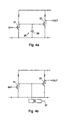
- Fig. 4a shows the circuit according to Fig. 3, in which now, according to the second embodiment, a simple variant of a low-pass filter 35 in the form of a capacitor 36 is arranged.
- Fig. 4b shows more schematically that the low-pass filter 35 can be integrated into the amplifier proper or outside thereof, accommodated in the microphone housing or not. Further, the filter can be externally settable via 37, both as regards cut-off frequency and quality factor. Setting can be done manually, or the filter, if it is suited therefor, can be programmed by means of a serial or parallel interface. Various solutions to that end are well known to those skilled in the art of electronics.
- the variants of the first and second embodiment of the invention can be very well combined with each other to realize a microphone with a fully electronically settable frequency characteristic.
Landscapes
- Physics & Mathematics (AREA)
- Engineering & Computer Science (AREA)
- Acoustics & Sound (AREA)
- Signal Processing (AREA)
- Electrostatic, Electromagnetic, Magneto- Strictive, And Variable-Resistance Transducers (AREA)
- Circuit For Audible Band Transducer (AREA)
Description
Claims (7)
- A system consisting of a microphone and a preamplifier, wherein the microphone comprises a housing (1,7) having therein an opening (2) to the surroundings, a diaphragm (4) and a backplate (3), while the amplifier is coupled to the system consisting of the diaphragm and the backplate and has a field effect transistor (31) as input element, characterized in that in the housing, in a space which is bounded by, on the one hand, the diaphragm (4) and, on the other, the housing wall (1,7), and which does not comprise the opening (2) to the surroundings, a pressure equalization opening is present, which has a diameter such that in the audible audiospectrum it does not make an essential contribution to the suppression of low frequencies, and wherein, in the input stage of the amplifier, at the output of a field effect transistor (31) forming the input element, a high-pass filter (31,33,34) is arranged.
- A system according to claim 1, characterized in that the pressure equalization hole is provided in the diaphragm (4) and has a diameter that is less than 30 µm.
- A system according to claim 1, characterized in that the pressure equalization hole is provided in said housing wall.
- A system according to any of the claims 1-3, characterized in that in the amplifier a low-pass filter (35) coupled to the output of a field effect transistor (31) forming the input element is arranged.
- A system according to claim 4, characterized in that the low-pass filter is a second-order filter.
- A system according to claim 4 or 5, characterized in that the cut-off frequency and/or the quality factor of the filter is externally settable (37).
- A system according to claim 4, wherein the microphone has a frequency response with a resonance peak, characterized in that the resonance peak lies outside the audible frequency range.
Priority Applications (1)
| Application Number | Priority Date | Filing Date | Title |
|---|---|---|---|
| DK99202157T DK0969695T3 (en) | 1998-07-02 | 1999-07-02 | System consisting of a microphone and a preamplifier |
Applications Claiming Priority (2)
| Application Number | Priority Date | Filing Date | Title |
|---|---|---|---|
| NL1009544 | 1998-07-02 | ||
| NL1009544A NL1009544C2 (en) | 1998-07-02 | 1998-07-02 | System consisting of a microphone and a preamp. |
Publications (2)
| Publication Number | Publication Date |
|---|---|
| EP0969695A1 EP0969695A1 (en) | 2000-01-05 |
| EP0969695B1 true EP0969695B1 (en) | 2004-06-23 |
Family
ID=19767413
Family Applications (1)
| Application Number | Title | Priority Date | Filing Date |
|---|---|---|---|
| EP99202157A Expired - Lifetime EP0969695B1 (en) | 1998-07-02 | 1999-07-02 | System consisting of a microphone and a preamplifier |
Country Status (5)
| Country | Link |
|---|---|
| US (1) | US6914992B1 (en) |
| EP (1) | EP0969695B1 (en) |
| DE (1) | DE69918224T2 (en) |
| DK (1) | DK0969695T3 (en) |
| NL (1) | NL1009544C2 (en) |
Cited By (1)
| Publication number | Priority date | Publication date | Assignee | Title |
|---|---|---|---|---|
| US7065224B2 (en) | 2001-09-28 | 2006-06-20 | Sonionmicrotronic Nederland B.V. | Microphone for a hearing aid or listening device with improved internal damping and foreign material protection |
Families Citing this family (96)
| Publication number | Priority date | Publication date | Assignee | Title |
|---|---|---|---|---|
| WO2001082649A1 (en) * | 2000-04-26 | 2001-11-01 | Mitsubishi Denki Kabushiki Kaisha | Semiconductor electret capacitor microphone |
| WO2003024149A1 (en) * | 2001-09-10 | 2003-03-20 | Sonion A/S | Miniature speaker with integrated signal processing electronics |
| JP2003230195A (en) * | 2002-02-06 | 2003-08-15 | Hosiden Corp | Electret capacitor microphone |
| US7092538B2 (en) | 2002-04-15 | 2006-08-15 | Knowles Electronics, Llc | Switched microphone buffer |
| US7221766B2 (en) | 2002-04-15 | 2007-05-22 | Knowles Electronics, Llc | Microphone input buffer biasing circuit |
| US7688987B2 (en) | 2002-04-24 | 2010-03-30 | Knowles Electronics, Llc | Electret microphone buffer circuit with significantly enhanced power supply rejection |
| US6888408B2 (en) | 2002-08-27 | 2005-05-03 | Sonion Tech A/S | Preamplifier for two terminal electret condenser microphones |
| US7072482B2 (en) | 2002-09-06 | 2006-07-04 | Sonion Nederland B.V. | Microphone with improved sound inlet port |
| US7415121B2 (en) * | 2004-10-29 | 2008-08-19 | Sonion Nederland B.V. | Microphone with internal damping |
| US7795695B2 (en) | 2005-01-27 | 2010-09-14 | Analog Devices, Inc. | Integrated microphone |
| US7449356B2 (en) * | 2005-04-25 | 2008-11-11 | Analog Devices, Inc. | Process of forming a microphone using support member |
| US7825484B2 (en) * | 2005-04-25 | 2010-11-02 | Analog Devices, Inc. | Micromachined microphone and multisensor and method for producing same |
| US20070071268A1 (en) * | 2005-08-16 | 2007-03-29 | Analog Devices, Inc. | Packaged microphone with electrically coupled lid |
| US7885423B2 (en) | 2005-04-25 | 2011-02-08 | Analog Devices, Inc. | Support apparatus for microphone diaphragm |
| EP1742506B1 (en) | 2005-07-06 | 2013-05-22 | Epcos Pte Ltd | Microphone assembly with P-type preamplifier input stage |
| US20070040231A1 (en) * | 2005-08-16 | 2007-02-22 | Harney Kieran P | Partially etched leadframe packages having different top and bottom topologies |
| US8477983B2 (en) * | 2005-08-23 | 2013-07-02 | Analog Devices, Inc. | Multi-microphone system |
| US8130979B2 (en) * | 2005-08-23 | 2012-03-06 | Analog Devices, Inc. | Noise mitigating microphone system and method |
| US7961897B2 (en) * | 2005-08-23 | 2011-06-14 | Analog Devices, Inc. | Microphone with irregular diaphragm |
| US8351632B2 (en) * | 2005-08-23 | 2013-01-08 | Analog Devices, Inc. | Noise mitigating microphone system and method |
| US8344487B2 (en) * | 2006-06-29 | 2013-01-01 | Analog Devices, Inc. | Stress mitigation in packaged microchips |
| JP4951067B2 (en) * | 2006-07-25 | 2012-06-13 | アナログ デバイシス, インコーポレイテッド | Multiple microphone systems |
| TW200847827A (en) * | 2006-11-30 | 2008-12-01 | Analog Devices Inc | Microphone system with silicon microphone secured to package lid |
| US7694610B2 (en) * | 2007-06-27 | 2010-04-13 | Siemens Medical Solutions Usa, Inc. | Photo-multiplier tube removal tool |
| US8135163B2 (en) * | 2007-08-30 | 2012-03-13 | Klipsch Group, Inc. | Balanced armature with acoustic low pass filter |
| US9357287B2 (en) | 2011-07-07 | 2016-05-31 | Sonion Nederland B.V. | Multiple receiver assembly and a method for assembly thereof |
| EP2590434B1 (en) * | 2011-11-04 | 2016-01-27 | AKG Acoustics GmbH | Filter circuit |
| DK2723102T3 (en) | 2012-10-18 | 2019-01-02 | Sonion Nederland Bv | Transducer, transducer hearing aid and a method of operating the transducer |
| DK2723098T3 (en) | 2012-10-18 | 2017-03-13 | Sonion Nederland Bv | Double transducer with common membrane |
| US9807525B2 (en) | 2012-12-21 | 2017-10-31 | Sonion Nederland B.V. | RIC assembly with thuras tube |
| EP2750413B1 (en) | 2012-12-28 | 2017-02-22 | Sonion Nederland B.V. | Hearing aid device |
| US9676614B2 (en) | 2013-02-01 | 2017-06-13 | Analog Devices, Inc. | MEMS device with stress relief structures |
| US9401575B2 (en) | 2013-05-29 | 2016-07-26 | Sonion Nederland Bv | Method of assembling a transducer assembly |
| EP2849463B1 (en) | 2013-09-16 | 2018-04-04 | Sonion Nederland B.V. | A transducer comprising moisture transporting element |
| DK3550852T3 (en) | 2014-02-14 | 2021-02-01 | Sonion Nederland Bv | A joiner for a receiver assembly |
| EP2908559B1 (en) | 2014-02-18 | 2016-10-05 | Sonion A/S | A method of manufacturing assemblies for hearing aids |
| DK2914018T3 (en) | 2014-02-26 | 2017-01-30 | Sonion Nederland Bv | Speaker, luminaire and method |
| US9432774B2 (en) | 2014-04-02 | 2016-08-30 | Sonion Nederland B.V. | Transducer with a bent armature |
| EP2953380A1 (en) | 2014-06-04 | 2015-12-09 | Sonion Nederland B.V. | Acoustical crosstalk compensation |
| US10167189B2 (en) | 2014-09-30 | 2019-01-01 | Analog Devices, Inc. | Stress isolation platform for MEMS devices |
| US9729974B2 (en) | 2014-12-30 | 2017-08-08 | Sonion Nederland B.V. | Hybrid receiver module |
| EP3051841B1 (en) | 2015-01-30 | 2020-10-07 | Sonion Nederland B.V. | A receiver having a suspended motor assembly |
| EP3057339B1 (en) | 2015-02-10 | 2020-09-23 | Sonion Nederland B.V. | Microphone module with shared middle sound inlet arrangement |
| DK3073764T3 (en) | 2015-03-25 | 2021-05-10 | Sonion Nederland Bv | A hearing aid comprising an insert member |
| US9980029B2 (en) | 2015-03-25 | 2018-05-22 | Sonion Nederland B.V. | Receiver-in-canal assembly comprising a diaphragm and a cable connection |
| DK3133829T3 (en) | 2015-08-19 | 2020-06-22 | Sonion Nederland Bv | AUDIO UNIT WITH IMPROVED FREQUENCY RESPONSE |
| US10433077B2 (en) | 2015-09-02 | 2019-10-01 | Sonion Nederland B.V. | Augmented hearing device |
| US10131538B2 (en) | 2015-09-14 | 2018-11-20 | Analog Devices, Inc. | Mechanically isolated MEMS device |
| US9668065B2 (en) | 2015-09-18 | 2017-05-30 | Sonion Nederland B.V. | Acoustical module with acoustical filter |
| US10021494B2 (en) | 2015-10-14 | 2018-07-10 | Sonion Nederland B.V. | Hearing device with vibration sensitive transducer |
| DK3160157T3 (en) | 2015-10-21 | 2018-12-17 | Sonion Nederland Bv | Vibration-compensated vibroacoustic device |
| US10582303B2 (en) | 2015-12-04 | 2020-03-03 | Sonion Nederland B.V. | Balanced armature receiver with bi-stable balanced armature |
| EP3185584B1 (en) | 2015-12-21 | 2020-04-22 | Sonion Nederland B.V. | Receiver assembly having a distinct longitudinal direction |
| US9866959B2 (en) | 2016-01-25 | 2018-01-09 | Sonion Nederland B.V. | Self-biasing output booster amplifier and use thereof |
| EP3200479A3 (en) | 2016-01-28 | 2017-08-30 | Sonion Nederland B.V. | An assembly comprising an electrostatic sound generator and a transformer |
| DK3232685T3 (en) | 2016-04-13 | 2021-04-19 | Sonion Nederland Bv | A dome for a personal audio device |
| US10078097B2 (en) | 2016-06-01 | 2018-09-18 | Sonion Nederland B.V. | Vibration or acceleration sensor applying squeeze film damping |
| US10257616B2 (en) | 2016-07-22 | 2019-04-09 | Knowles Electronics, Llc | Digital microphone assembly with improved frequency response and noise characteristics |
| DK3703389T1 (en) | 2016-08-26 | 2020-11-09 | Sonion Nederland Bv | Vibration sensor with low-frequency roll-off response curve |
| EP3293985B1 (en) | 2016-09-12 | 2021-03-24 | Sonion Nederland B.V. | Receiver with integrated membrane movement detection |
| US10412477B2 (en) | 2016-09-19 | 2019-09-10 | Wade Goeke | High fidelity, professional grade microphone system for direct coupling to recording components |
| EP3313097B1 (en) | 2016-10-19 | 2020-08-26 | Sonion Nederland B.V. | An ear bud or dome |
| EP3324649A1 (en) | 2016-11-18 | 2018-05-23 | Sonion Nederland B.V. | A transducer with a high sensitivity |
| US10327072B2 (en) | 2016-11-18 | 2019-06-18 | Sonion Nederland B.V. | Phase correcting system and a phase correctable transducer system |
| EP3324538A1 (en) | 2016-11-18 | 2018-05-23 | Sonion Nederland B.V. | A sensing circuit comprising an amplifying circuit |
| US20180145643A1 (en) | 2016-11-18 | 2018-05-24 | Sonion Nederland B.V. | Circuit for providing a high and a low impedance and a system comprising the circuit |
| DK3337184T3 (en) | 2016-12-14 | 2020-06-02 | Sonion Nederland Bv | An armature and a transducer comprising the armature |
| EP3337191B1 (en) | 2016-12-16 | 2021-05-19 | Sonion Nederland B.V. | A receiver assembly |
| DK3337192T3 (en) | 2016-12-16 | 2021-05-10 | Sonion Nederland Bv | A receiver assembly |
| EP3343950A1 (en) | 2016-12-28 | 2018-07-04 | Sonion Nederland B.V. | A magnet assembly |
| DK3702322T3 (en) | 2016-12-30 | 2026-03-16 | Sonion Nederland Bv | MICROELECTROMECHANICAL TRANSDUCER |
| DK3343956T3 (en) | 2016-12-30 | 2021-05-03 | Sonion Nederland Bv | A circuit and a receiver comprising the circuit |
| DK3407626T3 (en) | 2017-05-26 | 2020-07-27 | Sonion Nederland Bv | A receiver assembly comprising an armature and a diaphragm |
| DK3407625T3 (en) | 2017-05-26 | 2021-07-12 | Sonion Nederland Bv | Receiver with venting opening |
| DK3429231T3 (en) | 2017-07-13 | 2023-04-11 | Sonion Nederland Bv | Hearing device including vibration prevention device |
| US10820104B2 (en) | 2017-08-31 | 2020-10-27 | Sonion Nederland B.V. | Diaphragm, a sound generator, a hearing device and a method |
| EP3451688B1 (en) | 2017-09-04 | 2021-05-26 | Sonion Nederland B.V. | A sound generator, a shielding and a spout |
| GB201714956D0 (en) | 2017-09-18 | 2017-11-01 | Sonova Ag | Hearing device with adjustable venting |
| EP4203497A3 (en) | 2017-10-16 | 2023-11-15 | Sonion Nederland B.V. | A personal hearing device |
| EP3471432B1 (en) | 2017-10-16 | 2022-09-14 | Sonion Nederland B.V. | A sound channel element with a valve and a transducer with the sound channel element |
| DK3471437T3 (en) | 2017-10-16 | 2021-02-15 | Sonion Nederland Bv | A valve, a transducer comprising a valve, a hearing device and a method |
| EP3567873B1 (en) | 2018-02-06 | 2021-08-18 | Sonion Nederland B.V. | Method for controlling an acoustic valve of a hearing device |
| EP3531720B1 (en) | 2018-02-26 | 2021-09-15 | Sonion Nederland B.V. | An assembly of a receiver and a microphone |
| DK3531713T3 (en) | 2018-02-26 | 2023-02-06 | Sonion Nederland Bv | Miniature Speaker with Acoustical Mass |
| DK3467457T3 (en) | 2018-04-30 | 2022-10-17 | Sonion Nederland Bv | Vibrationssensor |
| EP3579578B1 (en) | 2018-06-07 | 2022-02-23 | Sonion Nederland B.V. | Miniature receiver |
| US10951169B2 (en) | 2018-07-20 | 2021-03-16 | Sonion Nederland B.V. | Amplifier comprising two parallel coupled amplifier units |
| US11564580B2 (en) | 2018-09-19 | 2023-01-31 | Sonion Nederland B.V. | Housing comprising a sensor |
| EP4300995A3 (en) | 2018-12-19 | 2024-04-03 | Sonion Nederland B.V. | Miniature speaker with multiple sound cavities |
| US11190880B2 (en) | 2018-12-28 | 2021-11-30 | Sonion Nederland B.V. | Diaphragm assembly, a transducer, a microphone, and a method of manufacture |
| EP3675522A1 (en) | 2018-12-28 | 2020-07-01 | Sonion Nederland B.V. | Miniature speaker with essentially no acoustical leakage |
| EP3726855B1 (en) | 2019-04-15 | 2021-09-01 | Sonion Nederland B.V. | A personal hearing device with a vent channel and acoustic separation |
| EP3806494B1 (en) | 2019-10-07 | 2023-12-27 | Sonion Nederland B.V. | Hearing device including an optical sensor |
| US11417611B2 (en) | 2020-02-25 | 2022-08-16 | Analog Devices International Unlimited Company | Devices and methods for reducing stress on circuit components |
| US11981560B2 (en) | 2020-06-09 | 2024-05-14 | Analog Devices, Inc. | Stress-isolated MEMS device comprising substrate having cavity and method of manufacture |
| EP4469388A4 (en) | 2022-01-25 | 2026-01-28 | Analog Devices Inc | LOAD INSULATION FOR INTEGRATED CIRCUIT PACKING INTEGRATION |
Family Cites Families (19)
| Publication number | Priority date | Publication date | Assignee | Title |
|---|---|---|---|---|
| US3197048A (en) * | 1962-12-26 | 1965-07-27 | American Zinc | Self loading transport |
| US4056697A (en) * | 1976-09-03 | 1977-11-01 | Oskar Heil | Movable diaphragm connector method flexible hinge diaphragm surround and electro-acoustic transducer with folded diaphragm with intermediate flexible portions |
| US4063050A (en) * | 1976-12-30 | 1977-12-13 | Industrial Research Products, Inc. | Acoustic transducer with improved electret assembly |
| US4331840A (en) * | 1980-02-22 | 1982-05-25 | Lectret S.A. | Electret transducer with tapered acoustic chamber |
| US4450930A (en) * | 1982-09-03 | 1984-05-29 | Industrial Research Products, Inc. | Microphone with stepped response |
| US4701640A (en) * | 1985-03-11 | 1987-10-20 | Telex Communications, Inc. | Electret transducer and method of fabrication |
| US4764690A (en) * | 1986-06-18 | 1988-08-16 | Lectret S.A. | Electret transducing |
| US5083312A (en) * | 1989-08-01 | 1992-01-21 | Argosy Electronics, Inc. | Programmable multichannel hearing aid with adaptive filter |
| NL9101563A (en) * | 1991-09-17 | 1993-04-16 | Microtel Bv | ELECTROACOUSTIC TRANSDUCENT OF THE ELECTRET TYPE. |
| US5452268A (en) * | 1994-08-12 | 1995-09-19 | The Charles Stark Draper Laboratory, Inc. | Acoustic transducer with improved low frequency response |
| US5589799A (en) * | 1994-09-29 | 1996-12-31 | Tibbetts Industries, Inc. | Low noise amplifier for microphone |
| US5812679A (en) * | 1994-11-30 | 1998-09-22 | Killion; Mead | Electronic damper circuit for a hearing aid and a method of using the same |
| US6466678B1 (en) * | 1994-11-30 | 2002-10-15 | Etymotic Research, Inc. | Hearing aid having digital damping |
| US6031922A (en) * | 1995-12-27 | 2000-02-29 | Tibbetts Industries, Inc. | Microphone systems of reduced in situ acceleration sensitivity |
| NL1002783C2 (en) * | 1996-04-03 | 1997-10-06 | Microtronic Nederland Bv | Integrated microphone / amplifier unit, and amplifier module therefor. |
| AU2923397A (en) * | 1996-04-18 | 1997-11-07 | California Institute Of Technology | Thin film electret microphone |
| US5889872A (en) * | 1996-07-02 | 1999-03-30 | Motorola, Inc. | Capacitive microphone and method therefor |
| US6504937B1 (en) * | 1998-01-06 | 2003-01-07 | Vxi Corporation | Amplifier circuit for electret microphone with enhanced performance |
| US6154547A (en) * | 1998-05-07 | 2000-11-28 | Visteon Global Technologies, Inc. | Adaptive noise reduction filter with continuously variable sliding bandwidth |
-
1998
- 1998-07-02 NL NL1009544A patent/NL1009544C2/en not_active IP Right Cessation
-
1999
- 1999-07-01 US US09/346,220 patent/US6914992B1/en not_active Expired - Lifetime
- 1999-07-02 DE DE69918224T patent/DE69918224T2/en not_active Expired - Lifetime
- 1999-07-02 EP EP99202157A patent/EP0969695B1/en not_active Expired - Lifetime
- 1999-07-02 DK DK99202157T patent/DK0969695T3/en active
Cited By (1)
| Publication number | Priority date | Publication date | Assignee | Title |
|---|---|---|---|---|
| US7065224B2 (en) | 2001-09-28 | 2006-06-20 | Sonionmicrotronic Nederland B.V. | Microphone for a hearing aid or listening device with improved internal damping and foreign material protection |
Also Published As
| Publication number | Publication date |
|---|---|
| DE69918224D1 (en) | 2004-07-29 |
| US6914992B1 (en) | 2005-07-05 |
| NL1009544C2 (en) | 2000-01-10 |
| EP0969695A1 (en) | 2000-01-05 |
| DE69918224T2 (en) | 2005-06-30 |
| DK0969695T3 (en) | 2004-11-01 |
Similar Documents
| Publication | Publication Date | Title |
|---|---|---|
| US6914992B1 (en) | System consisting of a microphone and a preamplifier | |
| US7756285B2 (en) | Hearing aid with tuned microphone cavity | |
| US5757933A (en) | In-the-ear hearing aid with directional microphone system | |
| US11044565B2 (en) | Hearing device with a microphone structure | |
| US5068901A (en) | Dual outlet passage hearing aid transducer | |
| US9106999B2 (en) | Noise reducing earphone | |
| EP1397023A2 (en) | Microphone with improved sound inlet port | |
| US11463816B2 (en) | Directional MEMS microphone with correction circuitry | |
| US20070230734A1 (en) | Monitor Transducer System and Manufacturing Method Thereof | |
| EP3471434A1 (en) | Hearing aid having a microphone module with improved ultrasound properties | |
| WO1995007014A1 (en) | Receiver for a hearing aid | |
| US12069442B2 (en) | Earpieces | |
| EP4024890B1 (en) | Microphone assembly with acoustic filter | |
| CN219164733U (en) | Acoustic sensor assembly | |
| CN105340296A (en) | Acoustic Receiver with Internal Screen | |
| US8107652B2 (en) | Controlled leakage omnidirectional electret condenser microphone element | |
| CN112423206B (en) | Coaxial loudspeaker | |
| WO2024088747A1 (en) | Electronic sound recording device, in particular hearing instrument | |
| US12395780B2 (en) | Headphone using passive filter | |
| KR20050018241A (en) | hearing aid for whole tone type difficulty in hearing and nervous sensing tone type difficulty in hearing | |
| EP4476918A1 (en) | Earpieces | |
| JPH03240400A (en) | hearing aid |
Legal Events
| Date | Code | Title | Description |
|---|---|---|---|
| PUAI | Public reference made under article 153(3) epc to a published international application that has entered the european phase |
Free format text: ORIGINAL CODE: 0009012 |
|
| AK | Designated contracting states |
Kind code of ref document: A1 Designated state(s): CH DE DK GB LI NL |
|
| AX | Request for extension of the european patent |
Free format text: AL;LT;LV;MK;RO;SI |
|
| AKX | Designation fees paid |
Free format text: AT |
|
| RBV | Designated contracting states (corrected) |
Designated state(s): CH DE DK GB LI NL |
|
| 17P | Request for examination filed |
Effective date: 20000705 |
|
| 17Q | First examination report despatched |
Effective date: 20021223 |
|
| RAP1 | Party data changed (applicant data changed or rights of an application transferred) |
Owner name: SONIONMICROTRONIC NETHERLAND B.V. |
|
| RAP1 | Party data changed (applicant data changed or rights of an application transferred) |
Owner name: SONIONMICROTRONIC NEDERLAND B.V. |
|
| GRAP | Despatch of communication of intention to grant a patent |
Free format text: ORIGINAL CODE: EPIDOSNIGR1 |
|
| GRAS | Grant fee paid |
Free format text: ORIGINAL CODE: EPIDOSNIGR3 |
|
| GRAA | (expected) grant |
Free format text: ORIGINAL CODE: 0009210 |
|
| AK | Designated contracting states |
Kind code of ref document: B1 Designated state(s): CH DE DK GB LI NL |
|
| PG25 | Lapsed in a contracting state [announced via postgrant information from national office to epo] |
Ref country code: NL Free format text: LAPSE BECAUSE OF FAILURE TO SUBMIT A TRANSLATION OF THE DESCRIPTION OR TO PAY THE FEE WITHIN THE PRESCRIBED TIME-LIMIT Effective date: 20040623 |
|
| REG | Reference to a national code |
Ref country code: GB Ref legal event code: FG4D |
|
| REG | Reference to a national code |
Ref country code: CH Ref legal event code: EP |
|
| REF | Corresponds to: |
Ref document number: 69918224 Country of ref document: DE Date of ref document: 20040729 Kind code of ref document: P |
|
| REG | Reference to a national code |
Ref country code: CH Ref legal event code: NV Representative=s name: BOVARD AG PATENTANWAELTE |
|
| REG | Reference to a national code |
Ref country code: DK Ref legal event code: T3 |
|
| NLV1 | Nl: lapsed or annulled due to failure to fulfill the requirements of art. 29p and 29m of the patents act | ||
| PLBE | No opposition filed within time limit |
Free format text: ORIGINAL CODE: 0009261 |
|
| STAA | Information on the status of an ep patent application or granted ep patent |
Free format text: STATUS: NO OPPOSITION FILED WITHIN TIME LIMIT |
|
| 26N | No opposition filed |
Effective date: 20050324 |
|
| REG | Reference to a national code |
Ref country code: GB Ref legal event code: 732E Free format text: REGISTERED BETWEEN 20091119 AND 20091125 |
|
| REG | Reference to a national code |
Ref country code: GB Ref legal event code: 732E Free format text: REGISTERED BETWEEN 20091210 AND 20091216 |
|
| REG | Reference to a national code |
Ref country code: CH Ref legal event code: PUE Owner name: SONION NEDERLAND B.V. Free format text: PULSE NEDERLAND B.V.#ZEKERINGSTRAAT 9#1014 BM AMSTERDAM (NL) -TRANSFER TO- SONION NEDERLAND B.V.#ZEKERINGSTRAAT 9#1014 BM AMSTERDAM (NL) Ref country code: CH Ref legal event code: PUE Owner name: PULSE NEDERLAND B.V. Free format text: SONION NEDERLAND B.V.#ZEKERINGSTRAAT 9#1014 BM AMSTERDAM (NL) -TRANSFER TO- PULSE NEDERLAND B.V.#ZEKERINGSTRAAT 9#1014 BM AMSTERDAM (NL) Ref country code: CH Ref legal event code: PFA Owner name: SONION NEDERLAND B.V. Free format text: SONIONMICROTRONIC NEDERLAND B.V.#ZEKERINGSTRAAT 9#1014 BM AMSTERDAM (NL) -TRANSFER TO- SONION NEDERLAND B.V.#ZEKERINGSTRAAT 9#1014 BM AMSTERDAM (NL) |
|
| REG | Reference to a national code |
Ref country code: CH Ref legal event code: PCOW Free format text: SONION NEDERLAND B.V.;ZEKERINGSTRAAT 9A;1014 BM AMSTERDAM (NL) |
|
| REG | Reference to a national code |
Ref country code: CH Ref legal event code: PFA Owner name: SONION NEDERLAND B.V. Free format text: SONION NEDERLAND B.V.#ZEKERINGSTRAAT 9A#1014 BM AMSTERDAM (NL) -TRANSFER TO- SONION NEDERLAND B.V.#ZEKERINGSTRAAT 9A#1014 BM AMSTERDAM (NL) |
|
| PGFP | Annual fee paid to national office [announced via postgrant information from national office to epo] |
Ref country code: DE Payment date: 20180718 Year of fee payment: 20 |
|
| PGFP | Annual fee paid to national office [announced via postgrant information from national office to epo] |
Ref country code: GB Payment date: 20180717 Year of fee payment: 20 Ref country code: CH Payment date: 20180718 Year of fee payment: 20 Ref country code: DK Payment date: 20180717 Year of fee payment: 20 |
|
| REG | Reference to a national code |
Ref country code: DE Ref legal event code: R071 Ref document number: 69918224 Country of ref document: DE |
|
| REG | Reference to a national code |
Ref country code: DK Ref legal event code: EUP Effective date: 20190702 |
|
| REG | Reference to a national code |
Ref country code: CH Ref legal event code: PL |
|
| REG | Reference to a national code |
Ref country code: GB Ref legal event code: PE20 Expiry date: 20190701 |
|
| PG25 | Lapsed in a contracting state [announced via postgrant information from national office to epo] |
Ref country code: GB Free format text: LAPSE BECAUSE OF EXPIRATION OF PROTECTION Effective date: 20190701 |