EP3726855B1 - A personal hearing device with a vent channel and acoustic separation - Google Patents
A personal hearing device with a vent channel and acoustic separation Download PDFInfo
- Publication number
- EP3726855B1 EP3726855B1 EP20164608.0A EP20164608A EP3726855B1 EP 3726855 B1 EP3726855 B1 EP 3726855B1 EP 20164608 A EP20164608 A EP 20164608A EP 3726855 B1 EP3726855 B1 EP 3726855B1
- Authority
- EP
- European Patent Office
- Prior art keywords
- dome
- speaker
- output
- hearing device
- channel
- Prior art date
- Legal status (The legal status is an assumption and is not a legal conclusion. Google has not performed a legal analysis and makes no representation as to the accuracy of the status listed.)
- Active
Links
Images


Classifications
-
- H—ELECTRICITY
- H04—ELECTRIC COMMUNICATION TECHNIQUE
- H04R—LOUDSPEAKERS, MICROPHONES, GRAMOPHONE PICK-UPS OR LIKE ACOUSTIC ELECTROMECHANICAL TRANSDUCERS; DEAF-AID SETS; PUBLIC ADDRESS SYSTEMS
- H04R25/00—Deaf-aid sets, i.e. electro-acoustic or electro-mechanical hearing aids; Electric tinnitus maskers providing an auditory perception
- H04R25/45—Prevention of acoustic reaction, i.e. acoustic oscillatory feedback
- H04R25/456—Prevention of acoustic reaction, i.e. acoustic oscillatory feedback mechanically
-
- H—ELECTRICITY
- H04—ELECTRIC COMMUNICATION TECHNIQUE
- H04R—LOUDSPEAKERS, MICROPHONES, GRAMOPHONE PICK-UPS OR LIKE ACOUSTIC ELECTROMECHANICAL TRANSDUCERS; DEAF-AID SETS; PUBLIC ADDRESS SYSTEMS
- H04R25/00—Deaf-aid sets, i.e. electro-acoustic or electro-mechanical hearing aids; Electric tinnitus maskers providing an auditory perception
- H04R25/65—Housing parts, e.g. shells, tips or moulds, or their manufacture
-
- H—ELECTRICITY
- H04—ELECTRIC COMMUNICATION TECHNIQUE
- H04R—LOUDSPEAKERS, MICROPHONES, GRAMOPHONE PICK-UPS OR LIKE ACOUSTIC ELECTROMECHANICAL TRANSDUCERS; DEAF-AID SETS; PUBLIC ADDRESS SYSTEMS
- H04R1/00—Details of transducers, loudspeakers or microphones
- H04R1/10—Earpieces; Attachments therefor ; Earphones; Monophonic headphones
- H04R1/1016—Earpieces of the intra-aural type
-
- H—ELECTRICITY
- H04—ELECTRIC COMMUNICATION TECHNIQUE
- H04R—LOUDSPEAKERS, MICROPHONES, GRAMOPHONE PICK-UPS OR LIKE ACOUSTIC ELECTROMECHANICAL TRANSDUCERS; DEAF-AID SETS; PUBLIC ADDRESS SYSTEMS
- H04R25/00—Deaf-aid sets, i.e. electro-acoustic or electro-mechanical hearing aids; Electric tinnitus maskers providing an auditory perception
- H04R25/48—Deaf-aid sets, i.e. electro-acoustic or electro-mechanical hearing aids; Electric tinnitus maskers providing an auditory perception using constructional means for obtaining a desired frequency response
-
- H—ELECTRICITY
- H04—ELECTRIC COMMUNICATION TECHNIQUE
- H04R—LOUDSPEAKERS, MICROPHONES, GRAMOPHONE PICK-UPS OR LIKE ACOUSTIC ELECTROMECHANICAL TRANSDUCERS; DEAF-AID SETS; PUBLIC ADDRESS SYSTEMS
- H04R2225/00—Details of deaf aids covered by H04R25/00, not provided for in any of its subgroups
- H04R2225/025—In the ear hearing aids [ITE] hearing aids
-
- H—ELECTRICITY
- H04—ELECTRIC COMMUNICATION TECHNIQUE
- H04R—LOUDSPEAKERS, MICROPHONES, GRAMOPHONE PICK-UPS OR LIKE ACOUSTIC ELECTROMECHANICAL TRANSDUCERS; DEAF-AID SETS; PUBLIC ADDRESS SYSTEMS
- H04R2460/00—Details of hearing devices, i.e. of ear- or headphones covered by H04R1/10 or H04R5/033 but not provided for in any of their subgroups, or of hearing aids covered by H04R25/00 but not provided for in any of its subgroups
- H04R2460/11—Aspects relating to vents, e.g. shape, orientation, acoustic properties in ear tips of hearing devices to prevent occlusion
-
- H—ELECTRICITY
- H04—ELECTRIC COMMUNICATION TECHNIQUE
- H04R—LOUDSPEAKERS, MICROPHONES, GRAMOPHONE PICK-UPS OR LIKE ACOUSTIC ELECTROMECHANICAL TRANSDUCERS; DEAF-AID SETS; PUBLIC ADDRESS SYSTEMS
- H04R25/00—Deaf-aid sets, i.e. electro-acoustic or electro-mechanical hearing aids; Electric tinnitus maskers providing an auditory perception
- H04R25/65—Housing parts, e.g. shells, tips or moulds, or their manufacture
- H04R25/652—Ear tips; Ear moulds
Definitions
- the present invention relates to a personal hearing device, such as a hearing aid, ear plug, earpiece, hearable or the like, and in particular a hearing device or a portion thereof for insertion in or at a person's ear canal.
- Vent channels and the like may be seen in US2009/123010 , US2018/041852 , US6819770 , US9654854 , US7995782 , US7747032 , EP3451688 , EP3471437 , EP3471432 and EP3471433 .
- the invention relates to a personal hearing device according to claim 1.
- a personal hearing device may be or form part of a hearing aid, a hearable or the like.
- At least the first dome is configured to be provided in or at an ear canal of a person.
- the first dome preferably is made of a resilient material, such as a polymer, rubber or the like.
- the first dome may include a solid material or a foam (open or closed) or an earmold, for example.
- the first dome may have an intended direction of insertion into the ear canal and a cross sectional area, in an unstressed state and in a plane perpendicular to this direction of 10-100mm 2 , such as 20-50mm 2 .
- the dome may be any type of element configured to maintain the hearing device in or at the ear. Domes often are mushroom shaped or umbrella shaped to fully span the ear canal while staying relatively soft and comfortable in the ear while still supporting or maintaining the outer housing in a relative position to the dome.
- the one side of the first dome may be defined in such a way as to face towards entirely or partly inside the earcanal.
- the one side of the first dome may be a part of the first dome which is oriented such that the sound flows through the first dome into a volume fully or partially in a portion of the earcanal between the first dome and eardrum.
- the first dome is often intended to be completely sound blocking so that all sound passing the dome passes channels formed in the dome. Domes exist, however, which have channels therein for allowing at least some sound to pass through the dome outside of the above channels formed therein. Then, the resiliency of the dome may act to both provide the attachment and/or positioning as well as the sealing required.
- the dome has a first side intended to point toward the ear drum and another side, often an opposite side, to or at which the outer housing may be engaged or attached, for example, and/or in or at which the speaker channel and/or the vent channel exits the dome.
- the speaker may be provided on another side of the first dome.
- the other side may be further away from the eardrum than the first side.
- the speaker itself and the speaker channel output may be on opposite sides of the speaker channel.
- the speaker channel may be formed by any combination of a tube, nozzle, spout, sleeve, or other sound guiding means integrated or partially integrated or connected to the dome.
- the acoustic vent channel may be provided from the vent channel opening in or at the one side of the first dome to the other side of the first dome and outside of the housing.
- the first dome may be in an earpiece configured to position, attach or fix the housing inside or at the ear canal.
- Speakers for this use often are called miniature receivers and usually have a largest dimension, such as a longest receiver side, of no more than 24mm, such as in the interval of 3-18mm, such as 6mm or less, such as 5mm or less, such as 4mm or less.
- a largest dimension often is 8-18mm, whereas for positioning in an ear, the largest dimension often is no more than 24mm.
- a relative long housing may be accepted, but the cross section in a plane perpendicular to the longitudinal direction of the housing should be limited in order to fit in the ear canal. This cross sectional area normally is smaller than that of the dome.
- the speaker which is usually called a receiver in the hearing industry, may be based on any type of technology, such as balanced armature, moving coil, moving armature, piezo electric elements or the like.
- the outer housing may be an outer housing of the receiver or an additional housing in which the receiver is at least partly received.
- additional elements such as a battery or other power source, a microphone, a processor, a telecoil or other signal receiver, sensors such as a photoplethysmography-based (PPG) optical sensor, accelerometer, temperature sensor, voice pick up (VPU) sensor (for example as described in European patent application No. 19153514.5 or 17210331.9 ) or the like.
- PPG photoplethysmography-based
- VPU voice pick up
- the speaker channel extends through the first dome and to the speaker which is provided at least partly at or the other side of the dome.
- the speaker may be provided partly inside the dome if desired, or the speaker may be provided outside of the dome.
- the speaker channel may be formed at least partly by the dome material or may be formed by e.g. a separate element extending inside the dome.
- the speaker channel has a speaker channel output provided in or at the one side of the dome which is intended to be directed toward the ear drum of the ear canal. As will be seen below, a large number of manners exist of providing such openings.
- the acoustic vent channel is also provided in the dome from a vent channel opening at or in the first surface of the dome to the other side of the dome.
- the acoustic vent channel opens, at the other side of the dome, outside of the housing.
- the acoustic vent channel may pass through the housing or may pass wholly outside of the housing.
- sound exiting the vent channel will be able to travel to outside of the device and the ear of the person to truly escape from the ear.
- the device does not comprise elements which block the sound exiting the vent channel.
- the vent channel may comprise a valve configured to open or close the vent channel in order to provide two different modes of operation.
- the open vent channel may act to allow low frequency sound to escape from the volume between the dome and the ear drum.
- a valve may be provided for preventing such escape. Valves are described in the above references.
- a valve actuator active electrically driven type of valve
- a movable member of the valve actuator may be configured to open and close the valve channel in a translational, rotational, or another type of motion.
- the vent channel may be formed by the dome material and/or by a separate element extending into or through the dome.
- the separate element and the remainder of the dome may be made using a two component moulding where the channel may be made of a harder material to retain its space when the dome is positioned in e.g. an ear canal.
- the speaker channel output and the vent channel opening are positioned with a shortest distance between them, and outside of the hearing device, of 1-5mm.
- the shortest distance in this respect, is outside of the hearing device, as sound clearly will not travel through the material of the device.
- the device has a channel between the openings, the sound will travel through the channel but will still be outside of the device.
- the minimum distance is desired in order to reduce the amount of sound output by the speaker channel output and entering the vent channel opening. Below, a number of various manners of reducing this amount are described.
- the minimum distance will normally be along an outer surface of the device from the edge of the sound channel output to the edge of the vent channel opening.
- the vent channel has a length of 1-24mm, an average cross section of 0.28-19.6mm 2 and forming a low pass filter with a roll-off frequency of at least 500Hz.
- the sound path has:
- the roll-off frequency of the sound path is 200Hz or more, such as 400Hz or more, such as 600Hz or more.
- the length of the vent path may be a Euclidean distance between the two openings thereof, such as between centres of the openings.
- the length may alternatively be determined as a path which the sound takes between the two openings. If the sound is guided in a sound guide, such as a tube, the length of this guide/tube would define the length. If the sound is allowed to travel inside the housing between elements therein, such as receivers, microphones, electronics or the like, the path taken may be used for determining the length. In the situation where the sound takes multiple paths from the first to the second opening, the length may be the longest length, the shortest length, or a mean value of the lengths.
- the length may be 1-24 mm, such as 5-24mm, such as 18-24mm, such as 20-24mm, or 8-15mm, such as 10-14mm.
- the cross section of the vent path also may be determined in a number of manners.
- the sound path need not have a circular cross section along its entire length.
- sound paths have portions, if not all of it, which do not have circular cross section.
- the acoustic properties are not that much affected by the cross section of the sound path.
- the diameter of a portion of the sound path thus is a diameter defining an area (the corresponding circle) corresponding to, such as being identical to, a cross section of the sound path at that position.
- the cross sectional area of the sound path may vary over the sound path, such as around the valve when in the open configuration.
- an element with a lower inner diameter may not alter the acoustic properties too much, if the narrower diameter is for a short length only.
- the elements of the valve in the sound path are present within a maximum distance or length of 3mm.
- the largest distance between any portions of the valve elements is 3mm or less.
- This distance may be a Euclidian distance between the two portions of the valve elements or portions in the sound path.
- the distance may be a distance along the sound path, so that the sound encountering one extreme portion travels 3mm or less, before it encounters the other extreme portion.
- this length is even smaller, such as 2mm or less, such as 1mm or less. The smaller this distance is the lower is the impact of the narrowing on the acoustic properties defined by the remainder of the sound path.
- the first angle interval may comprise a first number of angles and the second angle interval may comprise a second number of angles.
- No overlap will mean that no angle exists which is a first angle and a second angle or which is within both the first angle interval and the second angle interval.
- the output and the opening may be provided symmetrically around the axis, but this is by no means a requirement.
- the first and second angle interval are provided with at least 90 degrees between them, such as at least 100, 120, or at least 140 degrees between them.
- the output and the opening are provided perpendicularly opposite each other.
- the speaker channel output defines a first output direction and the vent channel opening defines a second direction, and an angle of at least 5 degrees exist between the first and second directions.
- the direction of an output is less dependent on the direction of the channel ending in the output and more dependent on the opening and thus the edge(s) of the opening. If the edge of the opening is provided in a plane, the direction of the output would be perpendicular to this plane. If the edge has a more complex shape, the direction would be along a symmetry axis, for example, of this shape.
- the angle between the two directions is at least 5 degrees and may preferably be larger than 5 degrees, such as 10 degrees or more, such as 15 degrees or more, such as 20 degrees or more, such as 25 degrees or more, such as 30 degrees or more, such as 40 degrees or more.
- the intensity of the sound output from an opening is lower at higher angles to the direction of the output. Similarly, the intensity of sound entering an opening is lower at higher angles to the direction of the opening.
- the directions are away from each other.
- a plane may exist between the opening and the output where the directions of the opening and the output are away from the plane.
- Another manner of preventing sound from passing from the output to the opening is to make the path which the sound has to take more meandering. A more meandering path again will require the sound to go around corners. This will have the same overall effect that the larger the angle of the bend, the less sound actually negotiates the bend, as most of the sound will prefer to not deviate from its present direction.
- a shortest path, or even any path, outside of the device and from the speaker channel output to the vent channel opening has one or more bends, where a total sum of angles of the bend(s) is at least 180 degrees, such as at least 200 degrees, such as at least 250 degrees, such as at least 300 degrees, such as at least 350 degrees, such as at least 400 degrees, such as at least 500 degrees.
- the device further comprises a separation member positioned at the one side of the first dome, the speaker channel output and the vent channel opening output being provided in the first dome or between the first dome and the separation member, the separation member covering the vent channel opening and the speaker channel output when projected on to a plane perpendicular to the central axis.
- This separation member may then operate as a wax protection member.
- the separation member may form a structure which the sound from the output has to travel around to reach the opening.
- This separation member may be symmetric around a symmetry axis of the first dome. Then, the separation member may itself be dome shaped.
- the separation member may comprise one or more leaf-shaped elements or be shaped as an oblong member, such as an oval member, so that it is able to cover both the opening and the output.
- the separation member may be symmetric around a symmetry axis of the first dome. Then, the separation member may itself be dome shaped.
- the speaker channel extends along the central axis.
- the speaker channel output may be provided on a side of the separation member pointing away from the first dome. Then, the separation member again forms a structure which the sound has to travel around in order to reach the opening.
- the speaker channel may extend through a stem of the separation member or a portion extending from the first dome to the separation member fixing the separation member in relation to the dome.
- the separation member may be separate from the dome, or these elements may be attached to each other or even a monolithic unit.
- the separation member may be attached to an element forming at least part of the speaker channel, so that the separation member is not directly attached to the dome.
- the device further comprises a protection member, the speaker channel opening being provided in the separation member or between the separation member and the protection member, the protection member covering the speaker channel opening when the protection member and the speaker channel opening are projected on to the plane.
- This protection member then may act to prevent wax from entering the speaker channel opening during introduction of the device into an ear canal.
- the separation member is circular symmetric around the central axis, as described.
- the device further comprises a valve configured to open and close the acoustic vent channel.
- a personal hearing device 10 is seen having a first dome 16, a receiver 14 provided in a housing 12 attached to the dome.
- the first dome is usually provided for attaching or fixing the device 10 inside an ear canal of a person.
- the first dome may be substantially sealing in the manner that sound and gas transport across the dome is impossible or at least impeded. Situations may exist where the first dome has a special channel, for example a small hole of any diameter in the range of 0.5-1mm, therein (in a thin sealing wall of the dome, for example, a flexible flap of the dome) for allowing sound with a small intensity of air to travel from one side to the other side of the dome.
- the upper side in the dome is to be directed toward the ear drum of the person.
- the speaker channel output 20 is provided in the upper portion and a speaker channel 18 exists between the receiver 14 (output) and the speaker channel output 20.
- An acoustic vent channel 22 is provided having a vent channel opening 24.
- the acoustic vent channel 22 may extend to an opening 22' outside of the housing 14 on the lower side of the first dome.
- a vent of this type may have a valve configured to open and close the vent. This vent may be used for e.g. preventing the so-called occlusion effect.
- a separation member 26 is provided.
- the sound channel 18 extends through the stem of the separation member to the speaker channel output which is provided on the upper side of the separation member.
- the vent channel opening on the other hand is provided in the first dome or between the first dome and the separation member. It is seen that the separation member covers the vent channel opening when projected on to a plane perpendicular to the central axis A of the first dome. Often, the first dome, or at least an upper or outer surface thereof, will be symmetric, so that the central axis is a symmetry axis.
- the function of the separation member thus is to reduce transfer of sound output by the speaker channel output 20 to the vent channel opening 24.
- a purpose of the present device is to on the one side provide the vent 22 to allow low frequency sound to exit the space between the dome 16 in the ear canal (for venting air between the dome and eardrum to outside of earcanal, in order to reduce the occlusion ) while, on the other side, to not have too much of the sound output by the speaker channel output escape the space between the speaker channel output and the ear drum through the vent 22 (to reduce the acoustical feedback).
- the separation member 26 increasing the distance, which sound must take between the speaker channel output and the vent channel opening, compared to the same set-up where the separation member is omitted.
- the sound from the speaker channel output has to travel at least 1mm in order to reach the vent channel opening.
- the separation member 26 is dome-shaped. However, a number of other shapes may be used.
- the overall purpose of the separation member is to increase the distance which sound must take from the speaker channel output to the vent channel opening.
- the shortest path will extend over an along convexities but simply across concavities of the structure.
- Another parameter which is operable to reduce the intensity of sound from the speaker channel output reaching the vent channel input is the angle which the sound must negotiate through this path, which influences the travelling distance of the sound, so that the distance may be increased by adjusting the angle.
- Figure 8 is a figure from [ M. D. Burkhard and R. M. Sachs, Sound Pressure in Insert Earphone Couplers and Real Ears, Journal of Speech and Hearing Research, vol. 20, pp 799-807 (1977 )]: Surfaces of equal dip (antiresonance) frequency at corresponding observation points inside the volume of the 2CC simulator.
- the sound output of the opening is dependent on the angle of the sound relative to the opening - but not to the same degree to the direction of the sound passage leading to the opening.
- the speaker channel output has an opening which is, in the drawing, horizontal.
- the main direction of sound output by an opening is a direction perpendicular to a plane defined by the opening, such as the outer edge(s) thereof, if such a plane exists.
- the complete angle which sound must negotiate between the speaker channel output and the vent channel opening thus is derived from that output direction and summed until the angle of the sound is along the direction of the vent channel opening.
- a slidable element 19 is illustrated which may open and close the opening 22'. This slidable element 19 may then form a component of a valve assembly for opening and closing the acoustic vent channel, for example using an electromechanical actuator.
- the speaker channel 18 may be partly formed by a relatively thin walled tube, such as a metal tube 1301 illustrated in Figure 13 with a wall thickness of 10-60 ⁇ m, such as 25-35 ⁇ m, which still provides sufficient stiffness.
- the inner radius of this tube may be 1-3mm, such as 1.5-2.4mm.
- the acoustic vent channel 22 may have a diameter of 2-4mm, as it still should fit inside an ear canal.
- This channel 22 may also be formed by a tube e.g. 1302 in Figure 13 , which may be metal or a polymer having a wall thickness of 0.05-0.3mm, such as around 0.1mm.
- the inner radius 1303 of this tube may be 3.3mm, or another value in the range 2.2-4mm.
- the external radius 1304 of this tube may be 3.5mm, or another value in the range 2.4-4.2mm.
- a side venting opening 1305 may be provided, as described in EP 3471432 .
- FIG 12 a speaker channel known from the prior art is illustrated.
- the tube 1202 forms a speaker channel with an inner radius 1202 of 1.4mm, and external radius 1203 of 2.5mm.
- the tube has plastic walls of 0.3mm thickness.
- Figure 2 illustrates a device as that in figure 1 but where the first dome 16 and the receiver have been removed for clarity.
- the straight upward arrow illustrates the sound path of sound from the receiver 14 and the left, curved, downwardly directed arrow illustrates the sound path of the vent 22.
- the line above the dome 26 illustrates the path which sound from the sound outlet 20 must take to reach the vent channel opening 24.
- Figure 3 illustrates an embodiment similar to that of figure 1 .
- the same elements have the same reference numerals, and the difference is the presence of a protection member, 36, which may also be dome shaped, which is provided above or over the speaker channel 18 to provide a wax protection.
- the speaker channel outlet is now provided between the separation member 26 and the preventing member 36.
- the preventing member then may prevent ear wax from being forced into the speaker channel output when the device 10 is transported into the ear canal.
- Figure 4 illustrates an alternative embodiment with a first dome 261 having a speaker channel 181 with a speaker channel outlet 201 and a vent channel 221 with a vent channel opening 241.
- the receiver etc. is not illustrated.
- Foam may be provided inside any of the speaker channel 18, acoustic vent channel 22, and/or the vent channel 221.
- the foam may include reticulated polyester or polyether polyurethane material.
- the foam material may have the porosity in the range 70-100 ppi (pores per inch), for example, 70, 75, 80, 85, 90 or 95 ppi.
- the foam may have a shape of a sleeve or tube or ring for positioning on a side of the tube 1302 in Figure 13 .
- both channels extend through the stem of the dome, they flare out at the upper end to allow the output and the outlet to have a minimum distance, 261, illustrated in figure 5 , between them.
- the directions of the openings also are directed away from each other so that the angle which must be negotiated by the sound is more than a certain threshold value, such as 30, 40, 50, 60, 70, 80, 90, 100, 110, 120, 130, 140, 150, 160, 170, or 180 degrees.
- the opening and output are provided symmetrically around the central axis A. This is not a requirement.
- figure 6 yet another embodiment is illustrated where the features in common with figure 1 have the same numerals.
- the sound channel 18 extends into a portion of the dome 16 via an opening 182 in the central sound channel.
- the speaker channel output 202 is provided below the separation member 26 which, in this situation, does not have a central speaker channel output.
- vent channel extends from an opening 22' below the dome 16 to the vent channel opening 242.
- the vent channel is not illustrated in the present cross section but exists in other cross sections.
- the speaker channel output path and the vent path are seen in figure 7 as well as the shortest path which the sound must take from the speaker channel output to the vent channel opening.
- a medium spacing with a shortest distance between a speaker channel output and the acoustic vent channel opening provides a certain feedback reduction.
- the large spacing provides another feedback reduction.
- a microphone signal is measured outside the earcanal, for example as by a typical BTE microphone.
- Another acoustic signal is measured by a second microphone near the eardrum.
- a closed dome is provided with a very small distance between the speaker channel output and the vent channel opening.
- the difference between signals of both microphones approaches 50dB difference.
- the possible gain margin of the hearing aid will be reduced and will not function properly.
- the BTE microphone can still measure external audio signals and the hearing device functions properly.
- Figure 10 illustrates an embodiment of a personal hearing device fully positioned in an earcanal.
- a volume can be seen between the dome 16 and the eardrum.
- the speaker provides the sound to this volume.
- the vent releases the air from this volume to reduce the occlusion, while the vent channel opening and the speaker channel output are separated and interface this volume.
- a personal hearing device is positioned at an earcanal.
- a similar volume can be seen as with reference to Figure 10 .
- Figure 14 illustrates a personal hearing device with a dome with an acoustic vent channel opening under a flap of the dome.
- the speaker outputs the sound through the speaker channel 1405, with the speaker channel output 1402.
- the dome has a flexible member 1401 for comfortably positioning a hearing device inside or at the earcanal.
- the acoustical venting channel 1404 is provided, with the opening 1408 just outside the dome and toward the earcanal, and with another opening 1403 under the dome flap 1401.
- the channels 1404 and 1405 are acoustically isolated from each other.
- the separation 1409 between the speaker channel output 1402 and the venting channel opening 1408 should be observed according to the present invention in order to reduce the feedback.
- the separation 1409 is provided through the angle of at least 5 degrees defined between the first and second directions.
- the speaker channel and the venting channels may be also oriented sidewise as Figures 6 and 7 .
- a path length of the venting channel 1404 should be as short as possible, in order to improve the acoustical venting performance, for example, the shorter and wider the venting channel provides a better acoustic bandwidth, as described in European patent application number EP 17196716.9 and European patent application published as EP3471432 .
- the vent opening 1403 is provided as close to the dome flap 1401 as possible.
- the dome may be mounted through a sleeve, plastic tube or in another way in a position 1407 between the venting opening 1403 and the rest of the hearing device, e.g. between the opening 1403 and the speaker housing 1410.
- a locking mechanism between the dome tube and the venting tube, for example, through a snap lock 1406.
- the locking mechanism may require a hard material, while the dome flap 1401 may be made from a softer material as a softer "umbrella" for a user comfort.
- a softer material as a softer "umbrella"
- Such dome may be made using a 2k molding. Such dome may be comfortable to a wearer, while also having a good retention on the hearing device. This also allows to position retention ribs 1406 further away from the flap 1401, while the venting opening 1403 is positioned closer the dome flap 1401.
- the venting opening 1403 may be made by circular venting openings, e.g. as elements 22-1 in Figure 17 of European patent application published as EP3471432 .
- receiver channel and venting channel may be combined and molded from the same material as the dome tube and stem.
Description
- The present invention relates to a personal hearing device, such as a hearing aid, ear plug, earpiece, hearable or the like, and in particular a hearing device or a portion thereof for insertion in or at a person's ear canal.
- When an element acoustically blocks an ear canal, such as when a blocking dome is used for attaching the element in the ear canal, low frequency body-conducted sound may build up in the ear canal due to the so-called occlusion effect. Thus, often a vent channel is used for guiding such low frequency sound out of the ear canal and thus past the blocking element. This then acts to solve the occlusion effect but may bring about another problem in that also sound generated by a sound generator, often called a receiver, in this element may also find its way out of the vent channel. This may not be desired.
- Vent channels and the like may be seen in
US2009/123010 ,US2018/041852 ,US6819770 ,US9654854 US7995782 ,US7747032 ,EP3451688 ,EP3471437 ,EP3471432 andEP3471433 . - In a first aspect, the invention relates to a personal hearing device according to claim 1.
- In the present context, a personal hearing device may be or form part of a hearing aid, a hearable or the like. At least the first dome is configured to be provided in or at an ear canal of a person. Thus, the first dome preferably is made of a resilient material, such as a polymer, rubber or the like. The first dome may include a solid material or a foam (open or closed) or an earmold, for example. The first dome may have an intended direction of insertion into the ear canal and a cross sectional area, in an unstressed state and in a plane perpendicular to this direction of 10-100mm2, such as 20-50mm2.
- In the present context, the dome may be any type of element configured to maintain the hearing device in or at the ear. Domes often are mushroom shaped or umbrella shaped to fully span the ear canal while staying relatively soft and comfortable in the ear while still supporting or maintaining the outer housing in a relative position to the dome.
- The one side of the first dome may be defined in such a way as to face towards entirely or partly inside the earcanal. The one side of the first dome may be a part of the first dome which is oriented such that the sound flows through the first dome into a volume fully or partially in a portion of the earcanal between the first dome and eardrum.
- The first dome is often intended to be completely sound blocking so that all sound passing the dome passes channels formed in the dome. Domes exist, however, which have channels therein for allowing at least some sound to pass through the dome outside of the above channels formed therein. Then, the resiliency of the dome may act to both provide the attachment and/or positioning as well as the sealing required.
- Usually, the dome has a first side intended to point toward the ear drum and another side, often an opposite side, to or at which the outer housing may be engaged or attached, for example, and/or in or at which the speaker channel and/or the vent channel exits the dome.
- The speaker may be provided on another side of the first dome. The other side may be further away from the eardrum than the first side. For example, the speaker itself and the speaker channel output may be on opposite sides of the speaker channel. The speaker channel may be formed by any combination of a tube, nozzle, spout, sleeve, or other sound guiding means integrated or partially integrated or connected to the dome.
- The acoustic vent channel may be provided from the vent channel opening in or at the one side of the first dome to the other side of the first dome and outside of the housing.
- The first dome may be in an earpiece configured to position, attach or fix the housing inside or at the ear canal.
- Often, it is desired to also have the housing and/or the speaker in the ear canal. Speakers for this use often are called miniature receivers and usually have a largest dimension, such as a longest receiver side, of no more than 24mm, such as in the interval of 3-18mm, such as 6mm or less, such as 5mm or less, such as 4mm or less.
- For housings to be positioned in an ear canal, a largest dimension often is 8-18mm, whereas for positioning in an ear, the largest dimension often is no more than 24mm. A relative long housing may be accepted, but the cross section in a plane perpendicular to the longitudinal direction of the housing should be limited in order to fit in the ear canal. This cross sectional area normally is smaller than that of the dome.
- Naturally, the speaker, which is usually called a receiver in the hearing industry, may be based on any type of technology, such as balanced armature, moving coil, moving armature, piezo electric elements or the like.
- The outer housing may be an outer housing of the receiver or an additional housing in which the receiver is at least partly received. Often, it is preferred to have an outer housing in which the receiver is provided and wherein also additional elements may be provided such as a battery or other power source, a microphone, a processor, a telecoil or other signal receiver, sensors such as a photoplethysmography-based (PPG) optical sensor, accelerometer, temperature sensor, voice pick up (VPU) sensor (for example as described in
European patent application No. 19153514.5 17210331.9 - The speaker channel extends through the first dome and to the speaker which is provided at least partly at or the other side of the dome. The speaker may be provided partly inside the dome if desired, or the speaker may be provided outside of the dome.
- The speaker channel may be formed at least partly by the dome material or may be formed by e.g. a separate element extending inside the dome.
- The speaker channel has a speaker channel output provided in or at the one side of the dome which is intended to be directed toward the ear drum of the ear canal. As will be seen below, a large number of manners exist of providing such openings.
- The acoustic vent channel is also provided in the dome from a vent channel opening at or in the first surface of the dome to the other side of the dome. The acoustic vent channel opens, at the other side of the dome, outside of the housing. Clearly, the acoustic vent channel may pass through the housing or may pass wholly outside of the housing. Preferably, sound exiting the vent channel will be able to travel to outside of the device and the ear of the person to truly escape from the ear. Thus, preferably, the device does not comprise elements which block the sound exiting the vent channel.
- The vent channel may comprise a valve configured to open or close the vent channel in order to provide two different modes of operation. The open vent channel may act to allow low frequency sound to escape from the volume between the dome and the ear drum. A valve may be provided for preventing such escape. Valves are described in the above references. A valve actuator (active electrically driven type of valve) may be located outside of (or partly inside) the acoustical vent channel, and a movable member of the valve actuator may be configured to open and close the valve channel in a translational, rotational, or another type of motion.
- As is the case for the speaker channel, the vent channel may be formed by the dome material and/or by a separate element extending into or through the dome.
- The separate element and the remainder of the dome may be made using a two component moulding where the channel may be made of a harder material to retain its space when the dome is positioned in e.g. an ear canal.
- The speaker channel output and the vent channel opening are positioned with a shortest distance between them, and outside of the hearing device, of 1-5mm. The shortest distance, in this respect, is outside of the hearing device, as sound clearly will not travel through the material of the device. Clearly, if the device has a channel between the openings, the sound will travel through the channel but will still be outside of the device.
- The minimum distance is desired in order to reduce the amount of sound output by the speaker channel output and entering the vent channel opening. Below, a number of various manners of reducing this amount are described.
- The minimum distance will normally be along an outer surface of the device from the edge of the sound channel output to the edge of the vent channel opening.
- If the sound travels across a concavity, the sound will not travel along the surface thereof but directly across the concavity. On the other hand, sound will travel along the surface of a convexity.
- In one embodiment, the vent channel has a length of 1-24mm, an average cross section of 0.28-19.6mm2 and forming a low pass filter with a roll-off frequency of at least 500Hz.
- Clearly, a roll-off frequency of this type cannot be (see below) obtained by a long and very narrow sound passage. Preferably, the sound path has:
- a length of 1-12 mm and a cross section of 0.28-10mm2
- a length 12-24 mm and a cross section of 10-19.6mm2 or
- a length of 8-16 mm and a cross section of 5-15 mm2.
- Preferably, the roll-off frequency of the sound path is 200Hz or more, such as 400Hz or more, such as 600Hz or more.
- The length of the vent path may be a Euclidean distance between the two openings thereof, such as between centres of the openings. The length may alternatively be determined as a path which the sound takes between the two openings. If the sound is guided in a sound guide, such as a tube, the length of this guide/tube would define the length. If the sound is allowed to travel inside the housing between elements therein, such as receivers, microphones, electronics or the like, the path taken may be used for determining the length. In the situation where the sound takes multiple paths from the first to the second opening, the length may be the longest length, the shortest length, or a mean value of the lengths.
- The length may be 1-24 mm, such as 5-24mm, such as 18-24mm, such as 20-24mm, or 8-15mm, such as 10-14mm.
- The cross section of the vent path also may be determined in a number of manners. Naturally, the sound path need not have a circular cross section along its entire length. Often, sound paths have portions, if not all of it, which do not have circular cross section. The acoustic properties, however, are not that much affected by the cross section of the sound path. Thus, the diameter of a portion of the sound path thus is a diameter defining an area (the corresponding circle) corresponding to, such as being identical to, a cross section of the sound path at that position. Naturally, the cross sectional area of the sound path may vary over the sound path, such as around the valve when in the open configuration.
- The skilled person knows that in a sound tube with a predetermined inner diameter, an element with a lower inner diameter may not alter the acoustic properties too much, if the narrower diameter is for a short length only. Thus, it is preferred that the elements of the valve in the sound path are present within a maximum distance or length of 3mm. Thus, preferably, the largest distance between any portions of the valve elements is 3mm or less. This distance may be a Euclidian distance between the two portions of the valve elements or portions in the sound path. Alternatively, the distance may be a distance along the sound path, so that the sound encountering one extreme portion travels 3mm or less, before it encounters the other extreme portion. Preferably, this length is even smaller, such as 2mm or less, such as 1mm or less. The smaller this distance is the lower is the impact of the narrowing on the acoustic properties defined by the remainder of the sound path.
- In one situation:
- the speaker channel output is provided within at least one first angle interval around a central axis of the dome, and
- the vent channel opening is provided within at least one second angle interval around the central axis, and the first and second angle intervals do not overlap.
- In this context, the first angle interval may comprise a first number of angles and the second angle interval may comprise a second number of angles. No overlap will mean that no angle exists which is a first angle and a second angle or which is within both the first angle interval and the second angle interval.
- Clearly, the output and the opening may be provided symmetrically around the axis, but this is by no means a requirement.
- Often, when openings are provided at different positions of a dome-shaped element, the directions will be in different directions.
- In one situation, as an example, the first and second angle interval are provided with at least 90 degrees between them, such as at least 100, 120, or at least 140 degrees between them. Preferably, the output and the opening are provided perpendicularly opposite each other.
- The speaker channel output defines a first output direction and the vent channel opening defines a second direction, and an angle of at least 5 degrees exist between the first and second directions.
- In this connection, the direction of an output is less dependent on the direction of the channel ending in the output and more dependent on the opening and thus the edge(s) of the opening. If the edge of the opening is provided in a plane, the direction of the output would be perpendicular to this plane. If the edge has a more complex shape, the direction would be along a symmetry axis, for example, of this shape.
- The angle between the two directions is at least 5 degrees and may preferably be larger than 5 degrees, such as 10 degrees or more, such as 15 degrees or more, such as 20 degrees or more, such as 25 degrees or more, such as 30 degrees or more, such as 40 degrees or more.
- The intensity of the sound output from an opening is lower at higher angles to the direction of the output. Similarly, the intensity of sound entering an opening is lower at higher angles to the direction of the opening.
- Preferably the directions are away from each other. Thus, a plane may exist between the opening and the output where the directions of the opening and the output are away from the plane.
- Another manner of preventing sound from passing from the output to the opening is to make the path which the sound has to take more meandering. A more meandering path again will require the sound to go around corners. This will have the same overall effect that the larger the angle of the bend, the less sound actually negotiates the bend, as most of the sound will prefer to not deviate from its present direction.
- In one situation, a shortest path, or even any path, outside of the device and from the speaker channel output to the vent channel opening, has one or more bends, where a total sum of angles of the bend(s) is at least 180 degrees, such as at least 200 degrees, such as at least 250 degrees, such as at least 300 degrees, such as at least 350 degrees, such as at least 400 degrees, such as at least 500 degrees.
- In one embodiment, the device further comprises a separation member positioned at the one side of the first dome, the speaker channel output and the vent channel opening output being provided in the first dome or between the first dome and the separation member, the separation member covering the vent channel opening and the speaker channel output when projected on to a plane perpendicular to the central axis. This separation member may then operate as a wax protection member. In addition, the separation member may form a structure which the sound from the output has to travel around to reach the opening.
- This separation member may be symmetric around a symmetry axis of the first dome. Then, the separation member may itself be dome shaped.
- Alternatively, the separation member may comprise one or more leaf-shaped elements or be shaped as an oblong member, such as an oval member, so that it is able to cover both the opening and the output.
- In one embodiment,
- a separation member is provided on the one side of the first dome, the speaker channel extending through the separation member,
- the vent channel opening is provided in the first dome or between the first dome and the separation member, and
- the separation member covers the vent channel opening when the separation member and the speaker channel opening are projected on to a plane perpendicular to a central axis of the first dome.
- Naturally, the separation member may be symmetric around a symmetry axis of the first dome. Then, the separation member may itself be dome shaped.
- In one situation, the speaker channel extends along the central axis. In this situation, the speaker channel output may be provided on a side of the separation member pointing away from the first dome. Then, the separation member again forms a structure which the sound has to travel around in order to reach the opening.
- Then, the speaker channel may extend through a stem of the separation member or a portion extending from the first dome to the separation member fixing the separation member in relation to the dome.
- Naturally, the separation member may be separate from the dome, or these elements may be attached to each other or even a monolithic unit. In one situation, the separation member may be attached to an element forming at least part of the speaker channel, so that the separation member is not directly attached to the dome.
- In one situation, the device further comprises a protection member, the speaker channel opening being provided in the separation member or between the separation member and the protection member, the protection member covering the speaker channel opening when the protection member and the speaker channel opening are projected on to the plane. This protection member then may act to prevent wax from entering the speaker channel opening during introduction of the device into an ear canal.
- In one embodiment, the separation member is circular symmetric around the central axis, as described.
- In one embodiment, the device further comprises a valve configured to open and close the acoustic vent channel.
- In the following, preferred embodiments are described with reference to the drawings, wherein:
-
Figure 1 illustrates a first embodiment of a personal hearing device with a central sound channel and a acoustic vent channel covered by a separation member, -
Figure 2 illustrates the sound paths in the first embodiment, -
Figure 3 illustrates an embodiment with a protection member for wax protection, -
Figure 4 illustrates a dome with a speaker channel and a vent channel, -
Figure 5 illustrates the distance between the speaker channel output and the vent channel opening of the embodiment offigure 4 , -
Figure 6 illustrates yet an embodiment with the speaker channel output and the vent channel opening are directed in different directions but below a separation member, -
Figure 7 illustrates the distance between the speaker channel output and the vent channel opening in the embodiment offigure 6 , -
Figure 8 illustrates surfaces of equal dip frequency at corresponding observation points inside a volume, -
Figure 9 illustrates effect of different spacing of speaker and vent channels on feedback reduction, -
Figure 10 illustrates an embodiment of a personal hearing device fully positioned in an earcanal, -
Figure 11 illustrates an embodiment of a personal hearing device positioned at an earcanal, -
Figure 12 illustrates a section of a sound generator channel known from the prior art, -
Figure 13 illustrates an embodiment of a portion of the speaker channel and acoustic vent channel, -
Figure 14 illustrates a personal hearing device with a dome with an acoustic vent channel opening under a flap of the dome. - In
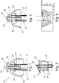
figure 1 , apersonal hearing device 10 is seen having afirst dome 16, areceiver 14 provided in ahousing 12 attached to the dome. The first dome is usually provided for attaching or fixing thedevice 10 inside an ear canal of a person. The first dome may be substantially sealing in the manner that sound and gas transport across the dome is impossible or at least impeded. Situations may exist where the first dome has a special channel, for example a small hole of any diameter in the range of 0.5-1mm, therein (in a thin sealing wall of the dome, for example, a flexible flap of the dome) for allowing sound with a small intensity of air to travel from one side to the other side of the dome. - The upper side in the dome is to be directed toward the ear drum of the person. The
speaker channel output 20 is provided in the upper portion and aspeaker channel 18 exists between the receiver 14 (output) and thespeaker channel output 20. - An
acoustic vent channel 22 is provided having avent channel opening 24. Theacoustic vent channel 22 may extend to an opening 22' outside of thehousing 14 on the lower side of the first dome. A vent of this type may have a valve configured to open and close the vent. This vent may be used for e.g. preventing the so-called occlusion effect. - A
separation member 26 is provided. Thesound channel 18 extends through the stem of the separation member to the speaker channel output which is provided on the upper side of the separation member. - The vent channel opening on the other hand is provided in the first dome or between the first dome and the separation member. It is seen that the separation member covers the vent channel opening when projected on to a plane perpendicular to the central axis A of the first dome. Often, the first dome, or at least an upper or outer surface thereof, will be symmetric, so that the central axis is a symmetry axis.
- The function of the separation member thus is to reduce transfer of sound output by the
speaker channel output 20 to thevent channel opening 24. - A purpose of the present device is to on the one side provide the
vent 22 to allow low frequency sound to exit the space between thedome 16 in the ear canal (for venting air between the dome and eardrum to outside of earcanal, in order to reduce the occlusion ) while, on the other side, to not have too much of the sound output by the speaker channel output escape the space between the speaker channel output and the ear drum through the vent 22 (to reduce the acoustical feedback). This is ensured, in this embodiment, by theseparation member 26 increasing the distance, which sound must take between the speaker channel output and the vent channel opening, compared to the same set-up where the separation member is omitted. Preferably, the sound from the speaker channel output has to travel at least 1mm in order to reach the vent channel opening. - In
figure 1 , theseparation member 26 is dome-shaped. However, a number of other shapes may be used. The overall purpose of the separation member is to increase the distance which sound must take from the speaker channel output to the vent channel opening. - Clearly, the shortest path will extend over an along convexities but simply across concavities of the structure.
- Another parameter which is operable to reduce the intensity of sound from the speaker channel output reaching the vent channel input is the angle which the sound must negotiate through this path, which influences the travelling distance of the sound, so that the distance may be increased by adjusting the angle.
-
Figure 8 is a figure from [M. D. Burkhard and R. M. Sachs, Sound Pressure in Insert Earphone Couplers and Real Ears, Journal of Speech and Hearing Research, vol. 20, pp 799-807 (1977)]: Surfaces of equal dip (antiresonance) frequency at corresponding observation points inside the volume of the 2CC simulator. - It is seen that sound emitted at 90 degrees to the sound output is attenuated within a much lower distance than sound output directly from the opening. Thus, the larger the angle which the sound must negotiate, the lower will the intensity be of the sound reaching the opening.
- In the embodiment of
figure 2 , it is seen that in addition to the actual distance to be covered by the sound, the sound has to firstly travel perpendicularly to the speaker channel opening and then turn 180 degrees, before it again turns 90 degrees to enter the vent channel opening. A total of 360 degrees thus is required for the sound to travel into the vent channel opening. - In this respect, the sound output of the opening is dependent on the angle of the sound relative to the opening - but not to the same degree to the direction of the sound passage leading to the opening.
- In
figure 1 , the speaker channel output has an opening which is, in the drawing, horizontal. The main direction of sound output by an opening is a direction perpendicular to a plane defined by the opening, such as the outer edge(s) thereof, if such a plane exists. - Naturally, the sound entering the vent channel opening will see the same effect. The larger the angle from the opening angle, the less sound will actually enter the channel.
- The complete angle which sound must negotiate between the speaker channel output and the vent channel opening thus is derived from that output direction and summed until the angle of the sound is along the direction of the vent channel opening.
- In
figure 1 , aslidable element 19 is illustrated which may open and close the opening 22'. Thisslidable element 19 may then form a component of a valve assembly for opening and closing the acoustic vent channel, for example using an electromechanical actuator. - The
speaker channel 18 may be partly formed by a relatively thin walled tube, such as ametal tube 1301 illustrated inFigure 13 with a wall thickness of 10-60µm, such as 25-35µm, which still provides sufficient stiffness. The inner radius of this tube may be 1-3mm, such as 1.5-2.4mm. - The
acoustic vent channel 22 may have a diameter of 2-4mm, as it still should fit inside an ear canal. Thischannel 22 may also be formed by a tube e.g. 1302 inFigure 13 , which may be metal or a polymer having a wall thickness of 0.05-0.3mm, such as around 0.1mm. Theinner radius 1303 of this tube may be 3.3mm, or another value in the range 2.2-4mm. Theexternal radius 1304 of this tube may be 3.5mm, or another value in the range 2.4-4.2mm. Aside venting opening 1305 may be provided, as described inEP 3471432 . - In
Figure 12 , a speaker channel known from the prior art is illustrated. Thetube 1202 forms a speaker channel with aninner radius 1202 of 1.4mm, andexternal radius 1203 of 2.5mm. The tube has plastic walls of 0.3mm thickness. -
Figure 2 illustrates a device as that infigure 1 but where thefirst dome 16 and the receiver have been removed for clarity. The straight upward arrow illustrates the sound path of sound from thereceiver 14 and the left, curved, downwardly directed arrow illustrates the sound path of thevent 22. The line above thedome 26 illustrates the path which sound from thesound outlet 20 must take to reach thevent channel opening 24. -
Figure 3 illustrates an embodiment similar to that offigure 1 . The same elements have the same reference numerals, and the difference is the presence of a protection member, 36, which may also be dome shaped, which is provided above or over thespeaker channel 18 to provide a wax protection. Then, the speaker channel outlet is now provided between theseparation member 26 and the preventingmember 36. The preventing member then may prevent ear wax from being forced into the speaker channel output when thedevice 10 is transported into the ear canal. -
Figure 4 illustrates an alternative embodiment with afirst dome 261 having aspeaker channel 181 with aspeaker channel outlet 201 and avent channel 221 with avent channel opening 241. The receiver etc. is not illustrated. - Foam may be provided inside any of the
speaker channel 18,acoustic vent channel 22, and/or thevent channel 221. The foam may include reticulated polyester or polyether polyurethane material. The foam material may have the porosity in the range 70-100 ppi (pores per inch), for example, 70, 75, 80, 85, 90 or 95 ppi. The foam may have a shape of a sleeve or tube or ring for positioning on a side of thetube 1302 inFigure 13 . - Even though both channels extend through the stem of the dome, they flare out at the upper end to allow the output and the outlet to have a minimum distance, 261, illustrated in
figure 5 , between them. In addition, it is seen that the directions of the openings also are directed away from each other so that the angle which must be negotiated by the sound is more than a certain threshold value, such as 30, 40, 50, 60, 70, 80, 90, 100, 110, 120, 130, 140, 150, 160, 170, or 180 degrees. - In the present embodiment, the opening and output are provided symmetrically around the central axis A. This is not a requirement.
- In
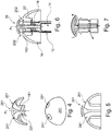
figure 6 , yet another embodiment is illustrated where the features in common withfigure 1 have the same numerals. - In the embodiment of
figure 6 , thesound channel 18 extends into a portion of thedome 16 via anopening 182 in the central sound channel. Thespeaker channel output 202 is provided below theseparation member 26 which, in this situation, does not have a central speaker channel output. - In the same manner, the vent channel extends from an opening 22' below the
dome 16 to thevent channel opening 242. The vent channel is not illustrated in the present cross section but exists in other cross sections. - The speaker channel output path and the vent path are seen in
figure 7 as well as the shortest path which the sound must take from the speaker channel output to the vent channel opening. - In
Figure 9 , it is illustrated that a medium spacing with a shortest distance between a speaker channel output and the acoustic vent channel opening provides a certain feedback reduction. The large spacing provides another feedback reduction. In an exemplary test measurement, a microphone signal is measured outside the earcanal, for example as by a typical BTE microphone. Another acoustic signal is measured by a second microphone near the eardrum. In a first test, a closed dome is provided with a very small distance between the speaker channel output and the vent channel opening. At a certain frequency, e.g. 3kHz, the difference between signals of both microphones approaches 50dB difference. The possible gain margin of the hearing aid will be reduced and will not function properly. With the medium and large distances between the speaker channel output and the vent channel opening, the BTE microphone can still measure external audio signals and the hearing device functions properly. -
Figure 10 illustrates an embodiment of a personal hearing device fully positioned in an earcanal. A volume can be seen between thedome 16 and the eardrum. The speaker provides the sound to this volume. The vent releases the air from this volume to reduce the occlusion, while the vent channel opening and the speaker channel output are separated and interface this volume. InFigure 11 , a personal hearing device is positioned at an earcanal. A similar volume can be seen as with reference toFigure 10 . -
Figure 14 illustrates a personal hearing device with a dome with an acoustic vent channel opening under a flap of the dome. The speaker outputs the sound through thespeaker channel 1405, with thespeaker channel output 1402. The dome has aflexible member 1401 for comfortably positioning a hearing device inside or at the earcanal. Theacoustical venting channel 1404 is provided, with theopening 1408 just outside the dome and toward the earcanal, and with anotheropening 1403 under thedome flap 1401. Thechannels separation 1409 between thespeaker channel output 1402 and the ventingchannel opening 1408 should be observed according to the present invention in order to reduce the feedback. Theseparation 1409 is provided through the angle of at least 5 degrees defined between the first and second directions. - The speaker channel and the venting channels may be also oriented sidewise as
Figures 6 and 7 . - Advantageously, a path length of the
venting channel 1404 should be as short as possible, in order to improve the acoustical venting performance, for example, the shorter and wider the venting channel provides a better acoustic bandwidth, as described inEuropean patent application number EP 17196716.9 EP3471432 . In order to provide a dome with such venting solution, thevent opening 1403 is provided as close to thedome flap 1401 as possible. - The dome may be mounted through a sleeve, plastic tube or in another way in a
position 1407 between theventing opening 1403 and the rest of the hearing device, e.g. between theopening 1403 and thespeaker housing 1410. InFigure 14 , it is illustrated that the dome is retained through a locking mechanism between the dome tube and the venting tube, for example, through asnap lock 1406. - The locking mechanism may require a hard material, while the
dome flap 1401 may be made from a softer material as a softer "umbrella" for a user comfort. Such dome may be made using a 2k molding. Such dome may be comfortable to a wearer, while also having a good retention on the hearing device. This also allows to positionretention ribs 1406 further away from theflap 1401, while theventing opening 1403 is positioned closer thedome flap 1401. - The
venting opening 1403 may be made by circular venting openings, e.g. as elements 22-1 in Figure 17 of European patent application published asEP3471432 . - Different structural elements of the receiver channel and venting channel may be combined and molded from the same material as the dome tube and stem.
Claims (14)
- A personal hearing device (10) for positioning at or in an ear canal, the device (10) comprising an outer housing (12), a dome (16) and a speaker (14) provided in the housing (12), where:- a speaker channel (18) is provided extending from the speaker (14) to a speaker channel output (20), the speaker channel output (20) being provided in or at one side of the dome (16),- an acoustic vent channel (22) is provided from a vent channel opening (24) in or at the one side of the dome (16) to outside of the housing (12),where the speaker channel output (20) and the vent channel opening (24) are positioned with a shortest distance of 1-5mm between them, and outside of the hearing device (10), characterised in that the speaker channel output (20) defines a first output direction, the vent channel opening (24) defines a second direction, and an angle of at least 5 degrees exists between the first and second directions.
- A personal hearing device (10) according to claim 1, where the vent channel (22) has a length of 1- 24mm, an average cross section of 0.28-19.6mm2 and forming a low pass filter with a roll-off frequency of at least 500Hz.
- A personal hearing device (10) according to claim 1 or 2, wherein- the first output direction defined by the speaker channel output (20) is provided within at least one first angle interval around a central axis of the dome (16), and- the second direction defined by the vent channel opening (24) is provided within at least one second angle interval around the central axis, and the first and second angle intervals do not overlap.
- A personal hearing device (10) according to claim 3, wherein the first and second angle intervals are provided with at least 90 degrees between them.
- A personal hearing device (10) according to any of the preceding claims, wherein the angle between the first and second directions is 10 degrees or more.
- A personal hearing device (10) according to any of the preceding claims, wherein a plane exists between the vent channel opening (24) and the speaker channel output (20), where the first output direction and the second direction of the speaker channel output (20) and the vent channel opening (24) are away from the plane.
- A personal hearing device (10) according to any of the preceding claims, wherein a shortest path, outside of the device (10) and from the speaker channel output (20) to the vent channel opening (24), has one or more bends, where a total sum of angles of the bend(s) is at least 180 degrees.
- A personal hearing device (10) according to any of the preceding claims, further comprising a separation member (26) positioned at the one side of the dome (16), the speaker channel output (20) and the vent channel opening (24) output being provided in the dome (16) or between the dome (16) and the separation member (26), the separation member (26) covering the speaker channel output (20) and the vent channel opening (24) when projected on to a plane perpendicular to a central axis of the dome (16).
- A personal hearing device (10) according to any of claims 1-7, wherein:- a separation member (26) is provided on the one side of the dome, the speaker channel (18) extending through the separation member (26),- the vent channel opening (24) is provided in the dome (16) or between the dome (16) and the separation member (26), and- the separation member (26) covers the vent channel opening (24) when the separation member (26) and the speaker channel output (20) are projected on to a plane perpendicular to a central axis of the dome (16).
- A personal hearing device (10) according to claim 9, wherein the speaker channel (18) extends along the central axis.
- A personal hearing device (10) according to claim 9 or 10, wherein the speaker channel (18) extends through a stem of the separation member (26).
- A personal hearing device (10) according to any of claims 9-11, further comprising a protection member (36), the speaker channel output (20) being provided in the separation member (26) or between the separation member (26) and the protection member (36), the protection member (36) covering the speaker channel output (20) when the protection member (36) and the speaker channel output (20) are projected on to the plane.
- A personal hearing device (10) according to any of claims 9-12, wherein the separation member (26) is circular symmetric around the central axis.
- A personal hearing device (10) according to any of the preceding claims, further comprising a valve assembly with an electromechanical actuator configured to open and close the acoustic vent channel (22).
Applications Claiming Priority (1)
| Application Number | Priority Date | Filing Date | Title |
|---|---|---|---|
| EP19169292 | 2019-04-15 |
Publications (2)
| Publication Number | Publication Date |
|---|---|
| EP3726855A1 EP3726855A1 (en) | 2020-10-21 |
| EP3726855B1 true EP3726855B1 (en) | 2021-09-01 |
Family
ID=66182443
Family Applications (1)
| Application Number | Title | Priority Date | Filing Date |
|---|---|---|---|
| EP20164608.0A Active EP3726855B1 (en) | 2019-04-15 | 2020-03-20 | A personal hearing device with a vent channel and acoustic separation |
Country Status (3)
| Country | Link |
|---|---|
| US (1) | US11197111B2 (en) |
| EP (1) | EP3726855B1 (en) |
| DK (1) | DK3726855T3 (en) |
Families Citing this family (6)
| Publication number | Priority date | Publication date | Assignee | Title |
|---|---|---|---|---|
| EP3860147B1 (en) | 2020-01-31 | 2023-06-07 | Sonion Nederland B.V. | An assembly comprising a sound generator and a sensor in a spout having a sound channel |
| US11570537B2 (en) * | 2020-08-31 | 2023-01-31 | Oticon A/S | Dome for hearing aids |
| DK202070805A1 (en) | 2020-11-30 | 2022-06-10 | Gn Hearing As | Earpiece for a hearing device, dome and earpiece part |
| US20230086021A1 (en) * | 2021-09-17 | 2023-03-23 | Apple Inc. | Dynamic valve for an electronic device |
| EP4199533A1 (en) * | 2021-12-17 | 2023-06-21 | Sonova AG | Earpiece for a hearing device |
| EP4254980A1 (en) * | 2022-03-31 | 2023-10-04 | GN Hearing A/S | Hearing device |
Family Cites Families (97)
| Publication number | Priority date | Publication date | Assignee | Title |
|---|---|---|---|---|
| NL1009544C2 (en) | 1998-07-02 | 2000-01-10 | Microtronic Nederland Bv | System consisting of a microphone and a preamp. |
| US7221769B1 (en) | 1998-09-24 | 2007-05-22 | Sonion Roskilde A/S | Hearing aid adapted for discrete operation |
| US7706561B2 (en) | 1999-04-06 | 2010-04-27 | Sonion Nederland B.V. | Electroacoustic transducer with a diaphragm and method for fixing a diaphragm in such transducer |
| NL1011733C1 (en) | 1999-04-06 | 2000-10-09 | Microtronic Nederland Bv | Electroacoustic transducer with a membrane and method for mounting a membrane in such a transducer. |
| NL1011778C1 (en) | 1999-04-13 | 2000-10-16 | Microtronic Nederland Bv | Microphone for a hearing aid and a hearing aid provided with such a microphone. |
| US6930259B1 (en) | 1999-06-10 | 2005-08-16 | Sonion A/S | Encoder |
| US6522762B1 (en) | 1999-09-07 | 2003-02-18 | Microtronic A/S | Silicon-based sensor system |
| AU2001268954A1 (en) | 2000-06-30 | 2002-01-14 | Sonionmicrotronic Nederland B.V. | A microphone assembly |
| US7181035B2 (en) | 2000-11-22 | 2007-02-20 | Sonion Nederland B.V. | Acoustical receiver housing for hearing aids |
| TW510139B (en) | 2001-01-26 | 2002-11-11 | Kirk Acoustics As | An electroacoustic transducer and a coil and a magnet circuit therefor |
| US6831577B1 (en) | 2001-02-02 | 2004-12-14 | Sonion A/S | Sigma delta modulator having enlarged dynamic range due to stabilized signal swing |
| AU2002237204A1 (en) | 2001-03-09 | 2002-09-24 | Techtronic A/S | An electret condensor microphone preamplifier that is insensitive to leakage currents at the input |
| EP1248496A3 (en) | 2001-04-04 | 2005-11-02 | Sonionmicrotronic Nederland B.V. | Aucoustic receiver having improved mechanical suspension |
| US7062058B2 (en) | 2001-04-18 | 2006-06-13 | Sonion Nederland B.V. | Cylindrical microphone having an electret assembly in the end cover |
| US7136496B2 (en) | 2001-04-18 | 2006-11-14 | Sonion Nederland B.V. | Electret assembly for a microphone having a backplate with improved charge stability |
| US6859542B2 (en) | 2001-05-31 | 2005-02-22 | Sonion Lyngby A/S | Method of providing a hydrophobic layer and a condenser microphone having such a layer |
| US7227968B2 (en) | 2001-06-25 | 2007-06-05 | Sonion Roskilde A/S | Expandsible Receiver Module |
| DE60238657D1 (en) | 2001-07-20 | 2011-02-03 | Sonion As | Switch / volume control for a hearing aid |
| US6788796B1 (en) | 2001-08-01 | 2004-09-07 | The Research Foundation Of The State University Of New York | Differential microphone |
| DE10141800C1 (en) * | 2001-08-27 | 2003-01-16 | Siemens Audiologische Technik | In-ear hearing aid has moulded plastics plug fitted into ear with active venting of auditory canal via control signal outside audible frequency range |
| US7239714B2 (en) | 2001-10-09 | 2007-07-03 | Sonion Nederland B.V. | Microphone having a flexible printed circuit board for mounting components |
| DE60208408T2 (en) | 2001-10-10 | 2006-09-28 | Sonion Roskilde A/S | DIGITAL POWDER PRODUCER |
| WO2003032345A1 (en) | 2001-10-10 | 2003-04-17 | Sonionmicrotronic A/S | A multifunctional switch |
| JP3768431B2 (en) * | 2001-10-31 | 2006-04-19 | スター精密株式会社 | Insertion type earphone |
| US7336794B2 (en) | 2001-11-30 | 2008-02-26 | Sonion A/S | High efficiency driver for miniature loudspeakers |
| KR20040081470A (en) | 2002-01-25 | 2004-09-21 | 소니온 호르젠스 에이/에스 | Flexible diaphragm with integrated coil |
| US7190803B2 (en) | 2002-04-09 | 2007-03-13 | Sonion Nederland Bv | Acoustic transducer having reduced thickness |
| US6888408B2 (en) | 2002-08-27 | 2005-05-03 | Sonion Tech A/S | Preamplifier for two terminal electret condenser microphones |
| US7072482B2 (en) | 2002-09-06 | 2006-07-04 | Sonion Nederland B.V. | Microphone with improved sound inlet port |
| US8280082B2 (en) | 2002-10-08 | 2012-10-02 | Sonion Nederland B.V. | Electret assembly for a microphone having a backplate with improved charge stability |
| US7292876B2 (en) | 2002-10-08 | 2007-11-06 | Sonion Nederland B.V. | Digital system bus for use in low power instruments such as hearing aids and listening devices |
| US7142682B2 (en) | 2002-12-20 | 2006-11-28 | Sonion Mems A/S | Silicon-based transducer for use in hearing instruments and listening devices |
| DK1434464T3 (en) | 2002-12-23 | 2008-08-11 | Sonion Roskilde As | Encapsulated receiver comprising an expandable member such as a balloon |
| US7008271B2 (en) | 2003-02-20 | 2006-03-07 | Sonion Roskilde A/S | Female connector assembly with a displaceable conductor |
| EP1455370B1 (en) | 2003-03-04 | 2006-06-07 | Sonion Roskilde A/S | Combined roller and push switch assembly |
| US7466835B2 (en) | 2003-03-18 | 2008-12-16 | Sonion A/S | Miniature microphone with balanced termination |
| DE10316287B3 (en) | 2003-04-09 | 2004-07-15 | Siemens Audiologische Technik Gmbh | Directional microphone for hearing aid having 2 acoustically coupled membranes each coupled to respective sound entry opening |
| DK1473970T3 (en) | 2003-05-01 | 2008-09-29 | Sonion Roskilde As | Miniature hearing aid insert module |
| US7012200B2 (en) | 2004-02-13 | 2006-03-14 | Sonion Roskilde A/S | Integrated volume control and switch assembly |
| EP1757161B1 (en) | 2004-05-14 | 2016-11-30 | Sonion Nederland B.V. | Dual diaphragm electroacoustic transducer |
| EP1599067B1 (en) | 2004-05-21 | 2013-05-01 | Epcos Pte Ltd | Detection and control of diaphragm collapse in condenser microphones |
| EP1613125A3 (en) | 2004-07-02 | 2008-10-22 | Sonion Nederland B.V. | Microphone assembly comprising magnetically activable element for signal switching and field indication |
| US7460681B2 (en) | 2004-07-20 | 2008-12-02 | Sonion Nederland B.V. | Radio frequency shielding for receivers within hearing aids and listening devices |
| EP1626612A3 (en) | 2004-08-11 | 2009-05-06 | Sonion Nederland B.V. | Hearing aid microphone mounting structure and method for mounting |
| DK1638366T3 (en) | 2004-09-20 | 2015-12-14 | Sonion Nederland Bv | microphone device |
| US7415121B2 (en) | 2004-10-29 | 2008-08-19 | Sonion Nederland B.V. | Microphone with internal damping |
| EP1653767A3 (en) | 2004-11-01 | 2008-11-19 | Sonion Nederland B.V. | Electro-acoustical transducer and transducer assembly |
| DK1853091T3 (en) | 2005-01-10 | 2011-10-24 | Sonion Nederland Bv | Hearing aid with miniature speaker |
| EP1880575A1 (en) | 2005-05-09 | 2008-01-23 | Knowles Electronics, LLC | Conjoined receiver and microphone assembly |
| EP1742506B1 (en) | 2005-07-06 | 2013-05-22 | Epcos Pte Ltd | Microphone assembly with P-type preamplifier input stage |
| EP1913793B1 (en) * | 2005-08-01 | 2010-10-13 | GN ReSound A/S | A hearing device with an open earpiece having a short vent |
| US7899203B2 (en) | 2005-09-15 | 2011-03-01 | Sonion Nederland B.V. | Transducers with improved viscous damping |
| DE602007005405D1 (en) | 2006-01-26 | 2010-05-06 | Sonion Mems As | Elastomer shield for miniature microphones |
| EP1852882A3 (en) | 2006-05-01 | 2009-07-29 | Sonion Roskilde A/S | A multi-functional control |
| US8170249B2 (en) | 2006-06-19 | 2012-05-01 | Sonion Nederland B.V. | Hearing aid having two receivers each amplifying a different frequency range |
| EP1895811B1 (en) | 2006-08-28 | 2016-06-08 | Sonion Nederland B.V. | Multiple receivers with a common acoustic spout |
| ATE530033T1 (en) | 2006-11-21 | 2011-11-15 | Sonion As | TWO-PIECE CONNECTOR ASSEMBLY |
| JP2010514172A (en) | 2006-12-22 | 2010-04-30 | パルス・エムイーエムエス・アンパルトセルスカブ | Microphone assembly using underfill agent with low coefficient of thermal expansion |
| US7995782B2 (en) | 2007-01-29 | 2011-08-09 | Siemens Hearing Instruments, Inc. | Combined receiver and ear-canal microphone assembly for a hearing instrument |
| EP1962551B1 (en) | 2007-02-20 | 2014-04-16 | Sonion Nederland B.V. | A moving armature receiver |
| US8391534B2 (en) | 2008-07-23 | 2013-03-05 | Asius Technologies, Llc | Inflatable ear device |
| US8160290B2 (en) | 2007-09-04 | 2012-04-17 | Sonion A/S | Electroacoustic transducer having a slotted terminal structure for connection to a flexible wire, and an assembly of the same |
| EP2046072A3 (en) | 2007-10-01 | 2009-11-04 | Sonion Nederland B.V. | A microphone assembly with a replaceable part |
| DK2071866T3 (en) | 2007-12-14 | 2017-07-24 | Sonion As | Removable earpiece sound system with spring control |
| US8189804B2 (en) | 2007-12-19 | 2012-05-29 | Sonion Nederland B.V. | Sound provider adapter to cancel out noise |
| US8259976B2 (en) | 2008-04-02 | 2012-09-04 | Sonion Nederland B.V. | Assembly comprising a sound emitter and two sound detectors |
| US8101876B2 (en) | 2008-04-22 | 2012-01-24 | Sonion Aps | Electro-mechanical pulse generator |
| DK2134107T3 (en) | 2008-06-11 | 2013-10-14 | Sonion Nederland Bv | Method of operating a hearing aid with improved ventilation |
| EP2166779B1 (en) | 2008-09-18 | 2019-05-22 | Sonion Nederland B.V. | An apparatus for outputting sound comprising multiple receivers and a common output channel |
| US8526651B2 (en) | 2010-01-25 | 2013-09-03 | Sonion Nederland Bv | Receiver module for inflating a membrane in an ear device |
| US8313336B2 (en) | 2010-02-01 | 2012-11-20 | Sonion A/S | Assembly comprising a male and a female plug member, a male plug member and a female plug member |
| US7946890B1 (en) | 2010-02-02 | 2011-05-24 | Sonion A/S | Adapter for an electronic assembly |
| US20110274296A1 (en) * | 2010-05-05 | 2011-11-10 | Victor Kingsun Wai | Ear Tip Method and Apparatus |
| US20110299708A1 (en) | 2010-06-07 | 2011-12-08 | Sonion A/S | Method of forming a connector for a hearing aid |
| EP2393311A1 (en) | 2010-06-07 | 2011-12-07 | Sonion A/S | A cerumen filter for a hearing aid |
| DK2408221T3 (en) | 2010-07-16 | 2017-01-16 | Sonion Nederland Bv | Hearing aid |
| US8712084B2 (en) | 2010-12-07 | 2014-04-29 | Sonion Nederland Bv | Motor assembly |
| DK3048810T3 (en) | 2010-12-14 | 2019-06-11 | Sonion Nederland Bv | Multi-layer luminaire for a movable luminaire receiver |
| EP2469705B1 (en) | 2010-12-21 | 2015-12-02 | Sonion Nederland B.V. | Generation of a supply voltage from output of a class-D audio amplifier |
| DK2503792T3 (en) | 2011-03-21 | 2018-08-20 | Sonion Nederland Bv | Speaker device with movable luminaire with vibration suppression |
| CN103748903B (en) | 2011-06-01 | 2017-02-22 | 菲泰克系统有限公司 | In-ear device incorporating active noise reduction |
| EP2552128A1 (en) | 2011-07-29 | 2013-01-30 | Sonion Nederland B.V. | A dual cartridge directional microphone |
| US9055380B2 (en) | 2011-11-28 | 2015-06-09 | Sonion Nederland B.V. | Method for producing a tube for a hearing aid |
| DK2608576T3 (en) | 2011-12-21 | 2020-03-30 | Sonion Nederland Bv | An apparatus and a method for providing sound |
| US8971554B2 (en) | 2011-12-22 | 2015-03-03 | Sonion Nederland Bv | Hearing aid with a sensor for changing power state of the hearing aid |
| US9313568B2 (en) * | 2013-07-23 | 2016-04-12 | Chicago Custom Acoustics, Inc. | Custom earphone with dome in the canal |
| DK3269153T3 (en) * | 2015-03-09 | 2019-07-15 | Sonova Ag | TRANSITION HEARING DEVICES WITH IMPROVED SEALS |
| EP3342749A3 (en) | 2016-12-30 | 2018-09-12 | Sonion Nederland B.V. | Micro-electromechanical transducer |
| US10560767B2 (en) | 2017-09-04 | 2020-02-11 | Sonion Nederland B.V. | Sound generator, a shielding and a spout |
| GB201714956D0 (en) * | 2017-09-18 | 2017-11-01 | Sonova Ag | Hearing device with adjustable venting |
| US10805746B2 (en) | 2017-10-16 | 2020-10-13 | Sonion Nederland B.V. | Valve, a transducer comprising a valve, a hearing device and a method |
| CN109672967B (en) | 2017-10-16 | 2021-09-17 | 声扬荷兰有限公司 | Personal hearing device |
| US10869119B2 (en) | 2017-10-16 | 2020-12-15 | Sonion Nederland B.V. | Sound channel element with a valve and a transducer with the sound channel element |
| DE102018107195B3 (en) * | 2018-02-05 | 2019-02-14 | Paul Gregor Junke | Universal silicone soft adapter for hearing aids |
| EP3525490A1 (en) * | 2018-02-13 | 2019-08-14 | Oticon A/s | An in-the-ear hearing aid device, a hearing aid, and an electro-acoustic transducer |
| EP3467457B1 (en) | 2018-04-30 | 2022-07-20 | Sonion Nederland B.V. | Vibration sensor |
| US11184697B2 (en) * | 2019-01-07 | 2021-11-23 | Team Ip Holdings, Llc | Conformable sealing eartip |
-
2020
- 2020-03-20 DK DK20164608.0T patent/DK3726855T3/en active
- 2020-03-20 EP EP20164608.0A patent/EP3726855B1/en active Active
- 2020-04-15 US US16/849,330 patent/US11197111B2/en active Active
Also Published As
| Publication number | Publication date |
|---|---|
| EP3726855A1 (en) | 2020-10-21 |
| US11197111B2 (en) | 2021-12-07 |
| DK3726855T3 (en) | 2021-11-15 |
| US20200329321A1 (en) | 2020-10-15 |
Similar Documents
| Publication | Publication Date | Title |
|---|---|---|
| EP3726855B1 (en) | A personal hearing device with a vent channel and acoustic separation | |
| US10945084B2 (en) | Personal hearing device | |
| US20200068283A1 (en) | In-ear headphones with an ergonomic cushion and an ergonomic cushion thereof | |
| US9185504B2 (en) | Dynamic pressure vent for canal hearing devices | |
| CN107950034B (en) | Noise reduction for in-ear headphones | |
| US20190208301A1 (en) | Audio device with acoustic valve | |
| US11882408B2 (en) | Earpiece with canal microphone, ambient microphone and receiver | |
| CN113271512A (en) | Ear canal type earphone with pressure balance structure | |
| US11234085B2 (en) | Earpieces and related articles and devices | |
| JP2009500926A (en) | Hearing aids and earpieces for hearing aids | |
| EP3637799B1 (en) | Hearing device comprising a housing with a venting passage | |
| JP4279306B2 (en) | hearing aid | |
| US20110249855A1 (en) | Earphone | |
| US10972822B2 (en) | Headphones with an ergonomic cushion and an ergonomic cushion thereof | |
| EP3334179B1 (en) | Hearing aid with an extended dome | |
| US9961458B1 (en) | Hearing aid sleeve | |
| US11178497B2 (en) | In-ear receiver | |
| CN114584885A (en) | Hearing device earpiece with angled microphone/receiver | |
| US11252503B2 (en) | Assembly comprising a sensor in a spout | |
| CN209002221U (en) | Hearing aids | |
| US11729560B1 (en) | Battery compartment of a hearing device configured to inhibit the ingress of debris into the battery compartment | |
| US20240080604A1 (en) | Acoustic vent and protective membrane | |
| US20240080603A1 (en) | Acoustic vent and protective membrane | |
| EP4254985A1 (en) | A hearing device | |
| CN117528309A (en) | Ear pad or ear mould for earphone and earphone with ear pad or ear mould |
Legal Events
| Date | Code | Title | Description |
|---|---|---|---|
| PUAI | Public reference made under article 153(3) epc to a published international application that has entered the european phase |
Free format text: ORIGINAL CODE: 0009012 |
|
| STAA | Information on the status of an ep patent application or granted ep patent |
Free format text: STATUS: THE APPLICATION HAS BEEN PUBLISHED |
|
| AK | Designated contracting states |
Kind code of ref document: A1 Designated state(s): AL AT BE BG CH CY CZ DE DK EE ES FI FR GB GR HR HU IE IS IT LI LT LU LV MC MK MT NL NO PL PT RO RS SE SI SK SM TR |
|
| AX | Request for extension of the european patent |
Extension state: BA ME |
|
| STAA | Information on the status of an ep patent application or granted ep patent |
Free format text: STATUS: REQUEST FOR EXAMINATION WAS MADE |
|
| 17P | Request for examination filed |
Effective date: 20201104 |
|
| RBV | Designated contracting states (corrected) |
Designated state(s): AL AT BE BG CH CY CZ DE DK EE ES FI FR GB GR HR HU IE IS IT LI LT LU LV MC MK MT NL NO PL PT RO RS SE SI SK SM TR |
|
| GRAP | Despatch of communication of intention to grant a patent |
Free format text: ORIGINAL CODE: EPIDOSNIGR1 |
|
| STAA | Information on the status of an ep patent application or granted ep patent |
Free format text: STATUS: GRANT OF PATENT IS INTENDED |
|
| GRAJ | Information related to disapproval of communication of intention to grant by the applicant or resumption of examination proceedings by the epo deleted |
Free format text: ORIGINAL CODE: EPIDOSDIGR1 |
|
| STAA | Information on the status of an ep patent application or granted ep patent |
Free format text: STATUS: REQUEST FOR EXAMINATION WAS MADE |
|
| INTG | Intention to grant announced |
Effective date: 20210331 |
|
| GRAP | Despatch of communication of intention to grant a patent |
Free format text: ORIGINAL CODE: EPIDOSNIGR1 |
|
| STAA | Information on the status of an ep patent application or granted ep patent |
Free format text: STATUS: GRANT OF PATENT IS INTENDED |
|
| INTC | Intention to grant announced (deleted) | ||
| INTG | Intention to grant announced |
Effective date: 20210518 |
|
| GRAJ | Information related to disapproval of communication of intention to grant by the applicant or resumption of examination proceedings by the epo deleted |
Free format text: ORIGINAL CODE: EPIDOSDIGR1 |
|
| STAA | Information on the status of an ep patent application or granted ep patent |
Free format text: STATUS: REQUEST FOR EXAMINATION WAS MADE |
|
| GRAP | Despatch of communication of intention to grant a patent |
Free format text: ORIGINAL CODE: EPIDOSNIGR1 |
|
| STAA | Information on the status of an ep patent application or granted ep patent |
Free format text: STATUS: GRANT OF PATENT IS INTENDED |
|
| GRAS | Grant fee paid |
Free format text: ORIGINAL CODE: EPIDOSNIGR3 |
|
| INTC | Intention to grant announced (deleted) | ||
| GRAA | (expected) grant |
Free format text: ORIGINAL CODE: 0009210 |
|
| STAA | Information on the status of an ep patent application or granted ep patent |
Free format text: STATUS: THE PATENT HAS BEEN GRANTED |
|
| INTG | Intention to grant announced |
Effective date: 20210712 |
|
| AK | Designated contracting states |
Kind code of ref document: B1 Designated state(s): AL AT BE BG CH CY CZ DE DK EE ES FI FR GB GR HR HU IE IS IT LI LT LU LV MC MK MT NL NO PL PT RO RS SE SI SK SM TR |
|
| REG | Reference to a national code |
Ref country code: GB Ref legal event code: FG4D |
|
| REG | Reference to a national code |
Ref country code: CH Ref legal event code: EP Ref country code: AT Ref legal event code: REF Ref document number: 1427526 Country of ref document: AT Kind code of ref document: T Effective date: 20210915 |
|
| REG | Reference to a national code |
Ref country code: DE Ref legal event code: R096 Ref document number: 602020000468 Country of ref document: DE |
|
| REG | Reference to a national code |
Ref country code: IE Ref legal event code: FG4D |
|
| REG | Reference to a national code |
Ref country code: DK Ref legal event code: T3 Effective date: 20211111 |
|
| REG | Reference to a national code |
Ref country code: LT Ref legal event code: MG9D |
|
| REG | Reference to a national code |
Ref country code: NL Ref legal event code: MP Effective date: 20210901 |
|
| PG25 | Lapsed in a contracting state [announced via postgrant information from national office to epo] |
Ref country code: FI Free format text: LAPSE BECAUSE OF FAILURE TO SUBMIT A TRANSLATION OF THE DESCRIPTION OR TO PAY THE FEE WITHIN THE PRESCRIBED TIME-LIMIT Effective date: 20210901 Ref country code: HR Free format text: LAPSE BECAUSE OF FAILURE TO SUBMIT A TRANSLATION OF THE DESCRIPTION OR TO PAY THE FEE WITHIN THE PRESCRIBED TIME-LIMIT Effective date: 20210901 Ref country code: NO Free format text: LAPSE BECAUSE OF FAILURE TO SUBMIT A TRANSLATION OF THE DESCRIPTION OR TO PAY THE FEE WITHIN THE PRESCRIBED TIME-LIMIT Effective date: 20211201 Ref country code: LT Free format text: LAPSE BECAUSE OF FAILURE TO SUBMIT A TRANSLATION OF THE DESCRIPTION OR TO PAY THE FEE WITHIN THE PRESCRIBED TIME-LIMIT Effective date: 20210901 Ref country code: BG Free format text: LAPSE BECAUSE OF FAILURE TO SUBMIT A TRANSLATION OF THE DESCRIPTION OR TO PAY THE FEE WITHIN THE PRESCRIBED TIME-LIMIT Effective date: 20211201 Ref country code: RS Free format text: LAPSE BECAUSE OF FAILURE TO SUBMIT A TRANSLATION OF THE DESCRIPTION OR TO PAY THE FEE WITHIN THE PRESCRIBED TIME-LIMIT Effective date: 20210901 Ref country code: SE Free format text: LAPSE BECAUSE OF FAILURE TO SUBMIT A TRANSLATION OF THE DESCRIPTION OR TO PAY THE FEE WITHIN THE PRESCRIBED TIME-LIMIT Effective date: 20210901 Ref country code: ES Free format text: LAPSE BECAUSE OF FAILURE TO SUBMIT A TRANSLATION OF THE DESCRIPTION OR TO PAY THE FEE WITHIN THE PRESCRIBED TIME-LIMIT Effective date: 20210901 |
|
| REG | Reference to a national code |
Ref country code: AT Ref legal event code: MK05 Ref document number: 1427526 Country of ref document: AT Kind code of ref document: T Effective date: 20210901 |
|
| PG25 | Lapsed in a contracting state [announced via postgrant information from national office to epo] |
Ref country code: PL Free format text: LAPSE BECAUSE OF FAILURE TO SUBMIT A TRANSLATION OF THE DESCRIPTION OR TO PAY THE FEE WITHIN THE PRESCRIBED TIME-LIMIT Effective date: 20210901 Ref country code: LV Free format text: LAPSE BECAUSE OF FAILURE TO SUBMIT A TRANSLATION OF THE DESCRIPTION OR TO PAY THE FEE WITHIN THE PRESCRIBED TIME-LIMIT Effective date: 20210901 Ref country code: GR Free format text: LAPSE BECAUSE OF FAILURE TO SUBMIT A TRANSLATION OF THE DESCRIPTION OR TO PAY THE FEE WITHIN THE PRESCRIBED TIME-LIMIT Effective date: 20211202 |
|
| PG25 | Lapsed in a contracting state [announced via postgrant information from national office to epo] |
Ref country code: AT Free format text: LAPSE BECAUSE OF FAILURE TO SUBMIT A TRANSLATION OF THE DESCRIPTION OR TO PAY THE FEE WITHIN THE PRESCRIBED TIME-LIMIT Effective date: 20210901 |
|
| PG25 | Lapsed in a contracting state [announced via postgrant information from national office to epo] |
Ref country code: IS Free format text: LAPSE BECAUSE OF FAILURE TO SUBMIT A TRANSLATION OF THE DESCRIPTION OR TO PAY THE FEE WITHIN THE PRESCRIBED TIME-LIMIT Effective date: 20220101 Ref country code: SM Free format text: LAPSE BECAUSE OF FAILURE TO SUBMIT A TRANSLATION OF THE DESCRIPTION OR TO PAY THE FEE WITHIN THE PRESCRIBED TIME-LIMIT Effective date: 20210901 Ref country code: SK Free format text: LAPSE BECAUSE OF FAILURE TO SUBMIT A TRANSLATION OF THE DESCRIPTION OR TO PAY THE FEE WITHIN THE PRESCRIBED TIME-LIMIT Effective date: 20210901 Ref country code: RO Free format text: LAPSE BECAUSE OF FAILURE TO SUBMIT A TRANSLATION OF THE DESCRIPTION OR TO PAY THE FEE WITHIN THE PRESCRIBED TIME-LIMIT Effective date: 20210901 Ref country code: PT Free format text: LAPSE BECAUSE OF FAILURE TO SUBMIT A TRANSLATION OF THE DESCRIPTION OR TO PAY THE FEE WITHIN THE PRESCRIBED TIME-LIMIT Effective date: 20220103 Ref country code: NL Free format text: LAPSE BECAUSE OF FAILURE TO SUBMIT A TRANSLATION OF THE DESCRIPTION OR TO PAY THE FEE WITHIN THE PRESCRIBED TIME-LIMIT Effective date: 20210901 Ref country code: EE Free format text: LAPSE BECAUSE OF FAILURE TO SUBMIT A TRANSLATION OF THE DESCRIPTION OR TO PAY THE FEE WITHIN THE PRESCRIBED TIME-LIMIT Effective date: 20210901 Ref country code: CZ Free format text: LAPSE BECAUSE OF FAILURE TO SUBMIT A TRANSLATION OF THE DESCRIPTION OR TO PAY THE FEE WITHIN THE PRESCRIBED TIME-LIMIT Effective date: 20210901 Ref country code: AL Free format text: LAPSE BECAUSE OF FAILURE TO SUBMIT A TRANSLATION OF THE DESCRIPTION OR TO PAY THE FEE WITHIN THE PRESCRIBED TIME-LIMIT Effective date: 20210901 |
|
| REG | Reference to a national code |
Ref country code: DE Ref legal event code: R097 Ref document number: 602020000468 Country of ref document: DE |
|
| PLBE | No opposition filed within time limit |
Free format text: ORIGINAL CODE: 0009261 |
|
| STAA | Information on the status of an ep patent application or granted ep patent |
Free format text: STATUS: NO OPPOSITION FILED WITHIN TIME LIMIT |
|
| PG25 | Lapsed in a contracting state [announced via postgrant information from national office to epo] |
Ref country code: IT Free format text: LAPSE BECAUSE OF FAILURE TO SUBMIT A TRANSLATION OF THE DESCRIPTION OR TO PAY THE FEE WITHIN THE PRESCRIBED TIME-LIMIT Effective date: 20210901 |
|
| 26N | No opposition filed |
Effective date: 20220602 |
|
| PG25 | Lapsed in a contracting state [announced via postgrant information from national office to epo] |
Ref country code: SI Free format text: LAPSE BECAUSE OF FAILURE TO SUBMIT A TRANSLATION OF THE DESCRIPTION OR TO PAY THE FEE WITHIN THE PRESCRIBED TIME-LIMIT Effective date: 20210901 |
|
| PG25 | Lapsed in a contracting state [announced via postgrant information from national office to epo] |
Ref country code: MC Free format text: LAPSE BECAUSE OF FAILURE TO SUBMIT A TRANSLATION OF THE DESCRIPTION OR TO PAY THE FEE WITHIN THE PRESCRIBED TIME-LIMIT Effective date: 20210901 |
|
| REG | Reference to a national code |
Ref country code: BE Ref legal event code: MM Effective date: 20220331 |
|
| PG25 | Lapsed in a contracting state [announced via postgrant information from national office to epo] |
Ref country code: LU Free format text: LAPSE BECAUSE OF NON-PAYMENT OF DUE FEES Effective date: 20220320 Ref country code: IE Free format text: LAPSE BECAUSE OF NON-PAYMENT OF DUE FEES Effective date: 20220320 |
|
| PG25 | Lapsed in a contracting state [announced via postgrant information from national office to epo] |
Ref country code: BE Free format text: LAPSE BECAUSE OF NON-PAYMENT OF DUE FEES Effective date: 20220331 |
|
| PGFP | Annual fee paid to national office [announced via postgrant information from national office to epo] |
Ref country code: FR Payment date: 20230221 Year of fee payment: 4 Ref country code: DK Payment date: 20230314 Year of fee payment: 4 |
|
| PGFP | Annual fee paid to national office [announced via postgrant information from national office to epo] |
Ref country code: DE Payment date: 20230207 Year of fee payment: 4 |
|
| PGFP | Annual fee paid to national office [announced via postgrant information from national office to epo] |
Ref country code: CH Payment date: 20230401 Year of fee payment: 4 |