EP0969542A1 - Battery - Google Patents
Battery Download PDFInfo
- Publication number
- EP0969542A1 EP0969542A1 EP98900705A EP98900705A EP0969542A1 EP 0969542 A1 EP0969542 A1 EP 0969542A1 EP 98900705 A EP98900705 A EP 98900705A EP 98900705 A EP98900705 A EP 98900705A EP 0969542 A1 EP0969542 A1 EP 0969542A1
- Authority
- EP
- European Patent Office
- Prior art keywords
- adhesive resin
- battery
- filler
- electrodes
- electrode
- Prior art date
- Legal status (The legal status is an assumption and is not a legal conclusion. Google has not performed a legal analysis and makes no representation as to the accuracy of the status listed.)
- Granted
Links
Images


Classifications
-
- H—ELECTRICITY
- H01—ELECTRIC ELEMENTS
- H01M—PROCESSES OR MEANS, e.g. BATTERIES, FOR THE DIRECT CONVERSION OF CHEMICAL ENERGY INTO ELECTRICAL ENERGY
- H01M10/00—Secondary cells; Manufacture thereof
- H01M10/05—Accumulators with non-aqueous electrolyte
- H01M10/058—Construction or manufacture
-
- H—ELECTRICITY
- H01—ELECTRIC ELEMENTS
- H01M—PROCESSES OR MEANS, e.g. BATTERIES, FOR THE DIRECT CONVERSION OF CHEMICAL ENERGY INTO ELECTRICAL ENERGY
- H01M10/00—Secondary cells; Manufacture thereof
- H01M10/05—Accumulators with non-aqueous electrolyte
-
- H—ELECTRICITY
- H01—ELECTRIC ELEMENTS
- H01M—PROCESSES OR MEANS, e.g. BATTERIES, FOR THE DIRECT CONVERSION OF CHEMICAL ENERGY INTO ELECTRICAL ENERGY
- H01M50/00—Constructional details or processes of manufacture of the non-active parts of electrochemical cells other than fuel cells, e.g. hybrid cells
- H01M50/40—Separators; Membranes; Diaphragms; Spacing elements inside cells
- H01M50/409—Separators, membranes or diaphragms characterised by the material
- H01M50/443—Particulate material
-
- H—ELECTRICITY
- H01—ELECTRIC ELEMENTS
- H01M—PROCESSES OR MEANS, e.g. BATTERIES, FOR THE DIRECT CONVERSION OF CHEMICAL ENERGY INTO ELECTRICAL ENERGY
- H01M10/00—Secondary cells; Manufacture thereof
- H01M10/04—Construction or manufacture in general
- H01M10/0436—Small-sized flat cells or batteries for portable equipment
-
- H—ELECTRICITY
- H01—ELECTRIC ELEMENTS
- H01M—PROCESSES OR MEANS, e.g. BATTERIES, FOR THE DIRECT CONVERSION OF CHEMICAL ENERGY INTO ELECTRICAL ENERGY
- H01M10/00—Secondary cells; Manufacture thereof
- H01M10/05—Accumulators with non-aqueous electrolyte
- H01M10/056—Accumulators with non-aqueous electrolyte characterised by the materials used as electrolytes, e.g. mixed inorganic/organic electrolytes
-
- H—ELECTRICITY
- H01—ELECTRIC ELEMENTS
- H01M—PROCESSES OR MEANS, e.g. BATTERIES, FOR THE DIRECT CONVERSION OF CHEMICAL ENERGY INTO ELECTRICAL ENERGY
- H01M50/00—Constructional details or processes of manufacture of the non-active parts of electrochemical cells other than fuel cells, e.g. hybrid cells
- H01M50/40—Separators; Membranes; Diaphragms; Spacing elements inside cells
- H01M50/409—Separators, membranes or diaphragms characterised by the material
- H01M50/411—Organic material
- H01M50/414—Synthetic resins, e.g. thermoplastics or thermosetting resins
- H01M50/417—Polyolefins
-
- H—ELECTRICITY
- H01—ELECTRIC ELEMENTS
- H01M—PROCESSES OR MEANS, e.g. BATTERIES, FOR THE DIRECT CONVERSION OF CHEMICAL ENERGY INTO ELECTRICAL ENERGY
- H01M50/00—Constructional details or processes of manufacture of the non-active parts of electrochemical cells other than fuel cells, e.g. hybrid cells
- H01M50/40—Separators; Membranes; Diaphragms; Spacing elements inside cells
- H01M50/409—Separators, membranes or diaphragms characterised by the material
- H01M50/411—Organic material
-
- H—ELECTRICITY
- H01—ELECTRIC ELEMENTS
- H01M—PROCESSES OR MEANS, e.g. BATTERIES, FOR THE DIRECT CONVERSION OF CHEMICAL ENERGY INTO ELECTRICAL ENERGY
- H01M50/00—Constructional details or processes of manufacture of the non-active parts of electrochemical cells other than fuel cells, e.g. hybrid cells
- H01M50/40—Separators; Membranes; Diaphragms; Spacing elements inside cells
- H01M50/409—Separators, membranes or diaphragms characterised by the material
- H01M50/431—Inorganic material
-
- H—ELECTRICITY
- H01—ELECTRIC ELEMENTS
- H01M—PROCESSES OR MEANS, e.g. BATTERIES, FOR THE DIRECT CONVERSION OF CHEMICAL ENERGY INTO ELECTRICAL ENERGY
- H01M50/00—Constructional details or processes of manufacture of the non-active parts of electrochemical cells other than fuel cells, e.g. hybrid cells
- H01M50/40—Separators; Membranes; Diaphragms; Spacing elements inside cells
- H01M50/46—Separators, membranes or diaphragms characterised by their combination with electrodes
- H01M50/461—Separators, membranes or diaphragms characterised by their combination with electrodes with adhesive layers between electrodes and separators
-
- H—ELECTRICITY
- H01—ELECTRIC ELEMENTS
- H01M—PROCESSES OR MEANS, e.g. BATTERIES, FOR THE DIRECT CONVERSION OF CHEMICAL ENERGY INTO ELECTRICAL ENERGY
- H01M6/00—Primary cells; Manufacture thereof
- H01M6/04—Cells with aqueous electrolyte
- H01M6/06—Dry cells, i.e. cells wherein the electrolyte is rendered non-fluid
- H01M6/10—Dry cells, i.e. cells wherein the electrolyte is rendered non-fluid with wound or folded electrodes
-
- H—ELECTRICITY
- H01—ELECTRIC ELEMENTS
- H01M—PROCESSES OR MEANS, e.g. BATTERIES, FOR THE DIRECT CONVERSION OF CHEMICAL ENERGY INTO ELECTRICAL ENERGY
- H01M6/00—Primary cells; Manufacture thereof
- H01M6/40—Printed batteries, e.g. thin film batteries
-
- Y—GENERAL TAGGING OF NEW TECHNOLOGICAL DEVELOPMENTS; GENERAL TAGGING OF CROSS-SECTIONAL TECHNOLOGIES SPANNING OVER SEVERAL SECTIONS OF THE IPC; TECHNICAL SUBJECTS COVERED BY FORMER USPC CROSS-REFERENCE ART COLLECTIONS [XRACs] AND DIGESTS
- Y02—TECHNOLOGIES OR APPLICATIONS FOR MITIGATION OR ADAPTATION AGAINST CLIMATE CHANGE
- Y02E—REDUCTION OF GREENHOUSE GAS [GHG] EMISSIONS, RELATED TO ENERGY GENERATION, TRANSMISSION OR DISTRIBUTION
- Y02E60/00—Enabling technologies; Technologies with a potential or indirect contribution to GHG emissions mitigation
- Y02E60/10—Energy storage using batteries
-
- Y—GENERAL TAGGING OF NEW TECHNOLOGICAL DEVELOPMENTS; GENERAL TAGGING OF CROSS-SECTIONAL TECHNOLOGIES SPANNING OVER SEVERAL SECTIONS OF THE IPC; TECHNICAL SUBJECTS COVERED BY FORMER USPC CROSS-REFERENCE ART COLLECTIONS [XRACs] AND DIGESTS
- Y02—TECHNOLOGIES OR APPLICATIONS FOR MITIGATION OR ADAPTATION AGAINST CLIMATE CHANGE
- Y02P—CLIMATE CHANGE MITIGATION TECHNOLOGIES IN THE PRODUCTION OR PROCESSING OF GOODS
- Y02P70/00—Climate change mitigation technologies in the production process for final industrial or consumer products
- Y02P70/50—Manufacturing or production processes characterised by the final manufactured product
Definitions
- This invention relates to a battery and, more particularly, to a battery structure that realizes a light, compact and thin battery having a high discharging capacity at a high current density and satisfactory cycle characteristics.
- Batteries have been used long as a main power source or a backup power source for a variety of equipment.
- the demand for batteries has recently been increasing with the development of portable electronic equipment, such as cellular phones and portable personal computers.
- Primary batteries and secondary batteries are available according to use.
- secondary batteries having great convenience, high performance batteries such as lithium ion secondary batteries and nickel-hydrogen batteries have been attracting attention.
- the present invention will hereinafter be explained by referring to lithium ion secondary batteries the demand of which has been steeply increasing for use in portable electronic equipment.
- Conventional lithium ion secondary batteries comprise a battery body that is a cylindrical roll of an electrode body or a stack of rectangular electrode bodies, the electrode body being composed of a positive electrode, a negative electrode, and a separator that is interposed between the two electrodes to serve for insulation and retention of an electrolyte.
- the battery body is put in a metal-made case so that the positive electrode, the negative electrode and the separator can be brought into intimate contact by the pressure of the case thereby to maintain the contact between each electrode and the separator.
- An electrical contact can be maintained by putting the battery body in a metal-made case, but there is a problem that the case, being made of metal, increases the weight of the battery. Moreover, it is difficult to make a thin metal case. Difficulty in making a thin case has been a great obstacle to fulfillment of the demand for batteries to be used in compact portable equipment.
- U.S. Patent 5,437,692 discloses a structure in which a lithium ion-conducting polymer is used as an ion conducting layer, and a positive electrode and a negative electrode are joined to the ion-conducting layer with an adhesive layer containing a lithium compound.
- the inventors of the present invention previously proposed in Japanese Patent Application No. 8-338240 a battery structure requiring no metal-made rigid case and a process for producing the same, in which a positive electrode and a negative electrode are previously joined to a separator with an adhesive resin.
- the method comprising joining a positive and a negative electrode to a lithium ion-conducting polymer with an adhesive layer containing a lithium compound is disadvantageous in that the adhesive layer attains weak adhesion and becomes considerable resistance to ion conduction.
- the method comprising previously joining a positive and a negative electrode to a separator with an adhesive resin has made it feasible to maintain an electrical contact among them without imposing an external force but involves a problem that resistance between electrodes (i.e., a positive electrode and a negative electrode) increases because of the existence of not only the separator but the adhesive resin between the electrodes.
- Direct bonding of electrodes is a conceivable method. In this case, it is necessary to secure both ion conduction and electron insulation between electrodes that ought to be undertaken by a conventional ion-conducting polymer or separator, and yet to join the electrodes firmly.
- the conventional ion-conducting polymer has weak adhesive strength
- the conventional adhesive resin joining electrodes and a separator has high adhesive strength but tends to deteriorate ion conductivity.
- electrodes have their surfaces smoothed by pressing but still have unevenness of several microns to form vacancies where a separator and the electrodes are not in contact.
- the vacancies that should have been filled with an electrolyte may get starved of the electrolyte, which depends on the amount of the electrolyte supplied and the condition of use of the battery. Starvation of the electrolyte leads to an increase of internal resistivity of the battery and reductions in battery characteristics.
- the present invention has been reached, aiming at settlement of the above-described problems. It is an object of the invention to provide a light, compact and thin battery in which a positive and a negative electrode are joined firmly to maintain the adhesive strength while securing both electron insulation and ion conduction between electrodes and decreasing resistance between electrodes, i.e., internal resistance of a battery, to improve battery characteristics.
- a first battery according to the invention comprises a battery body having a positive and a negative electrode containing an active material, an electrolytic solution containing an electrolyte, and an adhesive resin layer which is interposed in between the positive electrode and the negative electrode and is joined to at least one of the positive and the negative electrodes, wherein the adhesive resin layer comprises at least one layer and contains fillers.
- the adhesive resin layer comprises at least one layer and contains fillers.
- a second battery according to the invention is the above-described first battery, wherein the electrolyte is an organic electrolyte containing lithium ions.
- This mode when applied to lithium ion secondary batteries which are required to have reduced weight and thickness, provides a high performance compact battery.
- a third battery according to the invention is the above-described first battery, wherein the average particle size of the filler is equal to or smaller than the particle size of the active material of the positive and negative electrodes.
- a fourth battery according to the invention is the above-described first battery, wherein the average particle size of the filler is 1 ⁇ m or smaller.
- the filler manifests a proper thickening effect for the adhesive resin solution to make the adhesive resin solution hardly absorbable by the active material thereby securing necessary adhesive strength. Further, the filler makes the adhesive resin layer porous to improve ion conductivity thereby providing satisfactory battery characteristics.
- a fifth battery according to the invention is the above-described first battery, wherein the sum of a volume ratio of the adhesive resin and that of the filler per unit volume of the adhesive resin layer is less than 1. This mode secures the porosity of the formed adhesive resin layer thereby securing satisfactory ion conduction.
- a sixth battery according to the invention is the above-described first battery, wherein the sum of a volume ratio of the adhesive resin and that of the filler per unit volume of the adhesive resin layer is 0.2 to 0.8. According to this embodiment, the voids of the porous adhesive resin are filled with the electrolyte to exhibit sufficient ion conductivity.
- a seventh battery according to the invention is the above-described first battery, wherein the filler comprises at least one of non-conductive materials and semiconductors.
- the adhesive resin layer can be made porous to provide excellent battery characteristics including satisfactory ion conductivity while retaining adhesive strength.
- An eighth battery according to the invention is the above-described first battery, wherein the adhesive resin layer comprises a layer containing an electrically conductive filler and a layer containing at least one of non-conductive fillers and semiconductive fillers. According to this embodiment, internal resistivity of the battery can further be diminished by the conductive filler-containing layer.
- a ninth battery according to the invention is the above-described first battery, wherein the adhesive resin layer is constituted so as to fill the unevenness on the positive and the negative electrodes.
- This structure is effective in increasing the adhesive strength and preventing reduction of battery characteristics due to starvation of the electrolyte.
- a tenth battery according to the invention is the above-described first battery, wherein the battery body is a laminate of a plurality of electrode bodies each composed of a single layer of the positive electrode, a single layer of the adhesive resin layer, and a single layer of the negative electrode.
- An eleventh battery according to the invention is the above-described tenth battery, wherein the laminate is composed of the positive electrodes and the negative electrodes which are alternately interposed among a plurality of the adhesive resin layers.
- a twelfth battery according to the invention is the above-described tenth battery, wherein the laminate is composed of the positive electrode and the negative electrode which are alternately interposed between adhesive resin layers and rolled up.
- a thirteenth battery according to the invention is the above-described tenth battery, wherein the laminate is composed of the positive electrode and the negative electrode which are alternately interposed between adhesive resin layers and folded.
- the present invention consists in joining a positive electrode and a negative electrode directly with an adhesive resin layer so as to reduce internal resistivity of the battery.
- the positive and the negative electrodes are made up of fine particles of the respective active materials bound by a binder and molded and are porous.
- an adhesive resin is used to join the positive and the negative electrodes, ion conductivity is lessened to deteriorate battery characteristics according as the amount of the adhesive resin is increased for strengthening the adhesion. This is because the adhesive resin layer is formed in a film to block the passages for ion migration. Therefore, the problem ought to be solved only if the adhesive resin is not filmy but porous.
- the adhesive resin layer can be made porous by incorporating a filler into the adhesive resin.
- an adhesive resin solution containing no filler is applied to an electrode (a positive and a negative electrode) for bonding, the adhesive resin solution will be absorbed by the electrode that is porous.
- the adhesive resin layer is provided with a porous structure formed by the filler. Since the adhesive resin solution is held in the pores of the porous structure and thereby prevented from being absorbed by the electrode, the adhesive resin solution can be maintained on the adherend surface. Further, this effect brings about an increase in viscosity of the adhesive resin solution to further improve adhesive resin holding properties.
- the average particle size of the filler to be added is preferably not greater than that of the electrode active material, particularly 1 ⁇ m or smaller.
- Filler particles having an average particle size of 1 ⁇ m or greater form pores the diameter of which approximates the pore size of the electrode, and the ability of holding the electrolytic solution decreases.
- the pores lose the ability of holding the electrolyte, resulting in reductions of battery characteristics. That is, the filler added produces no substantial effect.
- the sedimentation velocity of the filler particles in the adhesive resin solution increases with an increasing average particle size, which considerably deteriorates the handling properties of the adhesive resin solution. With the average particle size being 1 ⁇ m or smaller, the filler moderately increases the viscosity of the adhesive resin solution and makes the adhesive resin layer porous. The adhesive resin solution and the electrolytic solution can thus be held in the interface between electrodes.
- An adhesive resin solution using a solution type adhesive resin is made up of a filler, an adhesive resin, and a solvent. Since the solvent is removed on drying, the resulting adhesive resin layer is composed of the filler, the adhesive resin, and the voids formed on solvent's drying.
- the constitution of the adhesive resin layer is illustrated in Fig. 1.
- the void volume formed by the filler is made up of the volume of the adhesive resin and the volume of the voids formed on solvent's drying. If all the void volume formed by the filler is filled with the adhesive resin, the adhesive resin layer fails to retain its porosity and becomes an insulating layer. Hence, the sum of a volume ratio of the adhesive resin and that of the filler per unit volume of the adhesive resin layer should be less than 1.
- the adhesive resin layer In order for the adhesive resin layer to retain porosity, it is required as stated above that the sum of a volume ratio of the adhesive resin and that of the filler per unit volume of the adhesive resin layer be less than 1. On the other hand, in order for the voids of the porous adhesive resin to be filled with an electrolytic solution to exhibit sufficient ion conductivity, it is desirable for the adhesive resin layer to have a void volume of about 30%. From this standpoint, the sum of a volume ratio of the adhesive resin and that of the filler per unit volume of the adhesive resin layer should be 0.2 to 0.8. In other words the volume percentage of the voids based on the adhesive resin layer should be 20% to 80%.
- the filler is not particularly limited in material as far as the above-specified average particle size can be realized.
- Inorganic substances such as oxides, e.g., Al 2 O 3 , SiO 2 , ZrO 2 , and LiAlO 2 , carbides, e.g., SiC, B 4 C, and ZrC, and nitrides, e.g., SiN, BN, and TiN, are stable in an electrolyte and, because they have low conductivity, there is no fear of a short circuit even where the filler-containing adhesive resin is present to connect the electrodes. Because polymers such as polyolefin resins and polymethyl methacrylate have not only low conductivity but a small specific gravity, they are effective in minimizing an increase of weight as compared with inorganic fillers or metallic fillers.
- An inorganic salt such as LiPF 6 or LiClO 4 , that does not dissolve in an electrolytic solution or remains undissolved can serve as a filler to form fine pores. Even where the inorganic salt dissolves in an electrolytic solution, it leaves pores in the adhesive resin layer after dissolving, making it possible to increase the porosity of the adhesive resin layer.
- the adhesive resin layer is endowed with electrical conductivity.
- the adhesive resin layer thus having conductivity, electron conduction is not hindered even if the adhesive resin enters the interstices of an electrode.
- the adhesive resin layer loses the function of insulation, requiring some manipulation for prevention of a short circuit between the electrodes.
- a short circuit can be prevented by, for example, joining the electrodes via a three-layered adhesive resin layer composed of a pair of adhesive resin layers containing a conductive filler and an adhesive resin layer containing an insulating filler interposed therebetween.
- a short circuit can also be prevented by joining the electrodes via a two-layered adhesive resin layer composed of a layer containing a conductive filler and a layer containing an insulating filler.
- the adhesive resin layer It is primarily required of the adhesive resin layer to have insulating properties against electron conduction between each electrode.
- the filler-containing adhesive resin layer has such a form as to fill the space existing on the surface of each electrode due to the surface unevenness, the adhesive strength increases, and reduction in battery characteristics due to shortage of the electrolyte can be prevented. Because the surface of an electrode has not a little unevenness on the order of several microns, if is desirable that the filler-containing adhesive resin be present so as to fill the gap as shown in Fig. 2. Supposing an allowable reduction in discharge capacity due to resistance of the adhesive resin layer is up to 50%, a desirable thickness of the adhesive resin layer is 200 ⁇ m or smaller. In order to minimize the reduction in discharge capacity, a more desirable thickness of the adhesive resin layer is 50 ⁇ m or smaller.
- the shape of the filler to be added to the adhesive resin is not particularly limited, it includes a spherical shape, an elliptical shape, a fibrous shape, and a flaky shape.
- a spherical filler will achieve an increased packing density, making the adhesive resin layer thinner.
- An elliptical, fibrous or flaky filler has an increased specific surface area to increase the void volume of the adhesive resin layer.
- the adhesive resin is not particularly limited in kind, materials which, when present in battery materials, are not corroded by an electrolytic solution containing an electrolyte or an electrode-forming material and are capable of retaining adhesiveness are preferred.
- adhesive resins of solution type are more effective, for the adhesive resin layer can easily be made porous.
- fluorocarbon resins represented by polyvinylidene fluoride (PVDF) and polymers containing polyvinyl alcohol in the molecular structure thereof, represented by polyvinyl alcohol are preferred.
- the adhesive resin is preferably applied in a manner agreeable with a desired thickness and a coating form.
- coating methods include screen printing, bar coating, roll coating, gravure printing, and doctor blade coating.
- the invention does not impose particular restriction on the structure of batteries to which the invention is applied.
- the invention is applicable to batteries having a battery body comprising a positive electrode, a negative electrode, and an adhesive resin layer interposed between the electrodes.
- the battery body can be an electrode body composed of a single positive electrode layer, a single adhesive resin layer, and a single negative electrode layer (hereinafter referred to as a unit electrode body) or a laminated battery body comprising a plurality of such unit electrode bodies.
- the laminated battery body can be formed by alternately superposing a plurality of positive electrodes and negative electrodes all cut in sizes via an adhesive resin layer or by rolling or folding one or more than one continuous sets of a positive electrode and a negative electrode to form a structure in which the positive electrode and the negative electrode alternate via an adhesive resin layer.
- the present invention is especially effective when applied to lithium secondary batteries, which is not limiting the application of the invention.
- the invention is also applicable to primary batteries, such as lithium primary batteries, manganese-zinc batteries, and silver-zinc batteries; and other types of secondary batteries, such as nickel-cadmium batteries, nickel-zinc batteries, nickel-hydrogen batteries, polymer batteries, and carbon secondary batteries.
- a positive electrode active material layer consisting of 91 parts by weight of LiCoO 2 having an average particle size of 10 ⁇ m (produced by Nippon Chemical Industrial Co., Ltd.), 6 parts by weight of graphite powder (produced by LONZA Ltd.), and 3 parts by weight of polyvinylidene fluoride (produced by Kureha Chemical Industry Co., Ltd.) was applied to an aluminum foil substrate to an average coating thickness of 80 ⁇ m to form a positive electrode.
- a negative electrode active material layer consisting of 90 parts by weight of mesophase microbeads (produced by Osaka Gas Co., Ltd.) having an average particle size of 8 ⁇ m and 10 parts by weight of polyvinylidene fluoride was applied to a copper substrate to an average coating thickness of 80 ⁇ m to form a negative electrode.
- An adhesive resin solution for joining these electrodes was prepared by dispersing and dissolving polyvinylidene fluoride (produced by Elf Atochem Japan) and alumina powder having an average particle size of 0.01 ⁇ m (produced by Degussa Corporation) in a concentration of 10 wt% each in N-methlpyrrolidone.
- the positive electrode and the negative electrode were cut in sizes of 50 mm x 50 mm and 55 mm x 55 mm, respectively.
- a cut piece of the negative electrode was coated with the adhesive resin solution on a screen printing machine using a 200 mesh screen and bonded to a cut piece of the positive electrode.
- the laminate was dried in a drier at 80°C for 1 hour to prepare a unit electrode body.
- the thickness of the formed adhesive resin layer was controllable by choice of the mesh size. In this example, the thickness was 20 ⁇ m.
- the adhesive strength between the negative electrode and the positive electrode of the resulting electrode body was measured by a peel test at 90°.
- the resulting electrode body with a current collecting tab spot-welded to the positive and the negative electrode thereof, was put in a bag made of an aluminum laminate sheet.
- An electrolytic solution was poured into the bag, and the opening of the bag was sealed to complete a battery.
- the battery was charged and discharged at 1C, and a discharge capacity was measured as an indication of battery characteristics.
- Electrodes were prepared, a battery was assembled, and evaluation was made in the same manner as in Example 1, except for using an adhesive resin solution prepared by dissolving polyvinylidene fluoride (PVDF) in N-methylpyrrolidone (NMP) in a concentration of 10 wt%.
- PVDF polyvinylidene fluoride
- NMP N-methylpyrrolidone
- Electrodes were prepared, a battery was assembled, and evaluation was made in the same manner as in Example 1, except for using an adhesive resin solution prepared by dissolving 2 wt% of polyvinyl alcohol and 5 wt% of alumina powder having an average particle size of 0.01 ⁇ m in N-methylpyrrolidone.
- Electrodes were prepared, a battery was assembled, and evaluation was made in the same manner as in Example 2, except for using an adhesive resin solution prepared by dissolving 2 wt% of polyvinyl alcohol in N-methylpyrrolidone.
- Electrodes were prepared, a battery was assembled, and evaluation was made in the same manner as in Example 1, except for using an adhesive resin solution prepared by dissolving and dispersing 10 wt% of polyvinylidene fluoride and 10 wt% of alumina powder having an average particle size of 0.1 ⁇ m in N-methylpyrrolidone.
- Electrodes were prepared, a battery was assembled, and evaluation was made in the same manner as in Example 1, except for using an adhesive resin solution prepared by dissolving and dispersing 10 wt% of polyvinylidene fluoride and 10 wt% of alumina powder having an average particle size of 1 ⁇ m in N-methylpyrrolidone.
- Electrodes were prepared, a battery was assembled, and evaluation was made in the same manner as in Example 1, except for using an adhesive resin solution prepared by dissolving and dispersing 10 wt% of polyvinylidene fluoride and 10 wt% of silica powder having an average particle size of 0.007 ⁇ m in N-methylpyrrolidone.
- Electrodes were prepared, a battery was assembled, and evaluation was made in the same manner as in Example 1, except for using an adhesive resin solution prepared by dissolving and dispersing 10 wt% of polyvinylidene fluoride and 10 wt% of alumina powder having an average particle size of 10 ⁇ m in N-methylpyrrolidone.
- Electrodes were prepared, a battery was assembled, and evaluation was made in the same manner as in Example 1, except for using an adhesive resin solution prepared by dissolving and dispersing 10 wt% of polyvinylidene fluoride and 5 wt% of alumina powder having an average particle size of 0.01 ⁇ m in N-methylpyrrolidone.
- Electrodes were prepared, a battery was assembled, and evaluation was made in the same manner as in Example 1, except for using an adhesive resin solution prepared by dissolving and dispersing 5 wt% of polyvinylidene fluoride and 25 wt% of alumina powder having an average particle size of 0.01 ⁇ m in N-methylpyrrolidone.
- Electrodes were prepared, a battery was assembled, and evaluation was made in the same manner as in Example 1, except for using an adhesive resin solution prepared by dissolving and dispersing 10 wt% of polyvinylidene fluoride and 1 wt% of alumina powder having an average particle size of 0.01 ⁇ m in N-methylpyrrolidone.
- Electrodes were prepared, a battery was assembled, and evaluation was made in the same manner as in Example 1, except for using an adhesive resin solution prepared by dissolving and dispersing 3 wt% of polyvinylidene fluoride and 30 wt% of alumina powder having an average particle size of 0.01 ⁇ m in N-methylpyrrolidone.
- Electrodes were prepared, a battery was assembled, and evaluation was made in the same manner as in Example 1, except for using an adhesive resin solution prepared by dissolving and dispersing 10 wt% of polyvinylidene fluoride and 10 wt% of alumina powder having an average particle size of 0.01 ⁇ m in N-methylpyrrolidone and using a 150 mesh screen for applying the adhesive resin solution (the thickness of the resulting adhesive resin layer was 50 ⁇ m).
- an adhesive resin solution prepared by dissolving and dispersing 10 wt% of polyvinylidene fluoride and 10 wt% of alumina powder having an average particle size of 0.01 ⁇ m in N-methylpyrrolidone and using a 150 mesh screen for applying the adhesive resin solution (the thickness of the resulting adhesive resin layer was 50 ⁇ m).
- Electrodes were prepared, a battery was assembled, and evaluation was made in the same manner as in Example 1, except for using an adhesive resin solution prepared by dissolving and dispersing 10 wt% of polyvinylidene fluoride and 10 wt% of alumina powder having an average particle size of 0.01 ⁇ m in N-methylpyrrolidone and using a 100 mesh screen for applying the adhesive resin solution (the thickness of the resulting adhesive resin layer was 100 ⁇ m).
- an adhesive resin solution prepared by dissolving and dispersing 10 wt% of polyvinylidene fluoride and 10 wt% of alumina powder having an average particle size of 0.01 ⁇ m in N-methylpyrrolidone and using a 100 mesh screen for applying the adhesive resin solution (the thickness of the resulting adhesive resin layer was 100 ⁇ m).
- Electrodes were prepared, a battery was assembled, and evaluation was made in the same manner as in Example 1, except for using an adhesive resin solution prepared by dissolving and dispersing 10 wt% of polyvinylidene fluoride and 10 wt% of alumina powder having an average particle size of 0.01 ⁇ m in N-methylpyrrolidone and using a 60 mesh screen for applying the adhesive resin solution (the thickness of the resulting adhesive resin layer was 150 ⁇ m).
- an adhesive resin solution prepared by dissolving and dispersing 10 wt% of polyvinylidene fluoride and 10 wt% of alumina powder having an average particle size of 0.01 ⁇ m in N-methylpyrrolidone and using a 60 mesh screen for applying the adhesive resin solution (the thickness of the resulting adhesive resin layer was 150 ⁇ m).
- Electrodes were prepared, a battery was assembled, and evaluation was made in the same manner as in Example 1, except for using an adhesive resin solution prepared by dissolving and dispersing 10 wt% of polyvinylidene fluoride and 10 wt% of alumina powder having an average particle size of 0.01 ⁇ m in N-methylpyrrolidone and using a 250 mesh screen for applying the adhesive resin solution (the thickness of the resulting adhesive resin layer was 10 ⁇ m).
- an adhesive resin solution prepared by dissolving and dispersing 10 wt% of polyvinylidene fluoride and 10 wt% of alumina powder having an average particle size of 0.01 ⁇ m in N-methylpyrrolidone and using a 250 mesh screen for applying the adhesive resin solution (the thickness of the resulting adhesive resin layer was 10 ⁇ m).
- Electrodes were prepared, a battery was assembled, and evaluation was made in the same manner as in Example 1, except for using an adhesive resin solution prepared by dissolving and dispersing 10 wt% of polyvinylidene fluoride and 10 wt% of alumina powder having an average particle size of 0.01 ⁇ m in N-Methylpyrrolidone and using a 50 mesh screen for applying the adhesive resin solution (the thickness of the resulting adhesive resin layer was 200 ⁇ m).
- an adhesive resin solution prepared by dissolving and dispersing 10 wt% of polyvinylidene fluoride and 10 wt% of alumina powder having an average particle size of 0.01 ⁇ m in N-Methylpyrrolidone and using a 50 mesh screen for applying the adhesive resin solution (the thickness of the resulting adhesive resin layer was 200 ⁇ m).
- Electrodes were prepared, a battery was assembled, and evaluation was made in the same manner as in Example 1, except for using an adhesive resin solution prepared by dissolving and dispersing 10 wt% of polyvinylidene fluoride and 10 wt% of silica powder having an average particle size of 0.01 ⁇ m (produced by Aerosil Co., Ltd.) in N-methylpyrrolidone.
- an adhesive resin solution prepared by dissolving and dispersing 10 wt% of polyvinylidene fluoride and 10 wt% of silica powder having an average particle size of 0.01 ⁇ m (produced by Aerosil Co., Ltd.) in N-methylpyrrolidone.
- Electrodes were prepared, a battery was assembled, and evaluation was made in the same manner as in Example 1, except for using an adhesive resin solution prepared by dissolving and dispersing 10 wt% of polyvinylidene fluoride and 30 wt% of silicon carbide powder having an average particle size of 0.5 ⁇ m (produced by Seimi Chemical Co., Ltd.) in N-methylpyrrolidone and using a 100 mesh screen in applying the adhesive resin solution.
- an adhesive resin solution prepared by dissolving and dispersing 10 wt% of polyvinylidene fluoride and 30 wt% of silicon carbide powder having an average particle size of 0.5 ⁇ m (produced by Seimi Chemical Co., Ltd.) in N-methylpyrrolidone and using a 100 mesh screen in applying the adhesive resin solution.
- Electrodes were prepared, a battery was assembled, and evaluation was made in the same manner as in Example 1, except for using an adhesive resin solution prepared by dissolving and dispersing 10 wt% of polyvinylidene fluoride and 30 wt% of boron carbide powder having an average particle size of 0.5 ⁇ m (produced by Seimi Chemical Co., Ltd.) in N-methylpyrrolidone.
- an adhesive resin solution prepared by dissolving and dispersing 10 wt% of polyvinylidene fluoride and 30 wt% of boron carbide powder having an average particle size of 0.5 ⁇ m (produced by Seimi Chemical Co., Ltd.) in N-methylpyrrolidone.
- Electrodes were prepared, a battery was assembled, and evaluation was made in the same manner as in Example 1, except for using an adhesive resin solution prepared by dissolving and dispersing 10 wt% of polyvinylidene fluoride and 30 wt% of silicon nitride powder having an average particle size of 0.5 ⁇ m (produced by Seimi Chemical Co., Ltd.) in N-methylpyrrolidone.
- an adhesive resin solution prepared by dissolving and dispersing 10 wt% of polyvinylidene fluoride and 30 wt% of silicon nitride powder having an average particle size of 0.5 ⁇ m (produced by Seimi Chemical Co., Ltd.) in N-methylpyrrolidone.
- Electrodes were prepared, a battery was assembled, and evaluation was made in the same manner as in Example 1, except for using an adhesive resin solution prepared by dissolving and dispersing 10 wt% of polyvinylidene fluoride and 5 wt% of polymethyl methacrylate (PMMA) powder having an average particle size of 0.5 ⁇ m in N-methylpyrrolidone.
- an adhesive resin solution prepared by dissolving and dispersing 10 wt% of polyvinylidene fluoride and 5 wt% of polymethyl methacrylate (PMMA) powder having an average particle size of 0.5 ⁇ m in N-methylpyrrolidone.
- PMMA polymethyl methacrylate
- Electrodes were prepared, a battery was assembled, and evaluation was made in the same manner as in Example 1, except for using an adhesive resin solution prepared by dissolving and dispersing 10 wt% of polyvinylidene fluoride, 9 wt% of alumina powder having an average particle size of 0.01 ⁇ m, and 1 wt% of alumina powder having an average particle size of 1 ⁇ m in N-methylpyrrolidone.
- Electrodes were prepared, a battery was assembled, and evaluation was made in the same manner as in Example 1, except for using an adhesive resin solution prepared by dissolving and dispersing 10 wt% of polyvinylidene fluoride, 5 wt% of alumina powder having an average particle size of 0.01 ⁇ m, and 5 wt% of silica powder having an average particle size of 0.01 ⁇ m in N-methylpyrrolidone.
- Electrodes were prepared, a battery was assembled, and evaluation was made in the same manner as in Example 1, except for using an adhesive resin solution prepared by dissolving and dispersing 10 wt% of polyvinylidene fluoride, 9 wt% of alumina powder having an average particle size of 0.01 ⁇ m, and 9 wt% of silica powder having an average particle size of 0.5 ⁇ m in N-methylpyrrolidone.
- Electrodes were prepared, a battery was assembled, and evaluation was made in the same manner as in Example 1, except for using an adhesive resin solution prepared by dissolving and dispersing 10 wt% of polyvinylidene fluoride, 9 wt% of alumina powder having an average particle size of 0.01 ⁇ m, and 1 wt% of polymethyl methacrylate powder having an average particle size of 0.5 ⁇ m in N-methylpyrrolidone.
- Electrodes were prepared, a battery was assembled, and evaluation was made in the same manner as in Example 1, except for using an adhesive resin solution prepared by dissolving and dispersing 10 wt% of polyvinylidene fluoride, 9 wt% of alumina powder having an average particle size of 0.01 ⁇ m, and 1 wt% of alumina powder having an average particle size of 0.5 ⁇ m in N-methylpyrrolidone.
- Electrodes were prepared, a battery was assembled, and evaluation was made in the same manner as in Example 1, except for using an adhesive resin solution prepared by dissolving and dispersing 10 wt% of polyvinylidene fluoride, 5 wt% of silicon carbide powder having an average particle size of 0.5 ⁇ m, and 5 wt% of polymethyl methacrylate powder having an average particle size of 0.5 ⁇ m in N-methylpyrrolidone.
- Electrodes were prepared, a battery was assembled, and evaluation was made in the same manner as in Example 1 except for the following.
- An adhesive resin solution prepared by dissolving and dispersing 10 wt% of polyvinylidene fluoride and 20 wt% of iron powder having an average particle size of 0.5 ⁇ m in N-methylpyrrolidone was applied to a side of each electrode on a screen printing machine using a 400 mesh screen and dried.
- An adhesive resin solution prepared by dissolving and dispersing 10 wt% of polyvinylidene fluoride and 10 wt% of alumina powder having an average particle size of 0.01 ⁇ m in N-methylpyrrolidone was applied to the previously coated side of the negative electrode on a screen printing machine using a 200 mesh screen. The previously coated side of the positive electrode was stuck thereto, and the laminate was dried.
- Electrodes were prepared, a battery was assembled, and evaluation was made in the same manner as in Example 1 except for the following.
- An adhesive resin solution prepared by dissolving and dispersing 10 wt% of polyvinylidene fluoride and 50 wt% of carbon powder having an average particle size of 1 ⁇ m (produced by Osaka Gas Co., Ltd.) in N-methylpyrrolidone was applied to a side of each electrode on a screen printing machine using a 400 mesh screen and dried.
- An adhesive resin solution prepared by dissolving and dispersing 10 wt% of polyvinylidene fluoride and 10 wt% of alumina powder having an average particle size of 0.01 ⁇ m in N-methylpyrrolidone was applied to the previously coated side of the negative electrode on a screen printing machine using a 200 mesh screen, and the previously coated side of the positive electrode was stuck thereto, followed by drying.
- Electrodes were prepared, a battery was assembled, and evaluation was made in the same manner as in Example 1 except for the following.
- An adhesive resin solution prepared by dissolving and dispersing 10 wt% of polyvinylidene fluoride and 20 wt% of iron powder having an average particle size of 1 ⁇ m in N-methylpyrrolidone was applied to a side of each electrode on a screen printing machine using a 400 mesh screen and dried.
- An adhesive resin solution prepared by dissolving and dispersing 10 wt% of polyvinylidene fluoride and 30 wt% of silicon carbide powder having an average particle size of 0.5 ⁇ m in N-methylpyrrolidone was applied to the previously coated side of the negative electrode on a screen printing machine using a 200 mesh screen.
- Electrodes were prepared, a battery was assembled, and evaluation was made in the same manner as in Example 1 except for using an adhesive resin solution prepared by dissolving and dispersing 10 wt% of polyvinylidene fluoride, 9 wt% of alumina powder having an average particle size of 0.01 ⁇ m, and 1 wt% of iron powder having an average particle size of 0.5 ⁇ m in N-methylpyrrolidone.
- Electrodes were prepared, a battery was assembled, and evaluation was made in the same manner as in Example 1 except for the following.
- An adhesive resin solution prepared by dissolving and dispersing 10 wt% of polyvinylidene fluoride and 50 wt% of carbon powder having an average particle size of 1 ⁇ m in N-methylpyrrolidone was applied to a side of each electrode on a screen printing machine using a 400 mesh screen and dried.
- An adhesive resin solution prepared by dissolving and dispersing 10 wt% of polyvinylidene fluoride and 30 wt% of silicon carbide powder having an average particle size of 0.5 ⁇ m in N-methylpyrrolidone was applied to the previously coated side of the negative electrode on a screen printing machine using a 200 mesh screen. The previously coated side of the positive electrode was stuck thereto, and the resulting laminate was dried.
- Electrodes were prepared, a battery was assembled, and evaluation was made in the same manner as in Example 1 except for the following.
- An adhesive resin solution prepared by dissolving and dispersing 10 wt% of polyvinylidene fluoride and 20 wt% of iron powder having an average particle size of 1 ⁇ m in N-methylpyrrolidone was applied to a side of each electrode on a screen printing machine using a 400 mesh screen and dried.
- An adhesive resin solution prepared by dissolving and dispersing 10 wt% of polyvinylidene fluoride and 5 wt% of polymethyl methacrylate powder having an average particle size of 0.5 ⁇ m in N-methylpyrrolidone was applied to the previously coated side of the negative electrode on a screen printing machine using a 200 mesh screen. The previously coated side of the positive electrode was stuck thereto, and the resulting laminate was dried.
- Electrodes were prepared, a battery was assembled, and evaluation was made in the same manner as in Example 1 except for the following.
- An adhesive resin solution prepared by dissolving and dispersing 10 wt% of polyvinylidene fluoride and 50 wt% of carbon powder having an average particle size of 1 ⁇ m in N-methylpyrrolidone was applied to a side of each electrode on a screen printing machine using a 400 mesh screen and dried.
- An adhesive resin solution prepared by dissolving and dispersing 10 wt% of polyvinylidene fluoride and 5 wt% of polymethyl methacrylate powder having an average particle size of 0.5 ⁇ m in N-methylpyrrolidone was applied to the previously coated side of the negative electrode on a screen printing machine using a 200 mesh screen. The previously coated side of the positive electrode was stuck thereto, and the resulting laminate was dried.
- a positive electrode, a negative electrode, and an adhesive resin solution were prepared in the same manner as in Example 1.
- the positive electrode and the negative electrode were cut in pieces of 50 mm x 50 mm and 55 mm x 55 mm, respectively.
- the adhesive resin solution was applied to a side of a cut piece of the negative electrode on a screen printing machine, and a cut piece of the positive electrode was stuck thereto. Then, a side of another piece of the negative electrode was coated with the adhesive resin solution and bonded to the previously bonded positive electrode. These steps were repeated 6 times to build up a laminated battery body.
- the battery body was dried while applying pressure to obtain a tabular laminated battery body having positive and negative electrodes alternately bonded via an adhesive resin layer. The battery characteristics of the resulting battery body were evaluated in the same manner as in Example 1.
- a positive electrode, a negative electrode, and an adhesive resin solution were prepared in the same manner as in Example 1.
- the positive electrode and the negative electrode were cut in pieces of 50 mm x 50 mm and 55 mm x 55 mm, respectively.
- the adhesive resin solution was applied to a side of a cut piece of the positive electrode on a screen printing machine, and a cut piece of the negative electrode was stuck thereto. Then, a side of another piece of the positive electrode was coated with the adhesive resin solution and bonded to the previously bonded negative electrode. These steps were repeated 6 times to build up a laminated battery body.
- the battery body was dried while applying pressure to obtain a tabular laminated battery body having positive and negative electrodes alternately bonded with an adhesive resin layer. The battery characteristics of the resulting battery body were evaluated in the same manner as in Example 1.
- a positive electrode, a negative electrode, and an adhesive resin solution were prepared in the same manner as in Example 1.
- a band of 300 mm x 50 mm and of 305 mm x 55 mm was cut out of the positive electrode and the negative electrode, respectively.
- the adhesive resin solution was applied to a side of the negative electrode band on a screen printing machine.
- One end of the coated negative electrode was folded back at a prescribed length.
- the positive electrode band was inserted into the center of the fold, and the folded end was sent to a laminator. Subsequently, the positive electrode and the negative electrode were superposed and passed through the laminator.
- the laminate was rolled up into an oblong cylinder while applying the adhesive resin solution to the other side of the negative electrode that was opposite to the side previously coated with the adhesive resin solution.
- the rolled oblong battery body was dried while applying pressure to obtain a tabular roll type battery body having positive and negative electrodes bonded alternately via an adhesive resin layer.
- the battery characteristics of the resulting battery body were evaluated in the same manner as in Example 1.
- a positive electrode, a negative electrode, and an adhesive resin solution were prepared in the same manner as in Example 1.
- a band of 300 mm x 50 mm and of 305 mm x 55 mm was cut out of the positive electrode and the negative electrode, respectively.
- the adhesive resin solution was applied to a side of the separator on a screen printing machine. One end of the coated positive electrode was folded back at a prescribed length. The negative electrode band was inserted into the center of the fold. Subsequently, the folded positive electrode and the negative electrode were superposed and passed through the laminator.
- the adhesive resin solution was applied to the other side of the positive electrode that was opposite to the side previously coated with the adhesive resin solution, and the laminate was rolled up into an oblong cylinder.
- the rolled oblong battery body was dried while applying pressure to obtain a tabular roll type battery body having positive and negative electrodes bonded alternately via an adhesive resin layer.
- the battery characteristics of the resulting battery body were evaluated in the same manner as in Example 1.
- a positive electrode, a negative electrode, and an adhesive resin solution were prepared in the same manner as in Example 1.
- a piece of 50 mm x 50 mm and of 55 mm x 55 mm was cut out of the positive electrode and the negative electrode, respectively.
- the adhesive resin solution was applied to a side of the negative electrode by means of a roll coater the nip of which was adjusted to give a coating thickness substantially equal to that in Example 1.
- the negative electrode and the positive electrode were joined and dried in a drier at 80°C for 1 hour to obtain a battery body comprising a unit electrode body having the positive electrode and the negative electrode bonded together.
- the battery characteristics of the resulting battery body were evaluated in the same manner as in Example 1.
- a positive electrode, a negative electrode, and an adhesive resin solution were prepared in the same manner as in Example 1.
- a piece of 50 mm x 50 mm and of 55 mm x 55 mm was cut out of the positive electrode and the negative electrode, respectively.
- the adhesive resin solution was applied to a side of the negative electrode by means of a gravure printing machine the nip of which was adjusted to give a coating thickness substantially equal to that in Example 1.
- the negative electrode and the positive electrode were joined and dried in a drier at 80°C for 1 hour to obtain a battery body comprising a unit electrode body having the positive electrode and the negative electrode bonded together.
- the battery characteristics of the resulting battery body were evaluated in the same manner as in Example 1.
- a positive electrode, a negative electrode, and an adhesive resin solution were prepared in the same manner as in Example 1.
- a piece of 50 mm x 50 mm and of 55 mm x 55 mm was cut out of the positive electrode and the negative electrode, respectively.
- the adhesive resin solution was applied to a side of the negative electrode by means of a doctor blade coater the gap of which was adjusted to give a coating thickness substantially equal to that in Example 1.
- the negative electrode and the positive electrode were joined and dried in a drier at 80°C for 1 hour to obtain a battery body comprising a unit electrode body having the positive electrode and the negative electrode bonded together.
- the battery characteristics of the resulting battery body were evaluated in the same manner as in Example 1.
- a positive electrode, a negative electrode, and an adhesive resin solution were prepared in the same manner as in Example 1.
- a piece of 50 mm x 50 mm and of 55 mm x 55 mm was cut out of the positive electrode and the negative electrode, respectively.
- the adhesive resin solution was applied to a side of the negative electrode by means of a bar coater the gap of which was adjusted to give a coating thickness substantially equal to that in Example 1.
- the negative electrode and the positive electrode were joined and dried in a drier at 80°C for 1 hour to obtain a battery body comprising a unit electrode body having the positive electrode and the negative electrode bonded together.
- the battery characteristics of the resulting battery body were evaluated in the same manner as in Example 1.
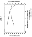
- Table 2 shows the results obtained with the average particle size of an alumina filler varied and the results obtained with a silica filler having a smaller particle size. These results are graphed in Fig. 5, in which the peel strength and the discharge capacity are plotted against the particle size of the alumina filler added. It can be seen that the peel strength somewhat decreases at a particle size of 1 ⁇ m or smaller, which was not problematical for practical use. It is also seen that, on the other hand, the discharge capacity tends to decrease as the average particle size becomes greater than 1 ⁇ m because of reduction of void volume in the adhesive resin layer.
- Example 1 Adhesive Peel Strength (gf/cm) Discharge Capacity (1C) (mAh) Resin Filler Weight Ratio Particle Size of Filler
- Example 1 PVDF alumina 1:1 0.01 50 60
- Example 3 PVDF alumina 1:1 0.1 60 55
- Example 4 PVDF alumina 1:1 1 65 50
- Example 5 PVDF silica 1:1 0.007 45 60 Compara.
- Example 3 PVDF alumina 1:1 10 60 25
- Table 3 shows the results obtained when the ratio of the alumina filler to the adhesive resin was varied. These results are graphed in Fig. 6, in which the peel strength and the battery capacity are plotted against volume percentage of the voids.
- the proportion of the adhesive resin in the void volume formed by the filler changes with a change of the filler to resin ratio, and a change of the void volume in the adhesive resin layer follows. If the volume percentage of the voids is 20% or less, passages for ions through the adhesive resin layer are diminished, resulting in an obvious reduction in discharge capacity. On the other hand, the adhesive strength tends to reduce with an increase of volume percentage of the voids. If the volume percentage of the voids is 80% or more, the amount of the filler is so large that the amount of the adhesive resin is insufficient, resulting in an extreme reduction in adhesive strength.
- Table 4 shows the results obtained when the thickness of the adhesive resin layer was varied.
- the peel strength and the discharge capacity are plotted against the thickness in Fig. 7.
- the adhesive resin layer does not cause hindrance to ion conduction while filling the gap formed by the unevenness of the electrodes so that a high discharge capacity can be secured.
- the thickness exceeds 50 ⁇ m, the passages for ions are so long that they become resistance and cause gradual reduction of discharge capacity.
- the thickness of the adhesive resin layer is increased to about 200 ⁇ m, the rate of reduction in discharge capacity is as high as about 50%.
- Example 5 PVDF alumina 1:10 0.01 10 90 20 65 Adhesive Thickness ( ⁇ m) Peel Strength (gf/cm) Discharge Capacity (1C) (mAh) Resin Filler Weight Ratio Particle Size of Filler
- Example 1 PVDF alumina 1:1 0.01 20 70 60
- Example 8 PVDF alumina 1:1 0.01 50 70 58
- Example 9 PVDF alumina 1:1 0.01 100 70 55
- Example 10 PVDF alumina 1:1 0.01 150 70 50
- Example 11 PVDF alumina 1:1 0.01 10 60 60 60
- Example 12 PVDF alumina 1:1 0.01 200 70 30
- Fig. 5 shows the results obtained from different kinds of fillers. It was proved that various fillers produce similar effects. In particular, great effects are obtained with inorganic compounds and polymers.
- Example 1 PVDF alumina 1:1 0.01 50 60
- Example 13 PVDF silica 1:1 0.01 50 60
- Example 14 PVDF silicon carbide 1:3 0.5 80 50
- Example 15 PVDF boron carbide 1:3 0.5 80 50
- Table 6 shows the results obtained when two kinds of fillers were used in combination. It is seen that similar effects are produced when fillers are used in various combinations. It is understood, in particular, that materials that contain no conducive materials show great effects.
- Table 7 shows the results obtained in case where the adhesive resin layer provided had a three layer structure having an insulating filler-containing adhesive resin layer (intermediate layer) between conductive filler-containing adhesive resin layers (electrode surface layers). It is understood that similar effects are obtained from various combinations of a conductive filler and an insulating filler.
- Table 8 shows the results of testing on battery characteristics of various battery structures. It proves that satisfactory battery characteristics can be obtained irrespective of the battery structure.
- Adhesive Battery Structure Discharge Capacity (1C) (mAh) Resin Filler Weight Ratio Particle Size of Filler Example 1 PVDF alumina 1:1 0.01 tabular unit electrode body 60
- Example 30 PVDF alumina 1:1 0.01 tabular laminated electrode body 360
- Example 31 PVDF alumina 1:1 0.01 " 360
- Example 32 PVDF alumina 1:1 0.01 tabular rolled electrode body 360
- Table 9 shows the results of testing on battery characteristics obtained when the method for applying the adhesive resin solution was altered. As shown in Table 9, satisfactory battery characteristics can be obtained irrespective of the application method as long as the coating thickness is substantially equal.
- Adhesive Method of Adhesive Application Discharge Capacity (1C) (mAh) Resin Filler Weight Ratio Particle Size of Filler Example 1 PVDF alumina 1:1 0.01 screen printing 60 Example 34 PVDF alumina 1:1 0.01 roll coater 60 Example 35 PVDF alumina 1:1 0.01 gravure printing 60 Example 36 PVDF alumina 1:1 0.01 doctor blade 60 Example 37 PVDF alumina 1;1 0.01 bar coater 60
- the battery according to the invention is used as a secondary battery, etc. in portable electronic equipment and has reduced size and weight as well as improved battery performance.
Abstract
Description
- This invention relates to a battery and, more particularly, to a battery structure that realizes a light, compact and thin battery having a high discharging capacity at a high current density and satisfactory cycle characteristics.
- Batteries have been used long as a main power source or a backup power source for a variety of equipment. The demand for batteries has recently been increasing with the development of portable electronic equipment, such as cellular phones and portable personal computers. Primary batteries and secondary batteries are available according to use. As to secondary batteries having great convenience, high performance batteries such as lithium ion secondary batteries and nickel-hydrogen batteries have been attracting attention. The present invention will hereinafter be explained by referring to lithium ion secondary batteries the demand of which has been steeply increasing for use in portable electronic equipment.
- Conventional lithium ion secondary batteries comprise a battery body that is a cylindrical roll of an electrode body or a stack of rectangular electrode bodies, the electrode body being composed of a positive electrode, a negative electrode, and a separator that is interposed between the two electrodes to serve for insulation and retention of an electrolyte. The battery body is put in a metal-made case so that the positive electrode, the negative electrode and the separator can be brought into intimate contact by the pressure of the case thereby to maintain the contact between each electrode and the separator.
- An electrical contact can be maintained by putting the battery body in a metal-made case, but there is a problem that the case, being made of metal, increases the weight of the battery. Moreover, it is difficult to make a thin metal case. Difficulty in making a thin case has been a great obstacle to fulfillment of the demand for batteries to be used in compact portable equipment.
- In this connection, U.S. Patent 5,437,692 discloses a structure in which a lithium ion-conducting polymer is used as an ion conducting layer, and a positive electrode and a negative electrode are joined to the ion-conducting layer with an adhesive layer containing a lithium compound. The inventors of the present invention previously proposed in Japanese Patent Application No. 8-338240 a battery structure requiring no metal-made rigid case and a process for producing the same, in which a positive electrode and a negative electrode are previously joined to a separator with an adhesive resin.
- The method comprising joining a positive and a negative electrode to a lithium ion-conducting polymer with an adhesive layer containing a lithium compound is disadvantageous in that the adhesive layer attains weak adhesion and becomes considerable resistance to ion conduction. The method comprising previously joining a positive and a negative electrode to a separator with an adhesive resin has made it feasible to maintain an electrical contact among them without imposing an external force but involves a problem that resistance between electrodes (i.e., a positive electrode and a negative electrode) increases because of the existence of not only the separator but the adhesive resin between the electrodes.
- Direct bonding of electrodes is a conceivable method. In this case, it is necessary to secure both ion conduction and electron insulation between electrodes that ought to be undertaken by a conventional ion-conducting polymer or separator, and yet to join the electrodes firmly.
- Further, the conventional ion-conducting polymer has weak adhesive strength, and the conventional adhesive resin joining electrodes and a separator has high adhesive strength but tends to deteriorate ion conductivity.
- Where the conventional adhesive resin is used, it turned out that cases are met with in which a solution of the adhesive resin is absorbed by a porous electrode only to exhibit low adhesive strength or even fail to bond.
- In addition, electrodes have their surfaces smoothed by pressing but still have unevenness of several microns to form vacancies where a separator and the electrodes are not in contact. The vacancies that should have been filled with an electrolyte may get starved of the electrolyte, which depends on the amount of the electrolyte supplied and the condition of use of the battery. Starvation of the electrolyte leads to an increase of internal resistivity of the battery and reductions in battery characteristics.
- The present invention has been reached, aiming at settlement of the above-described problems. It is an object of the invention to provide a light, compact and thin battery in which a positive and a negative electrode are joined firmly to maintain the adhesive strength while securing both electron insulation and ion conduction between electrodes and decreasing resistance between electrodes, i.e., internal resistance of a battery, to improve battery characteristics.
- A first battery according to the invention comprises a battery body having a positive and a negative electrode containing an active material, an electrolytic solution containing an electrolyte, and an adhesive resin layer which is interposed in between the positive electrode and the negative electrode and is joined to at least one of the positive and the negative electrodes, wherein the adhesive resin layer comprises at least one layer and contains fillers. In this structure, at least one of the positive electrode and the negative electrode is directly bonded to the adhesive resin layer, and the filler added makes the adhesive resin layer porous. The electrolyte and an adhesive resin solution can be held in the pores. As a result, internal resistivity of the battery can be reduced while maintaining adhesive strength to provide satisfactory battery characteristics.
- A second battery according to the invention is the above-described first battery, wherein the electrolyte is an organic electrolyte containing lithium ions. This mode, when applied to lithium ion secondary batteries which are required to have reduced weight and thickness, provides a high performance compact battery.
- A third battery according to the invention is the above-described first battery, wherein the average particle size of the filler is equal to or smaller than the particle size of the active material of the positive and negative electrodes. According to this mode, when the positive electrode and the negative electrode are joined with an adhesive resin, an adhesive resin solution having the adhesive resin dissolved in a solvent is hardly absorbed by the electrode active material so that it can be held as an adhesive resin layer to give necessary adhesive strength.
- A fourth battery according to the invention is the above-described first battery, wherein the average particle size of the filler is 1 µm or smaller. According to this embodiment, the filler manifests a proper thickening effect for the adhesive resin solution to make the adhesive resin solution hardly absorbable by the active material thereby securing necessary adhesive strength. Further, the filler makes the adhesive resin layer porous to improve ion conductivity thereby providing satisfactory battery characteristics.
- A fifth battery according to the invention is the above-described first battery, wherein the sum of a volume ratio of the adhesive resin and that of the filler per unit volume of the adhesive resin layer is less than 1. This mode secures the porosity of the formed adhesive resin layer thereby securing satisfactory ion conduction.
- A sixth battery according to the invention is the above-described first battery, wherein the sum of a volume ratio of the adhesive resin and that of the filler per unit volume of the adhesive resin layer is 0.2 to 0.8. According to this embodiment, the voids of the porous adhesive resin are filled with the electrolyte to exhibit sufficient ion conductivity.
- A seventh battery according to the invention is the above-described first battery, wherein the filler comprises at least one of non-conductive materials and semiconductors. According to this mode, the adhesive resin layer can be made porous to provide excellent battery characteristics including satisfactory ion conductivity while retaining adhesive strength.
- An eighth battery according to the invention is the above-described first battery, wherein the adhesive resin layer comprises a layer containing an electrically conductive filler and a layer containing at least one of non-conductive fillers and semiconductive fillers. According to this embodiment, internal resistivity of the battery can further be diminished by the conductive filler-containing layer.
- A ninth battery according to the invention is the above-described first battery, wherein the adhesive resin layer is constituted so as to fill the unevenness on the positive and the negative electrodes. This structure is effective in increasing the adhesive strength and preventing reduction of battery characteristics due to starvation of the electrolyte.
- A tenth battery according to the invention is the above-described first battery, wherein the battery body is a laminate of a plurality of electrode bodies each composed of a single layer of the positive electrode, a single layer of the adhesive resin layer, and a single layer of the negative electrode.
- An eleventh battery according to the invention is the above-described tenth battery, wherein the laminate is composed of the positive electrodes and the negative electrodes which are alternately interposed among a plurality of the adhesive resin layers.
- A twelfth battery according to the invention is the above-described tenth battery, wherein the laminate is composed of the positive electrode and the negative electrode which are alternately interposed between adhesive resin layers and rolled up.
- A thirteenth battery according to the invention is the above-described tenth battery, wherein the laminate is composed of the positive electrode and the negative electrode which are alternately interposed between adhesive resin layers and folded.
-
- Fig. 1 is a diagram showing the volume ratio in the adhesive resin layer of the battery according to the invention.
- Fig. 2 is a schematic cross-sectional view showing the space formed in the interface between a positive electrode and a negative electrode in the battery according to the invention.
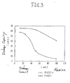
- Fig. 3 is a graph showing the change in discharge capacity brought about by addition of an alumina filler to a PVDF resin.
- Fig. 4 is a graph showing the change in discharge capacity caused by addition of an alumina filler to a PVA resin.
- Fig. 5 is a graph showing the relationship between peel strength and discharge capacity with an alumina filler added having a varied average particle size.
- Fig. 6 is a graph showing the relationship between peel strength and discharge capacity against volume percentage of the voids of an adhesive resin layer.
- Fig. 7 is a graph showing the relationship between peel strength and discharge capacity against thickness of an adhesive resin layer.
-
- The modes for carrying out the invention are hereinafter described by referring to the drawings.
- The present invention consists in joining a positive electrode and a negative electrode directly with an adhesive resin layer so as to reduce internal resistivity of the battery. The positive and the negative electrodes are made up of fine particles of the respective active materials bound by a binder and molded and are porous. Where an adhesive resin is used to join the positive and the negative electrodes, ion conductivity is lessened to deteriorate battery characteristics according as the amount of the adhesive resin is increased for strengthening the adhesion. This is because the adhesive resin layer is formed in a film to block the passages for ion migration. Therefore, the problem ought to be solved only if the adhesive resin is not filmy but porous. In the present invention the adhesive resin layer can be made porous by incorporating a filler into the adhesive resin.
- If an adhesive resin solution containing no filler is applied to an electrode (a positive and a negative electrode) for bonding, the adhesive resin solution will be absorbed by the electrode that is porous. Where a filler is mixed into the adhesive resin solution, the adhesive resin layer is provided with a porous structure formed by the filler. Since the adhesive resin solution is held in the pores of the porous structure and thereby prevented from being absorbed by the electrode, the adhesive resin solution can be maintained on the adherend surface. Further, this effect brings about an increase in viscosity of the adhesive resin solution to further improve adhesive resin holding properties.
- The average particle size of the filler to be added is preferably not greater than that of the electrode active material, particularly 1 µm or smaller. Filler particles having an average particle size of 1 µm or greater form pores the diameter of which approximates the pore size of the electrode, and the ability of holding the electrolytic solution decreases. Where filler particles have an average particle size equal to or greater than the particle size of the electrode active material, the pores lose the ability of holding the electrolyte, resulting in reductions of battery characteristics. That is, the filler added produces no substantial effect. The sedimentation velocity of the filler particles in the adhesive resin solution increases with an increasing average particle size, which considerably deteriorates the handling properties of the adhesive resin solution. With the average particle size being 1 µm or smaller, the filler moderately increases the viscosity of the adhesive resin solution and makes the adhesive resin layer porous. The adhesive resin solution and the electrolytic solution can thus be held in the interface between electrodes.
- The preference for the above-specified particle size of the filler applies to the particles constituting the most part of the filler. It does not matter if the filler contains particles out of that range.
- An adhesive resin solution using a solution type adhesive resin is made up of a filler, an adhesive resin, and a solvent. Since the solvent is removed on drying, the resulting adhesive resin layer is composed of the filler, the adhesive resin, and the voids formed on solvent's drying. The constitution of the adhesive resin layer is illustrated in Fig. 1. As can be seen from Fig. 1, the void volume formed by the filler is made up of the volume of the adhesive resin and the volume of the voids formed on solvent's drying. If all the void volume formed by the filler is filled with the adhesive resin, the adhesive resin layer fails to retain its porosity and becomes an insulating layer. Hence, the sum of a volume ratio of the adhesive resin and that of the filler per unit volume of the adhesive resin layer should be less than 1.
- In order for the adhesive resin layer to retain porosity, it is required as stated above that the sum of a volume ratio of the adhesive resin and that of the filler per unit volume of the adhesive resin layer be less than 1. On the other hand, in order for the voids of the porous adhesive resin to be filled with an electrolytic solution to exhibit sufficient ion conductivity, it is desirable for the adhesive resin layer to have a void volume of about 30%. From this standpoint, the sum of a volume ratio of the adhesive resin and that of the filler per unit volume of the adhesive resin layer should be 0.2 to 0.8. In other words the volume percentage of the voids based on the adhesive resin layer should be 20% to 80%.
- The filler is not particularly limited in material as far as the above-specified average particle size can be realized. Inorganic substances such as oxides, e.g., Al2O3, SiO2, ZrO2, and LiAlO2, carbides, e.g., SiC, B4C, and ZrC, and nitrides, e.g., SiN, BN, and TiN, are stable in an electrolyte and, because they have low conductivity, there is no fear of a short circuit even where the filler-containing adhesive resin is present to connect the electrodes. Because polymers such as polyolefin resins and polymethyl methacrylate have not only low conductivity but a small specific gravity, they are effective in minimizing an increase of weight as compared with inorganic fillers or metallic fillers.
- An inorganic salt, such as LiPF6 or LiClO4, that does not dissolve in an electrolytic solution or remains undissolved can serve as a filler to form fine pores. Even where the inorganic salt dissolves in an electrolytic solution, it leaves pores in the adhesive resin layer after dissolving, making it possible to increase the porosity of the adhesive resin layer.
- Where a conductive filler, such as carbon or metal, is used, the adhesive resin layer is endowed with electrical conductivity. The adhesive resin layer thus having conductivity, electron conduction is not hindered even if the adhesive resin enters the interstices of an electrode. However, in case such a conductive material as carbon is used, the adhesive resin layer loses the function of insulation, requiring some manipulation for prevention of a short circuit between the electrodes. A short circuit can be prevented by, for example, joining the electrodes via a three-layered adhesive resin layer composed of a pair of adhesive resin layers containing a conductive filler and an adhesive resin layer containing an insulating filler interposed therebetween. A short circuit can also be prevented by joining the electrodes via a two-layered adhesive resin layer composed of a layer containing a conductive filler and a layer containing an insulating filler.
- It is primarily required of the adhesive resin layer to have insulating properties against electron conduction between each electrode. In addition, where the filler-containing adhesive resin layer has such a form as to fill the space existing on the surface of each electrode due to the surface unevenness, the adhesive strength increases, and reduction in battery characteristics due to shortage of the electrolyte can be prevented. Because the surface of an electrode has not a little unevenness on the order of several microns, if is desirable that the filler-containing adhesive resin be present so as to fill the gap as shown in Fig. 2. Supposing an allowable reduction in discharge capacity due to resistance of the adhesive resin layer is up to 50%, a desirable thickness of the adhesive resin layer is 200 µm or smaller. In order to minimize the reduction in discharge capacity, a more desirable thickness of the adhesive resin layer is 50 µm or smaller.
- While the shape of the filler to be added to the adhesive resin is not particularly limited, it includes a spherical shape, an elliptical shape, a fibrous shape, and a flaky shape. A spherical filler will achieve an increased packing density, making the adhesive resin layer thinner. An elliptical, fibrous or flaky filler has an increased specific surface area to increase the void volume of the adhesive resin layer.
- While the adhesive resin is not particularly limited in kind, materials which, when present in battery materials, are not corroded by an electrolytic solution containing an electrolyte or an electrode-forming material and are capable of retaining adhesiveness are preferred. In particular, adhesive resins of solution type are more effective, for the adhesive resin layer can easily be made porous. In lithium ion secondary batteries containing an organic electrolyte, fluorocarbon resins represented by polyvinylidene fluoride (PVDF) and polymers containing polyvinyl alcohol in the molecular structure thereof, represented by polyvinyl alcohol, are preferred.
- While not limiting, the adhesive resin is preferably applied in a manner agreeable with a desired thickness and a coating form. Illustrative examples of coating methods include screen printing, bar coating, roll coating, gravure printing, and doctor blade coating.
- The invention does not impose particular restriction on the structure of batteries to which the invention is applied. The invention is applicable to batteries having a battery body comprising a positive electrode, a negative electrode, and an adhesive resin layer interposed between the electrodes. Accordingly, the battery body can be an electrode body composed of a single positive electrode layer, a single adhesive resin layer, and a single negative electrode layer (hereinafter referred to as a unit electrode body) or a laminated battery body comprising a plurality of such unit electrode bodies. When the invention is applied to a battery having such a laminated battery body, there is provided a battery having high performance and a high battery capacity.
- The laminated battery body can be formed by alternately superposing a plurality of positive electrodes and negative electrodes all cut in sizes via an adhesive resin layer or by rolling or folding one or more than one continuous sets of a positive electrode and a negative electrode to form a structure in which the positive electrode and the negative electrode alternate via an adhesive resin layer.
- The present invention is especially effective when applied to lithium secondary batteries, which is not limiting the application of the invention. The invention is also applicable to primary batteries, such as lithium primary batteries, manganese-zinc batteries, and silver-zinc batteries; and other types of secondary batteries, such as nickel-cadmium batteries, nickel-zinc batteries, nickel-hydrogen batteries, polymer batteries, and carbon secondary batteries.
- The details of the invention will now hereinafter be given by way of Examples, but the invention is by no means limited thereto.
- A positive electrode active material layer consisting of 91 parts by weight of LiCoO2 having an average particle size of 10 µm (produced by Nippon Chemical Industrial Co., Ltd.), 6 parts by weight of graphite powder (produced by LONZA Ltd.), and 3 parts by weight of polyvinylidene fluoride (produced by Kureha Chemical Industry Co., Ltd.) was applied to an aluminum foil substrate to an average coating thickness of 80 µm to form a positive electrode. A negative electrode active material layer consisting of 90 parts by weight of mesophase microbeads (produced by Osaka Gas Co., Ltd.) having an average particle size of 8 µm and 10 parts by weight of polyvinylidene fluoride was applied to a copper substrate to an average coating thickness of 80 µm to form a negative electrode. An adhesive resin solution for joining these electrodes was prepared by dispersing and dissolving polyvinylidene fluoride (produced by Elf Atochem Japan) and alumina powder having an average particle size of 0.01 µm (produced by Degussa Corporation) in a concentration of 10 wt% each in N-methlpyrrolidone. The positive electrode and the negative electrode were cut in sizes of 50 mm x 50 mm and 55 mm x 55 mm, respectively. A cut piece of the negative electrode was coated with the adhesive resin solution on a screen printing machine using a 200 mesh screen and bonded to a cut piece of the positive electrode. The laminate was dried in a drier at 80°C for 1 hour to prepare a unit electrode body. The thickness of the formed adhesive resin layer was controllable by choice of the mesh size. In this example, the thickness was 20 µm.
- The adhesive strength between the negative electrode and the positive electrode of the resulting electrode body was measured by a peel test at 90°.
- The resulting electrode body, with a current collecting tab spot-welded to the positive and the negative electrode thereof, was put in a bag made of an aluminum laminate sheet. An electrolytic solution was poured into the bag, and the opening of the bag was sealed to complete a battery. The battery was charged and discharged at 1C, and a discharge capacity was measured as an indication of battery characteristics.
- Electrodes were prepared, a battery was assembled, and evaluation was made in the same manner as in Example 1, except for using an adhesive resin solution prepared by dissolving polyvinylidene fluoride (PVDF) in N-methylpyrrolidone (NMP) in a concentration of 10 wt%.
- Electrodes were prepared, a battery was assembled, and evaluation was made in the same manner as in Example 1, except for using an adhesive resin solution prepared by dissolving 2 wt% of polyvinyl alcohol and 5 wt% of alumina powder having an average particle size of 0.01 µm in N-methylpyrrolidone.
- Electrodes were prepared, a battery was assembled, and evaluation was made in the same manner as in Example 2, except for using an adhesive resin solution prepared by dissolving 2 wt% of polyvinyl alcohol in N-methylpyrrolidone.
- Electrodes were prepared, a battery was assembled, and evaluation was made in the same manner as in Example 1, except for using an adhesive resin solution prepared by dissolving and dispersing 10 wt% of polyvinylidene fluoride and 10 wt% of alumina powder having an average particle size of 0.1 µm in N-methylpyrrolidone.
- Electrodes were prepared, a battery was assembled, and evaluation was made in the same manner as in Example 1, except for using an adhesive resin solution prepared by dissolving and dispersing 10 wt% of polyvinylidene fluoride and 10 wt% of alumina powder having an average particle size of 1 µm in N-methylpyrrolidone.
- Electrodes were prepared, a battery was assembled, and evaluation was made in the same manner as in Example 1, except for using an adhesive resin solution prepared by dissolving and dispersing 10 wt% of polyvinylidene fluoride and 10 wt% of silica powder having an average particle size of 0.007 µm in N-methylpyrrolidone.
- Electrodes were prepared, a battery was assembled, and evaluation was made in the same manner as in Example 1, except for using an adhesive resin solution prepared by dissolving and dispersing 10 wt% of polyvinylidene fluoride and 10 wt% of alumina powder having an average particle size of 10 µm in N-methylpyrrolidone.
- Electrodes were prepared, a battery was assembled, and evaluation was made in the same manner as in Example 1, except for using an adhesive resin solution prepared by dissolving and dispersing 10 wt% of polyvinylidene fluoride and 5 wt% of alumina powder having an average particle size of 0.01 µm in N-methylpyrrolidone.
- Electrodes were prepared, a battery was assembled, and evaluation was made in the same manner as in Example 1, except for using an adhesive resin solution prepared by dissolving and dispersing 5 wt% of polyvinylidene fluoride and 25 wt% of alumina powder having an average particle size of 0.01 µm in N-methylpyrrolidone.
- Electrodes were prepared, a battery was assembled, and evaluation was made in the same manner as in Example 1, except for using an adhesive resin solution prepared by dissolving and dispersing 10 wt% of polyvinylidene fluoride and 1 wt% of alumina powder having an average particle size of 0.01 µm in N-methylpyrrolidone.
- Electrodes were prepared, a battery was assembled, and evaluation was made in the same manner as in Example 1, except for using an adhesive resin solution prepared by dissolving and dispersing 3 wt% of polyvinylidene fluoride and 30 wt% of alumina powder having an average particle size of 0.01 µm in N-methylpyrrolidone.
- Electrodes were prepared, a battery was assembled, and evaluation was made in the same manner as in Example 1, except for using an adhesive resin solution prepared by dissolving and dispersing 10 wt% of polyvinylidene fluoride and 10 wt% of alumina powder having an average particle size of 0.01 µm in N-methylpyrrolidone and using a 150 mesh screen for applying the adhesive resin solution (the thickness of the resulting adhesive resin layer was 50 µm).
- Electrodes were prepared, a battery was assembled, and evaluation was made in the same manner as in Example 1, except for using an adhesive resin solution prepared by dissolving and dispersing 10 wt% of polyvinylidene fluoride and 10 wt% of alumina powder having an average particle size of 0.01 µm in N-methylpyrrolidone and using a 100 mesh screen for applying the adhesive resin solution (the thickness of the resulting adhesive resin layer was 100 µm).
- Electrodes were prepared, a battery was assembled, and evaluation was made in the same manner as in Example 1, except for using an adhesive resin solution prepared by dissolving and dispersing 10 wt% of polyvinylidene fluoride and 10 wt% of alumina powder having an average particle size of 0.01 µm in N-methylpyrrolidone and using a 60 mesh screen for applying the adhesive resin solution (the thickness of the resulting adhesive resin layer was 150 µm).
- Electrodes were prepared, a battery was assembled, and evaluation was made in the same manner as in Example 1, except for using an adhesive resin solution prepared by dissolving and dispersing 10 wt% of polyvinylidene fluoride and 10 wt% of alumina powder having an average particle size of 0.01 µm in N-methylpyrrolidone and using a 250 mesh screen for applying the adhesive resin solution (the thickness of the resulting adhesive resin layer was 10 µm).
- Electrodes were prepared, a battery was assembled, and evaluation was made in the same manner as in Example 1, except for using an adhesive resin solution prepared by dissolving and dispersing 10 wt% of polyvinylidene fluoride and 10 wt% of alumina powder having an average particle size of 0.01 µm in N-Methylpyrrolidone and using a 50 mesh screen for applying the adhesive resin solution (the thickness of the resulting adhesive resin layer was 200 µm).
- Electrodes were prepared, a battery was assembled, and evaluation was made in the same manner as in Example 1, except for using an adhesive resin solution prepared by dissolving and dispersing 10 wt% of polyvinylidene fluoride and 10 wt% of silica powder having an average particle size of 0.01 µm (produced by Aerosil Co., Ltd.) in N-methylpyrrolidone.
- Electrodes were prepared, a battery was assembled, and evaluation was made in the same manner as in Example 1, except for using an adhesive resin solution prepared by dissolving and dispersing 10 wt% of polyvinylidene fluoride and 30 wt% of silicon carbide powder having an average particle size of 0.5 µm (produced by Seimi Chemical Co., Ltd.) in N-methylpyrrolidone and using a 100 mesh screen in applying the adhesive resin solution.
- Electrodes were prepared, a battery was assembled, and evaluation was made in the same manner as in Example 1, except for using an adhesive resin solution prepared by dissolving and dispersing 10 wt% of polyvinylidene fluoride and 30 wt% of boron carbide powder having an average particle size of 0.5 µm (produced by Seimi Chemical Co., Ltd.) in N-methylpyrrolidone.
- Electrodes were prepared, a battery was assembled, and evaluation was made in the same manner as in Example 1, except for using an adhesive resin solution prepared by dissolving and dispersing 10 wt% of polyvinylidene fluoride and 30 wt% of silicon nitride powder having an average particle size of 0.5 µm (produced by Seimi Chemical Co., Ltd.) in N-methylpyrrolidone.
- Electrodes were prepared, a battery was assembled, and evaluation was made in the same manner as in Example 1, except for using an adhesive resin solution prepared by dissolving and dispersing 10 wt% of polyvinylidene fluoride and 5 wt% of polymethyl methacrylate (PMMA) powder having an average particle size of 0.5 µm in N-methylpyrrolidone.
- Electrodes were prepared, a battery was assembled, and evaluation was made in the same manner as in Example 1, except for using an adhesive resin solution prepared by dissolving and dispersing 10 wt% of polyvinylidene fluoride, 9 wt% of alumina powder having an average particle size of 0.01 µm, and 1 wt% of alumina powder having an average particle size of 1 µm in N-methylpyrrolidone.
- Electrodes were prepared, a battery was assembled, and evaluation was made in the same manner as in Example 1, except for using an adhesive resin solution prepared by dissolving and dispersing 10 wt% of polyvinylidene fluoride, 5 wt% of alumina powder having an average particle size of 0.01 µm, and 5 wt% of silica powder having an average particle size of 0.01 µm in N-methylpyrrolidone.
- Electrodes were prepared, a battery was assembled, and evaluation was made in the same manner as in Example 1, except for using an adhesive resin solution prepared by dissolving and dispersing 10 wt% of polyvinylidene fluoride, 9 wt% of alumina powder having an average particle size of 0.01 µm, and 9 wt% of silica powder having an average particle size of 0.5 µm in N-methylpyrrolidone.
- Electrodes were prepared, a battery was assembled, and evaluation was made in the same manner as in Example 1, except for using an adhesive resin solution prepared by dissolving and dispersing 10 wt% of polyvinylidene fluoride, 9 wt% of alumina powder having an average particle size of 0.01 µm, and 1 wt% of polymethyl methacrylate powder having an average particle size of 0.5 µm in N-methylpyrrolidone.
- Electrodes were prepared, a battery was assembled, and evaluation was made in the same manner as in Example 1, except for using an adhesive resin solution prepared by dissolving and dispersing 10 wt% of polyvinylidene fluoride, 9 wt% of alumina powder having an average particle size of 0.01 µm, and 1 wt% of alumina powder having an average particle size of 0.5 µm in N-methylpyrrolidone.
- Electrodes were prepared, a battery was assembled, and evaluation was made in the same manner as in Example 1, except for using an adhesive resin solution prepared by dissolving and dispersing 10 wt% of polyvinylidene fluoride, 5 wt% of silicon carbide powder having an average particle size of 0.5 µm, and 5 wt% of polymethyl methacrylate powder having an average particle size of 0.5 µm in N-methylpyrrolidone.
- Electrodes were prepared, a battery was assembled, and evaluation was made in the same manner as in Example 1 except for the following. An adhesive resin solution prepared by dissolving and dispersing 10 wt% of polyvinylidene fluoride and 20 wt% of iron powder having an average particle size of 0.5 µm in N-methylpyrrolidone was applied to a side of each electrode on a screen printing machine using a 400 mesh screen and dried. An adhesive resin solution prepared by dissolving and dispersing 10 wt% of polyvinylidene fluoride and 10 wt% of alumina powder having an average particle size of 0.01 µm in N-methylpyrrolidone was applied to the previously coated side of the negative electrode on a screen printing machine using a 200 mesh screen. The previously coated side of the positive electrode was stuck thereto, and the laminate was dried.
- Electrodes were prepared, a battery was assembled, and evaluation was made in the same manner as in Example 1 except for the following. An adhesive resin solution prepared by dissolving and dispersing 10 wt% of polyvinylidene fluoride and 50 wt% of carbon powder having an average particle size of 1 µm (produced by Osaka Gas Co., Ltd.) in N-methylpyrrolidone was applied to a side of each electrode on a screen printing machine using a 400 mesh screen and dried. An adhesive resin solution prepared by dissolving and dispersing 10 wt% of polyvinylidene fluoride and 10 wt% of alumina powder having an average particle size of 0.01 µm in N-methylpyrrolidone was applied to the previously coated side of the negative electrode on a screen printing machine using a 200 mesh screen, and the previously coated side of the positive electrode was stuck thereto, followed by drying.
- Electrodes were prepared, a battery was assembled, and evaluation was made in the same manner as in Example 1 except for the following. An adhesive resin solution prepared by dissolving and dispersing 10 wt% of polyvinylidene fluoride and 20 wt% of iron powder having an average particle size of 1 µm in N-methylpyrrolidone was applied to a side of each electrode on a screen printing machine using a 400 mesh screen and dried. An adhesive resin solution prepared by dissolving and dispersing 10 wt% of polyvinylidene fluoride and 30 wt% of silicon carbide powder having an average particle size of 0.5 µm in N-methylpyrrolidone was applied to the previously coated side of the negative electrode on a screen printing machine using a 200 mesh screen. The previously coated side of the positive electrode was stuck thereto, and the resulting laminate was dried. Electrodes were prepared, a battery was assembled, and evaluation was made in the same manner as in Example 1 except for using an adhesive resin solution prepared by dissolving and dispersing 10 wt% of polyvinylidene fluoride, 9 wt% of alumina powder having an average particle size of 0.01 µm, and 1 wt% of iron powder having an average particle size of 0.5 µm in N-methylpyrrolidone.
- Electrodes were prepared, a battery was assembled, and evaluation was made in the same manner as in Example 1 except for the following. An adhesive resin solution prepared by dissolving and dispersing 10 wt% of polyvinylidene fluoride and 50 wt% of carbon powder having an average particle size of 1 µm in N-methylpyrrolidone was applied to a side of each electrode on a screen printing machine using a 400 mesh screen and dried. An adhesive resin solution prepared by dissolving and dispersing 10 wt% of polyvinylidene fluoride and 30 wt% of silicon carbide powder having an average particle size of 0.5 µm in N-methylpyrrolidone was applied to the previously coated side of the negative electrode on a screen printing machine using a 200 mesh screen. The previously coated side of the positive electrode was stuck thereto, and the resulting laminate was dried.
- Electrodes were prepared, a battery was assembled, and evaluation was made in the same manner as in Example 1 except for the following. An adhesive resin solution prepared by dissolving and dispersing 10 wt% of polyvinylidene fluoride and 20 wt% of iron powder having an average particle size of 1 µm in N-methylpyrrolidone was applied to a side of each electrode on a screen printing machine using a 400 mesh screen and dried. An adhesive resin solution prepared by dissolving and dispersing 10 wt% of polyvinylidene fluoride and 5 wt% of polymethyl methacrylate powder having an average particle size of 0.5 µm in N-methylpyrrolidone was applied to the previously coated side of the negative electrode on a screen printing machine using a 200 mesh screen. The previously coated side of the positive electrode was stuck thereto, and the resulting laminate was dried.
- Electrodes were prepared, a battery was assembled, and evaluation was made in the same manner as in Example 1 except for the following. An adhesive resin solution prepared by dissolving and dispersing 10 wt% of polyvinylidene fluoride and 50 wt% of carbon powder having an average particle size of 1 µm in N-methylpyrrolidone was applied to a side of each electrode on a screen printing machine using a 400 mesh screen and dried. An adhesive resin solution prepared by dissolving and dispersing 10 wt% of polyvinylidene fluoride and 5 wt% of polymethyl methacrylate powder having an average particle size of 0.5 µm in N-methylpyrrolidone was applied to the previously coated side of the negative electrode on a screen printing machine using a 200 mesh screen. The previously coated side of the positive electrode was stuck thereto, and the resulting laminate was dried.
- A positive electrode, a negative electrode, and an adhesive resin solution were prepared in the same manner as in Example 1. The positive electrode and the negative electrode were cut in pieces of 50 mm x 50 mm and 55 mm x 55 mm, respectively. The adhesive resin solution was applied to a side of a cut piece of the negative electrode on a screen printing machine, and a cut piece of the positive electrode was stuck thereto. Then, a side of another piece of the negative electrode was coated with the adhesive resin solution and bonded to the previously bonded positive electrode. These steps were repeated 6 times to build up a laminated battery body. The battery body was dried while applying pressure to obtain a tabular laminated battery body having positive and negative electrodes alternately bonded via an adhesive resin layer. The battery characteristics of the resulting battery body were evaluated in the same manner as in Example 1.
- A positive electrode, a negative electrode, and an adhesive resin solution were prepared in the same manner as in Example 1. The positive electrode and the negative electrode were cut in pieces of 50 mm x 50 mm and 55 mm x 55 mm, respectively. The adhesive resin solution was applied to a side of a cut piece of the positive electrode on a screen printing machine, and a cut piece of the negative electrode was stuck thereto. Then, a side of another piece of the positive electrode was coated with the adhesive resin solution and bonded to the previously bonded negative electrode. These steps were repeated 6 times to build up a laminated battery body. The battery body was dried while applying pressure to obtain a tabular laminated battery body having positive and negative electrodes alternately bonded with an adhesive resin layer. The battery characteristics of the resulting battery body were evaluated in the same manner as in Example 1.
- A positive electrode, a negative electrode, and an adhesive resin solution were prepared in the same manner as in Example 1. A band of 300 mm x 50 mm and of 305 mm x 55 mm was cut out of the positive electrode and the negative electrode, respectively. The adhesive resin solution was applied to a side of the negative electrode band on a screen printing machine. One end of the coated negative electrode was folded back at a prescribed length. The positive electrode band was inserted into the center of the fold, and the folded end was sent to a laminator. Subsequently, the positive electrode and the negative electrode were superposed and passed through the laminator. The laminate was rolled up into an oblong cylinder while applying the adhesive resin solution to the other side of the negative electrode that was opposite to the side previously coated with the adhesive resin solution.
- The rolled oblong battery body was dried while applying pressure to obtain a tabular roll type battery body having positive and negative electrodes bonded alternately via an adhesive resin layer. The battery characteristics of the resulting battery body were evaluated in the same manner as in Example 1.
- A positive electrode, a negative electrode, and an adhesive resin solution were prepared in the same manner as in Example 1. A band of 300 mm x 50 mm and of 305 mm x 55 mm was cut out of the positive electrode and the negative electrode, respectively. The adhesive resin solution was applied to a side of the separator on a screen printing machine. One end of the coated positive electrode was folded back at a prescribed length. The negative electrode band was inserted into the center of the fold. Subsequently, the folded positive electrode and the negative electrode were superposed and passed through the laminator. The adhesive resin solution was applied to the other side of the positive electrode that was opposite to the side previously coated with the adhesive resin solution, and the laminate was rolled up into an oblong cylinder.
- The rolled oblong battery body was dried while applying pressure to obtain a tabular roll type battery body having positive and negative electrodes bonded alternately via an adhesive resin layer. The battery characteristics of the resulting battery body were evaluated in the same manner as in Example 1.
- A positive electrode, a negative electrode, and an adhesive resin solution were prepared in the same manner as in Example 1. A piece of 50 mm x 50 mm and of 55 mm x 55 mm was cut out of the positive electrode and the negative electrode, respectively. The adhesive resin solution was applied to a side of the negative electrode by means of a roll coater the nip of which was adjusted to give a coating thickness substantially equal to that in Example 1. The negative electrode and the positive electrode were joined and dried in a drier at 80°C for 1 hour to obtain a battery body comprising a unit electrode body having the positive electrode and the negative electrode bonded together. The battery characteristics of the resulting battery body were evaluated in the same manner as in Example 1.
- A positive electrode, a negative electrode, and an adhesive resin solution were prepared in the same manner as in Example 1. A piece of 50 mm x 50 mm and of 55 mm x 55 mm was cut out of the positive electrode and the negative electrode, respectively. The adhesive resin solution was applied to a side of the negative electrode by means of a gravure printing machine the nip of which was adjusted to give a coating thickness substantially equal to that in Example 1. The negative electrode and the positive electrode were joined and dried in a drier at 80°C for 1 hour to obtain a battery body comprising a unit electrode body having the positive electrode and the negative electrode bonded together. The battery characteristics of the resulting battery body were evaluated in the same manner as in Example 1.
- A positive electrode, a negative electrode, and an adhesive resin solution were prepared in the same manner as in Example 1. A piece of 50 mm x 50 mm and of 55 mm x 55 mm was cut out of the positive electrode and the negative electrode, respectively. The adhesive resin solution was applied to a side of the negative electrode by means of a doctor blade coater the gap of which was adjusted to give a coating thickness substantially equal to that in Example 1. The negative electrode and the positive electrode were joined and dried in a drier at 80°C for 1 hour to obtain a battery body comprising a unit electrode body having the positive electrode and the negative electrode bonded together. The battery characteristics of the resulting battery body were evaluated in the same manner as in Example 1.
- A positive electrode, a negative electrode, and an adhesive resin solution were prepared in the same manner as in Example 1. A piece of 50 mm x 50 mm and of 55 mm x 55 mm was cut out of the positive electrode and the negative electrode, respectively. The adhesive resin solution was applied to a side of the negative electrode by means of a bar coater the gap of which was adjusted to give a coating thickness substantially equal to that in Example 1. The negative electrode and the positive electrode were joined and dried in a drier at 80°C for 1 hour to obtain a battery body comprising a unit electrode body having the positive electrode and the negative electrode bonded together. The battery characteristics of the resulting battery body were evaluated in the same manner as in Example 1.
- The adhesive strength of the prepared electrodes and the discharge capacity in charging and discharging the prepared batteries at 1C are shown in Tables 1 through 9. The graphs of discharge capacity vs. charging and discharging current with different adhesive resins are shown in Figs. 3 and 4. Comparisons between Example 1 and Comparative Example 1 and between Example 2 and Comparative Example 2 reveal that addition of a filler to an adhesive resin solution brings about improvement in discharge capacity, especially under a high load.
Adhesive Peel Strength (gf/cm) Discharge Capacity (1C) (mAh) Resin Filler Weight Ratio Particle Size of Filler Example 1 PVDF alumina 1:1 0.01 50 60 Compara. Example 1 PVDF none - - 100 20 Example 2 PVA alumina 2:5 0.01 70 60 Compara. Example 2 PVA none - - 100 30 - Table 2 shows the results obtained with the average particle size of an alumina filler varied and the results obtained with a silica filler having a smaller particle size. These results are graphed in Fig. 5, in which the peel strength and the discharge capacity are plotted against the particle size of the alumina filler added. It can be seen that the peel strength somewhat decreases at a particle size of 1 µm or smaller, which was not problematical for practical use. It is also seen that, on the other hand, the discharge capacity tends to decrease as the average particle size becomes greater than 1 µm because of reduction of void volume in the adhesive resin layer.
Adhesive Peel Strength (gf/cm) Discharge Capacity (1C) (mAh) Resin Filler Weight Ratio Particle Size of Filler Example 1 PVDF alumina 1:1 0.01 50 60 Example 3 PVDF alumina 1:1 0.1 60 55 Example 4 PVDF alumina 1:1 1 65 50 Example 5 PVDF silica 1:1 0.007 45 60 Compara. Example 3 PVDF alumina 1:1 10 60 25 - Table 3 shows the results obtained when the ratio of the alumina filler to the adhesive resin was varied. These results are graphed in Fig. 6, in which the peel strength and the battery capacity are plotted against volume percentage of the voids. The proportion of the adhesive resin in the void volume formed by the filler changes with a change of the filler to resin ratio, and a change of the void volume in the adhesive resin layer follows. If the volume percentage of the voids is 20% or less, passages for ions through the adhesive resin layer are diminished, resulting in an obvious reduction in discharge capacity. On the other hand, the adhesive strength tends to reduce with an increase of volume percentage of the voids. If the volume percentage of the voids is 80% or more, the amount of the filler is so large that the amount of the adhesive resin is insufficient, resulting in an extreme reduction in adhesive strength.
- Table 4 shows the results obtained when the thickness of the adhesive resin layer was varied. The peel strength and the discharge capacity are plotted against the thickness in Fig. 7. As can be seen, with a coating thickness of 50 µm or smaller, the adhesive resin layer does not cause hindrance to ion conduction while filling the gap formed by the unevenness of the electrodes so that a high discharge capacity can be secured. If the thickness exceeds 50 µm, the passages for ions are so long that they become resistance and cause gradual reduction of discharge capacity. If the thickness of the adhesive resin layer is increased to about 200 µm, the rate of reduction in discharge capacity is as high as about 50%.
Adhesive Volume of Solid Matter (%) Void Volume (%) Peel Strength (gf/cm) Discharge Capacity (1C) (mAh) Resin Filler Weight Ratio Particle Size of Filler Example 1 PVDF alumina 1:1 0.01 50 50 70 62 Example 6 PVDF alumina 2:1 0.01 70 30 85 58 Example 7 PVDF alumina 1:5 0.01 30 70 60 65 Compara. Example 4 PVDF alumina 10:1 0.01 90 10 100 20 Compara. Example 5 PVDF alumina 1:10 0.01 10 90 20 65 Adhesive Thickness (µm) Peel Strength (gf/cm) Discharge Capacity (1C) (mAh) Resin Filler Weight Ratio Particle Size of Filler Example 1 PVDF alumina 1:1 0.01 20 70 60 Example 8 PVDF alumina 1:1 0.01 50 70 58 Example 9 PVDF alumina 1:1 0.01 100 70 55 Example 10 PVDF alumina 1:1 0.01 150 70 50 Example 11 PVDF alumina 1:1 0.01 10 60 60 Example 12 PVDF alumina 1:1 0.01 200 70 30 - Fig. 5 shows the results obtained from different kinds of fillers. It was proved that various fillers produce similar effects. In particular, great effects are obtained with inorganic compounds and polymers.
Adhesive Peel Strength (gf/cm) Discharge Capacity (1C) (mAh) Resin Filler Weight Ratio Particle Size of Filler Example 1 PVDF alumina 1:1 0.01 50 60 Example 13 PVDF silica 1:1 0.01 50 60 Example 14 PVDF silicon carbide 1:3 0.5 80 50 Example 15 PVDF boron carbide 1:3 0.5 80 50 Example 16 PVDF silicon nitride 1:3 0.5 80 50 Example 17 PVDF PMMA 2:1 0.5 80 50 - Table 6 shows the results obtained when two kinds of fillers were used in combination. It is seen that similar effects are produced when fillers are used in various combinations. It is understood, in particular, that materials that contain no conducive materials show great effects.

- Table 7 shows the results obtained in case where the adhesive resin layer provided had a three layer structure having an insulating filler-containing adhesive resin layer (intermediate layer) between conductive filler-containing adhesive resin layers (electrode surface layers). It is understood that similar effects are obtained from various combinations of a conductive filler and an insulating filler.

- Table 8 shows the results of testing on battery characteristics of various battery structures. It proves that satisfactory battery characteristics can be obtained irrespective of the battery structure.
Adhesive Battery Structure Discharge Capacity (1C) (mAh) Resin Filler Weight Ratio Particle Size of Filler Example 1 PVDF alumina 1:1 0.01 tabular unit electrode body 60 Example 30 PVDF alumina 1:1 0.01 tabular laminated electrode body 360 Example 31 PVDF alumina 1:1 0.01 " 360 Example 32 PVDF alumina 1:1 0.01 tabular rolled electrode body 360 Example 33 PVDF alumina 1;1 0.01 " 360 - Table 9 shows the results of testing on battery characteristics obtained when the method for applying the adhesive resin solution was altered. As shown in Table 9, satisfactory battery characteristics can be obtained irrespective of the application method as long as the coating thickness is substantially equal.
Adhesive Method of Adhesive Application Discharge Capacity (1C) (mAh) Resin Filler Weight Ratio Particle Size of Filler Example 1 PVDF alumina 1:1 0.01 screen printing 60 Example 34 PVDF alumina 1:1 0.01 roll coater 60 Example 35 PVDF alumina 1:1 0.01 gravure printing 60 Example 36 PVDF alumina 1:1 0.01 doctor blade 60 Example 37 PVDF alumina 1;1 0.01 bar coater 60 - The battery according to the invention is used as a secondary battery, etc. in portable electronic equipment and has reduced size and weight as well as improved battery performance.
Claims (13)
- A battery comprising a battery body including:a positive and a negative electrode containing an active material,an electrolytic solution containing an electrolyte, andan adhesive resin layer which is interposed in between the positive electrode and the negative electrode and is joined to at least one of the positive and the negative electrodes,wherein the adhesive resin layer comprises at least one layer and contains fillers.
- A battery according to claim 1, wherein said electrolyte is an organic electrolyte containing lithium ions.
- A battery according to claim 1, wherein the average particle size of said filler is equal to or smaller than the particle size of the active material constituting each electrode.
- A battery according to claim 1, wherein said average particle size of said filler is 1 µm or smaller.
- A battery according to claim 1, wherein the sum of a volume ratio of the adhesive resin and that of the filler per unit volume of said adhesive resin layer is less than 1.
- A battery according to claim 1, wherein the sum of a volume ratio of the adhesive resin and that of the filler per unit volume of said adhesive resin layer is 0.2 to 0.8.
- A battery according to claim 1, wherein said filler comprises at least one of non-conductive materials and semiconductors.
- A battery according to claim 1, wherein said adhesive resin layer comprises a layer containing an electrically conductive filler and a layer containing at least one of non-conductive fillers and semiconductive fillers.
- A battery according to claim 1, wherein said adhesive resin layer is constituted so as to fill the unevenness of the positive electrode and the negative electrode.
- A battery according to claim 1, wherein said battery body is a laminate of a plurality of electrode bodies each composed of a single layer of the positive electrode, a single layer of the adhesive resin layer, and a single layer of the negative electrode.
- A battery according to claim 10, wherein said laminate is composed of the positive electrodes and the negative electrodes interposed alternately among a plurality of the adhesive resin layers.
- A battery according to claim 10, wherein said laminate is composed of the positive electrode and the negative electrode which are alternately interposed between adhesive resin layers and rolled up.
- A battery according to claim 10, wherein said laminate is composed of the positive electrode and the negative electrode which are alternately interposed between adhesive resin layers and folded.
Applications Claiming Priority (1)
| Application Number | Priority Date | Filing Date | Title |
|---|---|---|---|
| PCT/JP1998/000248 WO1999038224A1 (en) | 1998-01-22 | 1998-01-22 | Battery |
Publications (3)
| Publication Number | Publication Date |
|---|---|
| EP0969542A1 true EP0969542A1 (en) | 2000-01-05 |
| EP0969542A4 EP0969542A4 (en) | 2005-03-16 |
| EP0969542B1 EP0969542B1 (en) | 2010-06-23 |
Family
ID=14207450
Family Applications (1)
| Application Number | Title | Priority Date | Filing Date |
|---|---|---|---|
| EP98900705A Expired - Lifetime EP0969542B1 (en) | 1998-01-22 | 1998-01-22 | Battery |
Country Status (6)
| Country | Link |
|---|---|
| EP (1) | EP0969542B1 (en) |
| JP (1) | JP4077045B2 (en) |
| KR (1) | KR100329295B1 (en) |
| CN (1) | CN1127166C (en) |
| DE (1) | DE69841740D1 (en) |
| WO (1) | WO1999038224A1 (en) |
Cited By (1)
| Publication number | Priority date | Publication date | Assignee | Title |
|---|---|---|---|---|
| US9647471B2 (en) | 2014-10-17 | 2017-05-09 | Trion Energy Solutions Corp. | Battery management system and method |
Families Citing this family (7)
| Publication number | Priority date | Publication date | Assignee | Title |
|---|---|---|---|---|
| KR100666821B1 (en) * | 2004-02-07 | 2007-01-09 | 주식회사 엘지화학 | Organic/inorganic composite porous layer-coated electrode and electrochemical device comprising the same |
| JP4649862B2 (en) * | 2004-04-02 | 2011-03-16 | パナソニック株式会社 | Lithium ion secondary battery and manufacturing method thereof |
| JP5426551B2 (en) | 2007-08-21 | 2014-02-26 | エー123 システムズ, インコーポレイテッド | Electrochemical cell separator and method for producing the same |
| KR20150137541A (en) * | 2014-05-30 | 2015-12-09 | 에스케이이노베이션 주식회사 | Li Secondary Battery |
| US9646774B2 (en) | 2014-06-05 | 2017-05-09 | Trion Energy Solutions Corp. | Power wafer |
| JP7341957B2 (en) * | 2020-07-28 | 2023-09-11 | 帝人株式会社 | Non-aqueous secondary battery |
| EP4190860A4 (en) | 2020-07-28 | 2024-04-10 | Teijin Ltd | Nonaqueous secondary battery |
Citations (2)
| Publication number | Priority date | Publication date | Assignee | Title |
|---|---|---|---|---|
| US5512389A (en) * | 1994-11-02 | 1996-04-30 | Dasgupta; Sankar | Rechargeable non-aqueous thin film lithium battery |
| JPH09312152A (en) * | 1996-05-22 | 1997-12-02 | Toyota Motor Corp | Structure of separator for battery |
Family Cites Families (4)
| Publication number | Priority date | Publication date | Assignee | Title |
|---|---|---|---|---|
| US5180674A (en) * | 1990-04-16 | 1993-01-19 | The Trustees Of The University Of Pennsylvania | Saccharide compositions, methods and apparatus for their synthesis |
| JP3065797B2 (en) * | 1992-07-29 | 2000-07-17 | 新神戸電機株式会社 | Lithium secondary battery |
| US5460904A (en) * | 1993-08-23 | 1995-10-24 | Bell Communications Research, Inc. | Electrolyte activatable lithium-ion rechargeable battery cell |
| US5665265A (en) * | 1996-09-23 | 1997-09-09 | Motorola, Inc., | Non woven gel electrolyte for electrochemical cells |
-
1998
- 1998-01-22 DE DE69841740T patent/DE69841740D1/en not_active Expired - Lifetime
- 1998-01-22 WO PCT/JP1998/000248 patent/WO1999038224A1/en active IP Right Grant
- 1998-01-22 EP EP98900705A patent/EP0969542B1/en not_active Expired - Lifetime
- 1998-01-22 JP JP51764199A patent/JP4077045B2/en not_active Expired - Fee Related
- 1998-01-22 CN CN98803603A patent/CN1127166C/en not_active Expired - Fee Related
- 1998-01-22 KR KR1019997008674A patent/KR100329295B1/en not_active IP Right Cessation
Patent Citations (2)
| Publication number | Priority date | Publication date | Assignee | Title |
|---|---|---|---|---|
| US5512389A (en) * | 1994-11-02 | 1996-04-30 | Dasgupta; Sankar | Rechargeable non-aqueous thin film lithium battery |
| JPH09312152A (en) * | 1996-05-22 | 1997-12-02 | Toyota Motor Corp | Structure of separator for battery |
Non-Patent Citations (2)
| Title |
|---|
| No further relevant documents disclosed * |
| See also references of WO9938224A1 * |
Cited By (1)
| Publication number | Priority date | Publication date | Assignee | Title |
|---|---|---|---|---|
| US9647471B2 (en) | 2014-10-17 | 2017-05-09 | Trion Energy Solutions Corp. | Battery management system and method |
Also Published As
| Publication number | Publication date |
|---|---|
| DE69841740D1 (en) | 2010-08-05 |
| KR100329295B1 (en) | 2002-03-20 |
| KR20010005609A (en) | 2001-01-15 |
| WO1999038224A1 (en) | 1999-07-29 |
| EP0969542B1 (en) | 2010-06-23 |
| EP0969542A4 (en) | 2005-03-16 |
| JP4077045B2 (en) | 2008-04-16 |
| CN1251216A (en) | 2000-04-19 |
| CN1127166C (en) | 2003-11-05 |
Similar Documents
| Publication | Publication Date | Title |
|---|---|---|
| US6387565B1 (en) | Battery having an adhesive resin layer containing a filler | |
| US6811928B2 (en) | Battery with adhesion resin layer including filler | |
| EP0954042B1 (en) | Lithium ion secondary battery and manufacture thereof | |
| KR100279071B1 (en) | Lithium ion secondary battery | |
| US6617074B1 (en) | Lithium ion polymer secondary battery and gelatinous polymer electrolyte for sheet battery | |
| JP5073144B2 (en) | Lithium ion secondary battery | |
| JP2006351386A (en) | Battery and its manufacturing method | |
| US20100124705A1 (en) | Fiber-containing polymer film and method of manufacturing same, and electrochemical device and method of manufacturing same | |
| JP2005276503A (en) | Separator for battery and battery using the same | |
| JPH09213338A (en) | Battery and lithium ion secondary battery | |
| US6692543B1 (en) | Method for manufacturing lithium ion secondary battery | |
| US20020102456A1 (en) | Battery | |
| JP2004327183A (en) | Battery and its manufacturing method | |
| JP2005135674A (en) | Lithium ion secondary battery and its configuration method | |
| US20030170536A1 (en) | Bttery with adhesion resin layer including filler | |
| EP0969542B1 (en) | Battery | |
| JP4699256B2 (en) | Lithium secondary battery | |
| EP0973223A1 (en) | Lithium battery and method for manufacturing the same | |
| JP3752913B2 (en) | Secondary battery | |
| JPH10241656A (en) | Battery | |
| WO1999034470A1 (en) | Process for manufacture of lithium ion secondary battery | |
| KR100330284B1 (en) | Battery | |
| US6376125B2 (en) | Lithium ion secondary battery and process for producing the same | |
| JPH056775A (en) | Manufacture of solid secondary battery |
Legal Events
| Date | Code | Title | Description |
|---|---|---|---|
| PUAI | Public reference made under article 153(3) epc to a published international application that has entered the european phase |
Free format text: ORIGINAL CODE: 0009012 |
|
| 17P | Request for examination filed |
Effective date: 19990922 |
|
| AK | Designated contracting states |
Kind code of ref document: A1 Designated state(s): DE FR GB |
|
| A4 | Supplementary search report drawn up and despatched |
Effective date: 20050202 |
|
| RAP1 | Party data changed (applicant data changed or rights of an application transferred) |
Owner name: MITSUBISHI DENKI KABUSHIKI KAISHA |
|
| 17Q | First examination report despatched |
Effective date: 20071121 |
|
| GRAP | Despatch of communication of intention to grant a patent |
Free format text: ORIGINAL CODE: EPIDOSNIGR1 |
|
| GRAS | Grant fee paid |
Free format text: ORIGINAL CODE: EPIDOSNIGR3 |
|
| RIN1 | Information on inventor provided before grant (corrected) |
Inventor name: INUZUKA, TAKAYUKIC/O MITSUBISHI DENKI K.K. Inventor name: MURAI, MICHIOC/O MITSUBISHI DENKI K.K. Inventor name: HAMANO, KOUKIC/O MITSUBISHI DENKI K.K. Inventor name: YOSHIDA, YASUHIROC/O MITSUBISHI DENKI K.K. Inventor name: URUSHIBATA, HIROAKIC/O MITSUBISHI DENKI K.K. Inventor name: ARAGANE, JUNC/O MITSUBISHI DENKI K.K. Inventor name: SHIOTA, HISASHIC/O MITSUBISHI DENKI K.K. Inventor name: TAKEMURA, DAIGOC/O MITSUBISHI DENKI K.K. Inventor name: AIHARA, SHIGERUC/O MITSUBISHI DENKI K.K. |
|
| GRAA | (expected) grant |
Free format text: ORIGINAL CODE: 0009210 |
|
| AK | Designated contracting states |
Kind code of ref document: B1 Designated state(s): DE FR GB |
|
| REF | Corresponds to: |
Ref document number: 69841740 Country of ref document: DE Date of ref document: 20100805 Kind code of ref document: P |
|
| REG | Reference to a national code |
Ref country code: GB Ref legal event code: S27 Free format text: APPLICATION OPEN FOR OPPOSITION; PATENTS FORM 15 GIVING THE COMPTROLLER NOTICE OF OPPOSITION TO THE AMENDMENTS. YOU ALSO NEED TO FILE TWO COPIES OF A STATEMENT SETTING OUR FULLY THE FACTS OF YOUR CASE AND THE RELIEF THAT YOU ARE SEEKING.NAME OF PROPRIETOR: MITSUBISHI DENKI KABUSHIKI KAISHA Ref country code: GB Ref legal event code: S27 Free format text: APPLICATION FILED; APPLICATION TO AMEND SPECIFICATION UNDER SECTION 27 FILED ON 1 NOVEMBER 2010 |
|
| PLBE | No opposition filed within time limit |
Free format text: ORIGINAL CODE: 0009261 |
|
| STAA | Information on the status of an ep patent application or granted ep patent |
Free format text: STATUS: NO OPPOSITION FILED WITHIN TIME LIMIT |
|
| 26N | No opposition filed |
Effective date: 20110324 |
|
| REG | Reference to a national code |
Ref country code: DE Ref legal event code: R097 Ref document number: 69841740 Country of ref document: DE Effective date: 20110323 |
|
| REG | Reference to a national code |
Ref country code: GB Ref legal event code: S27 Free format text: SPECIFICATION AMENDED; APPLICATION FOR AMENDMENT UNDER SECTION 27 FILED 1 NOVEMBER 2010 ALLOWED ON 20 SEPTEMBER 2011. |
|
| PGFP | Annual fee paid to national office [announced via postgrant information from national office to epo] |
Ref country code: FR Payment date: 20120202 Year of fee payment: 15 |
|
| PGFP | Annual fee paid to national office [announced via postgrant information from national office to epo] |
Ref country code: GB Payment date: 20120118 Year of fee payment: 15 |
|
| REG | Reference to a national code |
Ref country code: DE Ref legal event code: R084 Ref document number: 69841740 Country of ref document: DE |
|
| REG | Reference to a national code |
Ref country code: DE Ref legal event code: R084 Ref document number: 69841740 Country of ref document: DE Effective date: 20130503 |
|
| GBPC | Gb: european patent ceased through non-payment of renewal fee |
Effective date: 20130122 |
|
| REG | Reference to a national code |
Ref country code: FR Ref legal event code: ST Effective date: 20130930 |
|
| PG25 | Lapsed in a contracting state [announced via postgrant information from national office to epo] |
Ref country code: GB Free format text: LAPSE BECAUSE OF NON-PAYMENT OF DUE FEES Effective date: 20130122 Ref country code: FR Free format text: LAPSE BECAUSE OF NON-PAYMENT OF DUE FEES Effective date: 20130131 |
|
| PGFP | Annual fee paid to national office [announced via postgrant information from national office to epo] |
Ref country code: DE Payment date: 20140115 Year of fee payment: 17 |
|
| REG | Reference to a national code |
Ref country code: DE Ref legal event code: R119 Ref document number: 69841740 Country of ref document: DE |
|
| PG25 | Lapsed in a contracting state [announced via postgrant information from national office to epo] |
Ref country code: DE Free format text: LAPSE BECAUSE OF NON-PAYMENT OF DUE FEES Effective date: 20150801 |