EP0969246B1 - Headlamp device of the projection type for motor vehicles - Google Patents
Headlamp device of the projection type for motor vehicles Download PDFInfo
- Publication number
- EP0969246B1 EP0969246B1 EP99111394A EP99111394A EP0969246B1 EP 0969246 B1 EP0969246 B1 EP 0969246B1 EP 99111394 A EP99111394 A EP 99111394A EP 99111394 A EP99111394 A EP 99111394A EP 0969246 B1 EP0969246 B1 EP 0969246B1
- Authority
- EP
- European Patent Office
- Prior art keywords
- lens
- projection type
- motor vehicles
- headlight
- edge region
- Prior art date
- Legal status (The legal status is an assumption and is not a legal conclusion. Google has not performed a legal analysis and makes no representation as to the accuracy of the status listed.)
- Expired - Lifetime
Links
Images


Classifications
-
- F—MECHANICAL ENGINEERING; LIGHTING; HEATING; WEAPONS; BLASTING
- F21—LIGHTING
- F21S—NON-PORTABLE LIGHTING DEVICES; SYSTEMS THEREOF; VEHICLE LIGHTING DEVICES SPECIALLY ADAPTED FOR VEHICLE EXTERIORS
- F21S41/00—Illuminating devices specially adapted for vehicle exteriors, e.g. headlamps
- F21S41/50—Illuminating devices specially adapted for vehicle exteriors, e.g. headlamps characterised by aesthetic components not otherwise provided for, e.g. decorative trim, partition walls or covers
- F21S41/55—Attachment thereof
-
- F—MECHANICAL ENGINEERING; LIGHTING; HEATING; WEAPONS; BLASTING
- F21—LIGHTING
- F21S—NON-PORTABLE LIGHTING DEVICES; SYSTEMS THEREOF; VEHICLE LIGHTING DEVICES SPECIALLY ADAPTED FOR VEHICLE EXTERIORS
- F21S41/00—Illuminating devices specially adapted for vehicle exteriors, e.g. headlamps
- F21S41/20—Illuminating devices specially adapted for vehicle exteriors, e.g. headlamps characterised by refractors, transparent cover plates, light guides or filters
- F21S41/25—Projection lenses
- F21S41/255—Lenses with a front view of circular or truncated circular outline
-
- F—MECHANICAL ENGINEERING; LIGHTING; HEATING; WEAPONS; BLASTING
- F21—LIGHTING
- F21S—NON-PORTABLE LIGHTING DEVICES; SYSTEMS THEREOF; VEHICLE LIGHTING DEVICES SPECIALLY ADAPTED FOR VEHICLE EXTERIORS
- F21S41/00—Illuminating devices specially adapted for vehicle exteriors, e.g. headlamps
- F21S41/20—Illuminating devices specially adapted for vehicle exteriors, e.g. headlamps characterised by refractors, transparent cover plates, light guides or filters
- F21S41/25—Projection lenses
- F21S41/275—Lens surfaces, e.g. coatings or surface structures
-
- F—MECHANICAL ENGINEERING; LIGHTING; HEATING; WEAPONS; BLASTING
- F21—LIGHTING
- F21S—NON-PORTABLE LIGHTING DEVICES; SYSTEMS THEREOF; VEHICLE LIGHTING DEVICES SPECIALLY ADAPTED FOR VEHICLE EXTERIORS
- F21S41/00—Illuminating devices specially adapted for vehicle exteriors, e.g. headlamps
- F21S41/20—Illuminating devices specially adapted for vehicle exteriors, e.g. headlamps characterised by refractors, transparent cover plates, light guides or filters
- F21S41/29—Attachment thereof
- F21S41/295—Attachment thereof specially adapted to projection lenses
Definitions
- the invention relates to a headlight according to the projection type for motor vehicles with one or more light sources, at least one reflector and a lens according to the preamble of claim 1.
- Headlamps according to the projection type are standard in today's motor vehicle construction.
- the headlight according to the projection type of a light source which is arranged in the focus of a parabolic reflector.
- the said lamp i. the luminous element must be kept in accordance with fixed position, this fixed position must be fixed relative to the reflector seen.
- An adjustment of the lamp element out of focus leads to a defocusing of the actual illumination or of the generated light cone.
- projection lenses are also necessary for headlamps of this type, which collect the light emerging from the reflector and produce the light cone in a corresponding manner.
- known bulbs such as a parking light and the like are known to be arranged within the headlamp assembly. It is basically important to use the space within the headlamp assembly compact. A particularly important point is the overall depth, which naturally depends on the geometrical optical parameters such as Parabolfocus and lens diameter and lens curvature so focal length and the like in headlamps of this kind. In order to produce a specific illumination or a specific cone of light, a certain basic depth is always minimal. On the one hand, attempts are made to keep the outer shape of the headlamp small, but this leads to an inappropriate unsightly optical design of the headlamp assembly. In many cases, for structural reasons, the trend is to make the lenses relatively small in diameter. That is, the lenses used are so small that they mislead the viewer regarding the achieved function.
- the headlamp according to the projection type consists of a converging lens with an annular frame. In essence, this frame has only supporting functions. A further function also optical kind does not apply to this frame.
- a headlamp for vehicles by the projection type includes a light source, a reflector and a lens.
- the lens is held in a support member surrounding the lens over at least a portion of its circumference.
- the carrier element is attached to the front edge of the reflector, then has a frustoconical portion in the light exit direction and finally receives the lens.
- the lens rests with its edge on a step of the support element
- the invention is therefore based on the object with space-minimized headlamps of the generic type to achieve an optical magnification of the headlamp design without the length, or the depth as such to enlarge or enlarge.
- the object is achieved according to the invention in a generic headlight according to the projection type for motor vehicles by the features of claim 1.
- the headlamp is the optically active, i. directly illuminated lens diameter to a non-optically active or not illuminated and edge integrally formed integrally with the lens edge portion extended.
- the actual headlamp assembly near the lens area appears enlarged, although no larger lens is used.
- optical magnification but no element is used, which requires a larger space.
- the essence of the invention consists essentially in the fact that the optical magnification is accomplished by an element which is present anyway in the space of the headlamp and necessary, but is now designed and placed so that it fulfills the above purpose.
- the lens edge region can also serve for ambient illumination and for optical enlargement of the lens as such.
- an optically non-active non-illuminated edge region is formed by over-dimensioning the lens diameter.
- the lens body is so far oversized in terms of its diameter, but that it still fits into the given space, so this is not necessarily increased, because the diameter used only has a focal length condition.
- the optically non-active edge region thus has no reference to the focal length.
- the over-dimensioned lens in this way is not illuminated over the entire area, so that the non-illuminated edge area only serves the optical magnification of the lens diameter and thus the headlight optics or the headlamp design. It can be radiated over the said edge area and residual light, but this is not mandatory.
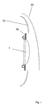
- the illustrations show the headlamps in side view, whereby only the affected elements are shown.
- FIG. 1 shows a headlight in which behind a headlight lens 20 around the actual projection lens 1 around in a corresponding orientation a circular ring element 2a is arranged.
- This annular element 2a is largely parallel to the lens base surface and also visually coated or colored accordingly, so that this results in an apparent increase in the lens diameter and thus the design of the vehicle headlamp.
- the annular element can, as shown in FIG. 1, be attached to the edge of the lens. Before that, another conventional cover element 10 can be arranged.
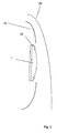
- FIG. 2 shows a headlamp in which the already existing cover element 10 of the lens 1 in the area around the lens is shaped correspondingly largely parallel to the lens base area, and likewise in the form of an annular area 2b.
- a corresponding coating in the affected annular area then provides for an optically enlarged diameter of the lens and thus an optically enlarged design without the additional space would be necessary because said elements are arranged anyway in the headlight.
- FIG 3 shows a headlamp according to the invention with a lens 1, which itself has a likewise annular edge contour 2c.
- This annular and integrally formed edge molding 2c of the projection lens 1 serves to illuminate the environment. That is, this edge portion merely radiates out the unfocused scattered light around the lens.
- projection lenses of this type also have the signal image function which results from the fact that the inner lens area forms the highly concentrated projection light cone and the outer edge area illuminates a diffuse area weakened in brightness, which provides the oncoming traffic with a glare-free signal image.
- lenses of this type also result in an optical enlargement of the lens surface, which also fulfills the stated purpose.
- FIG. 4 shows a headlight according to the invention in which an oversized lens 1 is used.
- the lens cut and the corresponding projection plane and projection parameters of the reflector mirror are dimensioned so to the lens that only an inner portion of the lens is used directly.
- the oversized edge region 2c serves only the optical magnification of the headlight design. Also, this design does not increase the length or depth in the headlight, because in this front area and larger lenses accordingly Have space available. The depth, however, is greater to realize a better look.
- the optics i. the cut of the lens in said used core area is again dimensioned exactly to the entire geometric dimension.
Abstract
Description
Die Erfindung betrifft einen Scheinwerfer nach dem Projektionstyp für Kraftfahrzeuge mit einem oder mehreren Leuchtmitteln, mindestens einem Reflektor sowie eine Linse gemäß Oberbegriff des Patentanspruches 1.The invention relates to a headlight according to the projection type for motor vehicles with one or more light sources, at least one reflector and a lens according to the preamble of
Scheinwerfer nach dem Projektionstyp sind im heutigen Kraftfahrzeugbau Standard. Dabei besteht der Scheinwerfer nach dem Projektionstyp aus einem Leuchtmittel, welches im Focus eines parabolischen Reflektors angeordnet ist. Die besagte Lampe, d.h. der Leuchtkörper muß dazu in entsprechend fixierter Position gehalten werden, wobei diese fixierte Position auch zum Reflektor relativ gesehen fixiert sein muß. Eine Verstellung des Lampenelementes heraus aus dem Fokus führt zu einer Defokusierung der eigentlichen Ausleuchtung bzw. des erzeugten Lichtkegels. Ferner sind für Scheinwerfer dieser Art auch Projektionslinsen notwendig, welche das aus dem Reflektor austretende Licht sammeln und in entsprechender Weise den Lichtkegel erzeugen.Headlamps according to the projection type are standard in today's motor vehicle construction. In this case, the headlight according to the projection type of a light source, which is arranged in the focus of a parabolic reflector. The said lamp, i. the luminous element must be kept in accordance with fixed position, this fixed position must be fixed relative to the reflector seen. An adjustment of the lamp element out of focus leads to a defocusing of the actual illumination or of the generated light cone. Furthermore, projection lenses are also necessary for headlamps of this type, which collect the light emerging from the reflector and produce the light cone in a corresponding manner.
Darüber hinaus sind bekanntermaßen innerhalb der Scheinwerferanordnung auch weitere Leuchtmittel wie eine Standlichtleuchte und dergleichen angeordnet. Dabei kommt es grundsätzlich darauf an, den Bauraum innerhalb der Scheinwerferanordnung kompakt zu nutzen. Ein besonders wichtiger Punkt ist die Bautiefe, die bei Scheinwerfern dieser Art natürlich von den geometrisch optischen Parametern wie Parabolfocus und Linsendurchmesser sowie Linsenkrümmung also Brennweite und dergleichen abhängt. Um eine bestimmte Ausleuchtung bzw. einen bestimmten Lichtkegel zu erzeugen, ist eine bestimmte Bautiefe minimal immer vorzugeben. Zum einen wird versucht, die äußere Gestalt des Scheinwerfers klein zu halten, was jedoch zu einem unzweckmäßigen unschönen optischen Design der Scheinwerferanordnung führt. Vielfach geht aus baulichen Gründen der Trend dahin, die Linsen im Durchmesser relativ klein zu gestalten. D.h. die verwendeten Linsen sind so klein daß sie den Betrachter bezüglich der erzielten Funktion fehlleiten.In addition, known bulbs such as a parking light and the like are known to be arranged within the headlamp assembly. It is basically important to use the space within the headlamp assembly compact. A particularly important point is the overall depth, which naturally depends on the geometrical optical parameters such as Parabolfocus and lens diameter and lens curvature so focal length and the like in headlamps of this kind. In order to produce a specific illumination or a specific cone of light, a certain basic depth is always minimal. On the one hand, attempts are made to keep the outer shape of the headlamp small, but this leads to an inappropriate unsightly optical design of the headlamp assembly. In many cases, for structural reasons, the trend is to make the lenses relatively small in diameter. That is, the lenses used are so small that they mislead the viewer regarding the achieved function.
Hinsichtlich eines genannten allgemeinen Scheinwerfers nach dem Projektionstyp ist ein solcher aus der DE 3516813 bekannt. Der Scheinwerfer nach dem Projektionstyp besteht dabei aus einer Sammellinse mit ringförmigem Gestell. Im wesentlichen hat dieses Gestell nur tragende Funktionen. Eine weitergehende Funktion auch optischer Art kommt diesem Gestell nicht zu.With regard to a said general headlight according to the projection type, such is known from DE 3516813. The headlamp according to the projection type consists of a converging lens with an annular frame. In essence, this frame has only supporting functions. A further function also optical kind does not apply to this frame.
Aus der gattungsbildenden DE 196 21 254 A1 ist ein Scheinwerfer für Fahrzeuge nach dem Projektionstyp bekannt. Er umfasst eine Lichtquelle, einen Reflektor und eine Linse. Die Linse ist in einem Trägerelement gehalten, das die Linse zumindest über einen Teil ihres Umfangs umgibt. Das Trägerelement ist am Vorderrand des Reflektors befestigt, weist dann in Lichtaustrittsrichtung einen kegelstumpfförmigen Abschnitt auf und nimmt schließlich die Linse auf. Die Linse liegt dabei mit ihrem Rand an einer Stufe des Trägerelements anFrom the generic DE 196 21 254 A1 a headlamp for vehicles by the projection type is known. It includes a light source, a reflector and a lens. The lens is held in a support member surrounding the lens over at least a portion of its circumference. The carrier element is attached to the front edge of the reflector, then has a frustoconical portion in the light exit direction and finally receives the lens. The lens rests with its edge on a step of the support element
Der Erfindung liegt daher die Aufgabe zugrunde bei bauraumminimierten Scheinwerfern der gattungsgemäßen Art eine optische Vergrößerung des Scheinwerferdesigns zu erreichen ohne die Baulänge, bzw. die Bautiefe als solches zu vergrößern bzw. vergrößern zu müssen.The invention is therefore based on the object with space-minimized headlamps of the generic type to achieve an optical magnification of the headlamp design without the length, or the depth as such to enlarge or enlarge.
Die gestellte Aufgabe wird bei einem gattungsgemäßen Scheinwerfer nach dem Projektionstyp für Kraftfahrzeuge erfindungsgemäß durch die Merkmale des Anspruches 1 gelöst. Bei dem Scheinwerfer ist der optisch aktive, d.h. direkt ausgeleuchtete Linsendurchmesser um einen optisch nicht aktiven bzw. nicht ausgeleuchteten und randseitig einstückig an die Linse angeformten Linsenrandbereich erweitert.The object is achieved according to the invention in a generic headlight according to the projection type for motor vehicles by the features of
Hierdurch erscheint die eigentliche Scheinwerferanordnung nahe dem Linsenbereich vergrößert, obwohl keine größere Linse verwendet wird. Zur optischen Vergrößerung wird dabei jedoch kein Element verwendet, welches einen größeren Bauraum bedingt. Das Wesen der Erfindung besteht so im wesentlichen darin, daß die optische Vergrößerung durch ein Element bewerkstelligt wird, welches ohnehin im Bauraum des Scheinwerfers vorhanden und notwendig ist, aber nunmehr so ausgebildet und plaziert ist, daß es den oben genannten Zweck erfüllt.As a result, the actual headlamp assembly near the lens area appears enlarged, although no larger lens is used. For optical magnification but no element is used, which requires a larger space. The essence of the invention consists essentially in the fact that the optical magnification is accomplished by an element which is present anyway in the space of the headlamp and necessary, but is now designed and placed so that it fulfills the above purpose.
Der Linsenrandbereich kann überdies zur Umfeldausleuchtung und zur optischen Vergrößerung der Linse als solches dienen.The lens edge region can also serve for ambient illumination and for optical enlargement of the lens as such.
In weitergehender vorteilhafter Ausgestaltung ist angegeben, daß ein optisch nicht aktiver nicht ausgeleuchteter Randbereich durch Überdimensionierung des Linsendurchmessers gebildet ist. Der Linsenkörper ist dabei hinsichtlich seines Durchmesser so weit überdimensioniert, daß er aber immer noch in den vorgegebenen Bauraum hineinpaßt, also diesen nicht zwingend vergrößert, weil der genutzte Durchmesser lediglich eine brennweitenbedingte Position hat. Der optisch nicht aktive Randbereich hat somit keinen Brennweitenbezug. Zum anderen ist die auf diese Weise überdimensionierte Linse aber nicht über die volle Fläche hin ausgeleuchtet, so daß der nicht ausgeleuchtete Randbereich lediglich der optischen Vergrößerung des Linsendurchmessers und damit der Scheinwerferoptik bzw. dem Scheinwerferdesign dient. Es kann über den besagten Randbereich auch Restlicht abgestrahlt werden, was aber nicht zwingend ist. Ausführungsformen der Erfindung sind in der Zeichnung dargestellt und nachfolgend näher beschrieben.In a further advantageous embodiment, it is stated that an optically non-active non-illuminated edge region is formed by over-dimensioning the lens diameter. The lens body is so far oversized in terms of its diameter, but that it still fits into the given space, so this is not necessarily increased, because the diameter used only has a focal length condition. The optically non-active edge region thus has no reference to the focal length. On the other hand, the over-dimensioned lens in this way is not illuminated over the entire area, so that the non-illuminated edge area only serves the optical magnification of the lens diameter and thus the headlight optics or the headlamp design. It can be radiated over the said edge area and residual light, but this is not mandatory. Embodiments of the invention are illustrated in the drawings and described in more detail below.
Es zeigt
- Figur 1:
- Linse mit einem an oder aufgesetzten Kreisringelement.
- Figur 2:
- Projektionslinse mit einem halterungsseitigen Blech in entsprechender Konturierung und Mattierung.
- Figur 3:
- Linse mit kreisringförmiger Anformung am Außenrand zur Umfeldbeleuchtung gemäß einem ersten Ausführungsbeispiel der Erfindung.
- Figur 4:
- Überdimensionierte Linse gemäß einem zweiten Ausführungsbeispiel der Erfindung.
- FIG. 1:
- Lens with an attached or attached circular ring element.
- FIG. 2:
- Projection lens with a holder-side plate in appropriate contouring and matting.
- FIG. 3:
- Lens with annular Anformung on the outer edge to the ambient lighting according to a first embodiment of the invention.
- FIG. 4:
- Oversized lens according to a second embodiment of the invention.
Die Abbildungen zeigen die Scheinwerfer in Seitenansicht, wobei nur die betroffenen Elemente dargestellt sind.The illustrations show the headlamps in side view, whereby only the affected elements are shown.
Figur 1 zeigt einen Scheinwerfer, bei welchem hinter einem Scheinwerferglas 20 um die eigentliche Projektionslinse 1 herum in entsprechender Ausrichtung ein Kreisringelement 2a angeordnet ist. Dieses Kreisringelement 2a ist dabei weitestgehend parallel zur Linsenbasisfläche und auch optisch entsprechend beschichtet oder eingefärbt, so daß sich hierdurch eine scheinbare Vergrößerung des Linsendurchmessers und damit des Designs des Fahrzeugscheinwerfers ergibt. Das Kreisringelement kann, wie dies Figur 1 zeigt, auf den Rand der Linse aufgesteckt sein. Davor kann ein weiteres herkömmliches Abdeckelement 10 angeordnet sein.FIG. 1 shows a headlight in which behind a
Figur 2 zeigt einen Scheinwerfer, bei welchem das bereits vorhandene Abdeckelement 10 der Linse 1 im Bereich um die Linse herum entsprechend weitestgehend parallel zur Linsenbasisfläche geformt ist, und zwar ebenfalls in Form eines kreisringförmigen Bereiches 2b. Eine entsprechende Beschichtung im betroffenen Kreisringbereich sorgt dann für einen optisch vergrößerten Durchmesser der Linse und damit einem optisch vergrößerten Design ohne das zusätzlicher Bauraum nötig wäre, weil die besagten Elemente ohnehin im Scheinwerfer angeordnet sind.FIG. 2 shows a headlamp in which the already
Figur 3 zeigt einen erfindungsgemäßen Scheinwerfer mit einer Linse 1, welche selbst eine ebenfalls kreisringförmige Randkontur 2c aufweist. Diese kreisringförmige und einstückig angeformte Randanformung 2c der Projektionslinse 1 dient zur Ausleuchtung des Umfeldes. D.h., daß dieser Randbereich lediglich das nicht fokussierte Streulicht um die Linse herum bzw. aus diesem Bereich heraus abstrahlt. Projektionslinsen dieser Art haben neben der eigentlichen Ausleuchtfunktion auch noch die Signalbildfunktion die sich daraus ergibt, daß der innere Linsenbereich den stark gebündelten Projektionslichtkegel bildet und der Außenrandbereich eine diffuse in der Helligkeit abgeschwächte Fläche ausleuchtet, die dem entgegenkommenden Verkehr ein blendfreies Signalbild bietet.Figure 3 shows a headlamp according to the invention with a
Linsen dieser Art führen neben dieser Funktion natürlich auch dazu, daß sich eine optische Vergrößerung der Linsenfläche ergibt, was ebenso den besagten Zweck erfüllt.Of course, in addition to this function, lenses of this type also result in an optical enlargement of the lens surface, which also fulfills the stated purpose.
Figur 4 zeigt einen erfindungsgemäßen Scheinwerfer bei welcher eine überdimensionierte Linse 1 verwendet wird. Der Linsenschliff und die entsprechende Projektionsebene und Projektionsparameter des Reflektorspiegels sind dabei so zur Linse bemessen, daß nur ein innerer Teilbereich der Linse direkt genutzt wird. Der überdimensionierte Randbereich 2c dient dabei lediglich der optischen Vergrößerung des Scheinwerferdesigns. Auch diese Bauform erhöht die Baulänge bzw. -tiefe im Scheinwerfer nicht, weil in diesem vorderen Bereich auch größere Linsen entsprechend Platz zur Verfügung haben. Die Bautiefe hingegen wird zur Realisierung einer besseren Optik größer.FIG. 4 shows a headlight according to the invention in which an
Die Optik, d.h. der Schliff der Linse im besagten genutzten Kernbereich ist dabei auf die gesamte geometrische Abmessung wiederum genau bemessen.The optics, i. the cut of the lens in said used core area is again dimensioned exactly to the entire geometric dimension.
Claims (3)
- Headlight of the projection type for motor vehicles, having one or more lamps, having at least one reflector and also having a lens (1), characterized in that the optically active, directly illuminated lens diameter is extended by an optically inactive lens edge region (2c, 2d) which is not directly illuminated by the focus light and is integrally formed on the edge of the lens.
- Headlight of the projection type for motor vehicles according to Claim 1, characterized in that the lens edge region (2c, 2d) is used to illuminate the surrounding area and for visual enlargement purposes.
- Headlight of the projection type for motor vehicles according to Claim 1 or 2, characterized in that the optically inactive lens edge region (2d) which is not illuminated is formed by making the lens diameter oversize.
Applications Claiming Priority (2)
| Application Number | Priority Date | Filing Date | Title |
|---|---|---|---|
| DE19829343A DE19829343A1 (en) | 1998-07-01 | 1998-07-01 | Headlight arrangement according to the projection type for motor vehicles |
| DE19829343 | 1998-07-01 |
Publications (3)
| Publication Number | Publication Date |
|---|---|
| EP0969246A2 EP0969246A2 (en) | 2000-01-05 |
| EP0969246A3 EP0969246A3 (en) | 2001-10-17 |
| EP0969246B1 true EP0969246B1 (en) | 2007-04-11 |
Family
ID=7872596
Family Applications (1)
| Application Number | Title | Priority Date | Filing Date |
|---|---|---|---|
| EP99111394A Expired - Lifetime EP0969246B1 (en) | 1998-07-01 | 1999-06-11 | Headlamp device of the projection type for motor vehicles |
Country Status (3)
| Country | Link |
|---|---|
| EP (1) | EP0969246B1 (en) |
| AT (1) | ATE359482T1 (en) |
| DE (2) | DE19829343A1 (en) |
Cited By (1)
| Publication number | Priority date | Publication date | Assignee | Title |
|---|---|---|---|---|
| DE102008038999A1 (en) | 2008-08-21 | 2010-02-25 | Hella Kgaa Hueck & Co. | Projection lens for headlight of motor vehicle, has optically active area for light refraction and surrounding area formed on edge-side away from optical axis for mechanical inclusion of projection lens |
Families Citing this family (3)
| Publication number | Priority date | Publication date | Assignee | Title |
|---|---|---|---|---|
| DE102004011090B4 (en) * | 2004-03-06 | 2007-01-04 | Daimlerchrysler Ag | Headlights for vehicles |
| DE102006060141A1 (en) | 2006-12-18 | 2008-06-26 | Docter Optics Gmbh | Headlight lens for a motor vehicle headlight |
| DE102010061460A1 (en) * | 2010-12-22 | 2012-06-28 | Hella Kgaa Hueck & Co. | Projection module for vehicle head-light, has light guiding element and light source assigned to light guiding element, where lens up-streams light guiding element in light emission direction |
Family Cites Families (8)
| Publication number | Priority date | Publication date | Assignee | Title |
|---|---|---|---|---|
| US1393573A (en) * | 1920-10-21 | 1921-10-11 | John A Ritter | Headlamp |
| DE1009506B (en) * | 1956-04-30 | 1957-05-29 | Westfaelische Metall Industrie | Automotive headlights |
| US3082320A (en) * | 1959-05-01 | 1963-03-19 | Singer Mfg Co | Lighting fixtures |
| FR2550847B1 (en) * | 1983-08-18 | 1988-07-01 | Cibie Projecteurs | ELLIPTICAL REFLECTOR WITH CUT BEAM FOR MOTOR VEHICLE |
| DE3516813A1 (en) * | 1985-05-10 | 1986-11-13 | Hella KG Hueck & Co, 4780 Lippstadt | Dimmed vehicle headlights |
| DE3640773A1 (en) * | 1986-11-28 | 1988-06-09 | Hella Kg Hueck & Co | HEADLIGHTS FOR VEHICLES ACCORDING TO THE PROJECTION PRINCIPLE |
| AT398337B (en) * | 1988-04-27 | 1994-11-25 | Zizala Lichtsysteme Gmbh | Vehicle headlight (headlamp) |
| DE19621254B4 (en) * | 1996-05-25 | 2007-07-12 | Automotive Lighting Reutlingen Gmbh | vehicle headlights |
-
1998
- 1998-07-01 DE DE19829343A patent/DE19829343A1/en not_active Withdrawn
-
1999
- 1999-06-11 AT AT99111394T patent/ATE359482T1/en not_active IP Right Cessation
- 1999-06-11 EP EP99111394A patent/EP0969246B1/en not_active Expired - Lifetime
- 1999-06-11 DE DE59914287T patent/DE59914287D1/en not_active Expired - Fee Related
Cited By (1)
| Publication number | Priority date | Publication date | Assignee | Title |
|---|---|---|---|---|
| DE102008038999A1 (en) | 2008-08-21 | 2010-02-25 | Hella Kgaa Hueck & Co. | Projection lens for headlight of motor vehicle, has optically active area for light refraction and surrounding area formed on edge-side away from optical axis for mechanical inclusion of projection lens |
Also Published As
| Publication number | Publication date |
|---|---|
| EP0969246A3 (en) | 2001-10-17 |
| DE59914287D1 (en) | 2007-05-24 |
| EP0969246A2 (en) | 2000-01-05 |
| DE19829343A1 (en) | 2000-01-05 |
| ATE359482T1 (en) | 2007-05-15 |
Similar Documents
| Publication | Publication Date | Title |
|---|---|---|
| DE69830657T2 (en) | VEHICLE LIGHT WITH REDUCED IRIS | |
| DE10144637B4 (en) | vehicle light | |
| EP0225313B1 (en) | Vehicle lights | |
| DE19853402B4 (en) | Headlamp with hyperbolic reflector and headlamp insert with such a headlamp | |
| EP2420728B1 (en) | Projection headlamp with targeted weakened light intensity gradients at the light-dark border | |
| DE102008036845B4 (en) | lighting device | |
| DE102007037309A1 (en) | Infrared light bulb for vehicles | |
| DE2726951C2 (en) | Headlights for automobiles | |
| DE112019004392T5 (en) | Low beam III zone lighting module, vehicle headlights and vehicle | |
| DE10161922B4 (en) | vehicle headlights | |
| DE19519655B4 (en) | Lighting device arranged on a front part of a vehicle | |
| EP0969246B1 (en) | Headlamp device of the projection type for motor vehicles | |
| DE10052653A1 (en) | Lighting arrangement for motor vehicles | |
| DE19946351B4 (en) | Headlights for vehicles | |
| DE19805216A1 (en) | Vehicle headlamp with two filaments forming beams with and without light dark boundary | |
| EP0974786B1 (en) | Headlamp of the projector type for vehicles | |
| DE19829343A9 (en) | Projection-type headlamp assembly for automobiles | |
| DE1925277A1 (en) | Light, in particular rear or safety light | |
| DE10012634B4 (en) | Motor vehicle headlight with active rear wall area | |
| EP1126211B1 (en) | Projecting headlight for motor vehicle | |
| DE3933411C2 (en) | ||
| DE19829345B4 (en) | Projection headlights for motor vehicles | |
| DE19921511A1 (en) | Headlights for vehicles | |
| DE10222129A1 (en) | Vehicle lamp with a lamp and a hollow or cup-shaped reflector | |
| DE10110132A1 (en) | Headlamp for road vehicle has cylindrical lens with focal line comprising row of multiple focal points, on axis perpendicular to center of cylindrical lens, parabolic or elliptical reflector |
Legal Events
| Date | Code | Title | Description |
|---|---|---|---|
| PUAI | Public reference made under article 153(3) epc to a published international application that has entered the european phase |
Free format text: ORIGINAL CODE: 0009012 |
|
| AK | Designated contracting states |
Kind code of ref document: A2 Designated state(s): AT BE CH CY DE DK ES FI FR GB GR IE IT LI LU MC NL PT SE Kind code of ref document: A2 Designated state(s): AT DE ES FR GB IT PT SE |
|
| AX | Request for extension of the european patent |
Free format text: AL;LT;LV;MK;RO;SI |
|
| PUAL | Search report despatched |
Free format text: ORIGINAL CODE: 0009013 |
|
| AK | Designated contracting states |
Kind code of ref document: A3 Designated state(s): AT BE CH CY DE DK ES FI FR GB GR IE IT LI LU MC NL PT SE |
|
| AX | Request for extension of the european patent |
Free format text: AL;LT;LV;MK;RO;SI |
|
| 17P | Request for examination filed |
Effective date: 20020417 |
|
| AKX | Designation fees paid |
Free format text: AT DE ES FR GB IT PT SE |
|
| 17Q | First examination report despatched |
Effective date: 20051222 |
|
| GRAP | Despatch of communication of intention to grant a patent |
Free format text: ORIGINAL CODE: EPIDOSNIGR1 |
|
| RIC1 | Information provided on ipc code assigned before grant |
Ipc: F21S 8/12 20060101ALI20060911BHEP Ipc: F21V 17/00 20060101ALI20060911BHEP Ipc: F21V 5/04 20060101AFI20060911BHEP |
|
| GRAS | Grant fee paid |
Free format text: ORIGINAL CODE: EPIDOSNIGR3 |
|
| GRAA | (expected) grant |
Free format text: ORIGINAL CODE: 0009210 |
|
| AK | Designated contracting states |
Kind code of ref document: B1 Designated state(s): AT DE ES FR GB IT PT SE |
|
| REG | Reference to a national code |
Ref country code: GB Ref legal event code: FG4D Free format text: NOT ENGLISH |
|
| REF | Corresponds to: |
Ref document number: 59914287 Country of ref document: DE Date of ref document: 20070524 Kind code of ref document: P |
|
| PG25 | Lapsed in a contracting state [announced via postgrant information from national office to epo] |
Ref country code: SE Free format text: LAPSE BECAUSE OF FAILURE TO SUBMIT A TRANSLATION OF THE DESCRIPTION OR TO PAY THE FEE WITHIN THE PRESCRIBED TIME-LIMIT Effective date: 20070711 |
|
| PG25 | Lapsed in a contracting state [announced via postgrant information from national office to epo] |
Ref country code: ES Free format text: LAPSE BECAUSE OF FAILURE TO SUBMIT A TRANSLATION OF THE DESCRIPTION OR TO PAY THE FEE WITHIN THE PRESCRIBED TIME-LIMIT Effective date: 20070722 |
|
| ET | Fr: translation filed | ||
| PG25 | Lapsed in a contracting state [announced via postgrant information from national office to epo] |
Ref country code: PT Free format text: LAPSE BECAUSE OF FAILURE TO SUBMIT A TRANSLATION OF THE DESCRIPTION OR TO PAY THE FEE WITHIN THE PRESCRIBED TIME-LIMIT Effective date: 20070911 |
|
| GBV | Gb: ep patent (uk) treated as always having been void in accordance with gb section 77(7)/1977 [no translation filed] |
Effective date: 20070411 |
|
| PLBE | No opposition filed within time limit |
Free format text: ORIGINAL CODE: 0009261 |
|
| STAA | Information on the status of an ep patent application or granted ep patent |
Free format text: STATUS: NO OPPOSITION FILED WITHIN TIME LIMIT |
|
| 26N | No opposition filed |
Effective date: 20080114 |
|
| PG25 | Lapsed in a contracting state [announced via postgrant information from national office to epo] |
Ref country code: IT Free format text: LAPSE BECAUSE OF FAILURE TO SUBMIT A TRANSLATION OF THE DESCRIPTION OR TO PAY THE FEE WITHIN THE PRESCRIBED TIME-LIMIT Effective date: 20070411 Ref country code: GB Free format text: LAPSE BECAUSE OF FAILURE TO SUBMIT A TRANSLATION OF THE DESCRIPTION OR TO PAY THE FEE WITHIN THE PRESCRIBED TIME-LIMIT Effective date: 20070411 |
|
| PG25 | Lapsed in a contracting state [announced via postgrant information from national office to epo] |
Ref country code: AT Free format text: LAPSE BECAUSE OF NON-PAYMENT OF DUE FEES Effective date: 20070611 |
|
| PGFP | Annual fee paid to national office [announced via postgrant information from national office to epo] |
Ref country code: DE Payment date: 20080630 Year of fee payment: 10 |
|
| PGFP | Annual fee paid to national office [announced via postgrant information from national office to epo] |
Ref country code: FR Payment date: 20080606 Year of fee payment: 10 |
|
| REG | Reference to a national code |
Ref country code: FR Ref legal event code: ST Effective date: 20100226 |
|
| PG25 | Lapsed in a contracting state [announced via postgrant information from national office to epo] |
Ref country code: FR Free format text: LAPSE BECAUSE OF NON-PAYMENT OF DUE FEES Effective date: 20090630 |
|
| PG25 | Lapsed in a contracting state [announced via postgrant information from national office to epo] |
Ref country code: DE Free format text: LAPSE BECAUSE OF NON-PAYMENT OF DUE FEES Effective date: 20100101 |