EP0969203B1 - Coupling system between engine head, injector and fuel manifold - Google Patents
Coupling system between engine head, injector and fuel manifold Download PDFInfo
- Publication number
- EP0969203B1 EP0969203B1 EP99112339A EP99112339A EP0969203B1 EP 0969203 B1 EP0969203 B1 EP 0969203B1 EP 99112339 A EP99112339 A EP 99112339A EP 99112339 A EP99112339 A EP 99112339A EP 0969203 B1 EP0969203 B1 EP 0969203B1
- Authority
- EP
- European Patent Office
- Prior art keywords
- injector
- seat
- coupling system
- annular shoulder
- fact
- Prior art date
- Legal status (The legal status is an assumption and is not a legal conclusion. Google has not performed a legal analysis and makes no representation as to the accuracy of the status listed.)
- Expired - Lifetime
Links
- 239000000446 fuel Substances 0.000 title claims description 38
- 238000010168 coupling process Methods 0.000 title claims description 27
- 238000005859 coupling reaction Methods 0.000 title claims description 27
- 230000008878 coupling Effects 0.000 title claims description 24
- 238000002485 combustion reaction Methods 0.000 claims description 14
- 239000007921 spray Substances 0.000 claims description 4
- 230000000295 complement effect Effects 0.000 claims 1
- 238000012986 modification Methods 0.000 description 1
- 230000004048 modification Effects 0.000 description 1
- 238000012856 packing Methods 0.000 description 1
- 230000002093 peripheral effect Effects 0.000 description 1
Images
Classifications
-
- F—MECHANICAL ENGINEERING; LIGHTING; HEATING; WEAPONS; BLASTING
- F02—COMBUSTION ENGINES; HOT-GAS OR COMBUSTION-PRODUCT ENGINE PLANTS
- F02M—SUPPLYING COMBUSTION ENGINES IN GENERAL WITH COMBUSTIBLE MIXTURES OR CONSTITUENTS THEREOF
- F02M55/00—Fuel-injection apparatus characterised by their fuel conduits or their venting means; Arrangements of conduits between fuel tank and pump F02M37/00
- F02M55/02—Conduits between injection pumps and injectors, e.g. conduits between pump and common-rail or conduits between common-rail and injectors
- F02M55/025—Common rails
-
- F—MECHANICAL ENGINEERING; LIGHTING; HEATING; WEAPONS; BLASTING
- F02—COMBUSTION ENGINES; HOT-GAS OR COMBUSTION-PRODUCT ENGINE PLANTS
- F02M—SUPPLYING COMBUSTION ENGINES IN GENERAL WITH COMBUSTIBLE MIXTURES OR CONSTITUENTS THEREOF
- F02M61/00—Fuel-injectors not provided for in groups F02M39/00 - F02M57/00 or F02M67/00
- F02M61/14—Arrangements of injectors with respect to engines; Mounting of injectors
-
- F—MECHANICAL ENGINEERING; LIGHTING; HEATING; WEAPONS; BLASTING
- F02—COMBUSTION ENGINES; HOT-GAS OR COMBUSTION-PRODUCT ENGINE PLANTS
- F02M—SUPPLYING COMBUSTION ENGINES IN GENERAL WITH COMBUSTIBLE MIXTURES OR CONSTITUENTS THEREOF
- F02M69/00—Low-pressure fuel-injection apparatus ; Apparatus with both continuous and intermittent injection; Apparatus injecting different types of fuel
- F02M69/46—Details, component parts or accessories not provided for in, or of interest apart from, the apparatus covered by groups F02M69/02 - F02M69/44
- F02M69/462—Arrangement of fuel conduits, e.g. with valves for maintaining pressure in the pipes after the engine being shut-down
- F02M69/465—Arrangement of fuel conduits, e.g. with valves for maintaining pressure in the pipes after the engine being shut-down of fuel rails
-
- F—MECHANICAL ENGINEERING; LIGHTING; HEATING; WEAPONS; BLASTING
- F02—COMBUSTION ENGINES; HOT-GAS OR COMBUSTION-PRODUCT ENGINE PLANTS
- F02B—INTERNAL-COMBUSTION PISTON ENGINES; COMBUSTION ENGINES IN GENERAL
- F02B75/00—Other engines
- F02B75/12—Other methods of operation
- F02B2075/125—Direct injection in the combustion chamber for spark ignition engines, i.e. not in pre-combustion chamber
-
- F—MECHANICAL ENGINEERING; LIGHTING; HEATING; WEAPONS; BLASTING
- F02—COMBUSTION ENGINES; HOT-GAS OR COMBUSTION-PRODUCT ENGINE PLANTS
- F02M—SUPPLYING COMBUSTION ENGINES IN GENERAL WITH COMBUSTIBLE MIXTURES OR CONSTITUENTS THEREOF
- F02M2200/00—Details of fuel-injection apparatus, not otherwise provided for
- F02M2200/85—Mounting of fuel injection apparatus
- F02M2200/856—Mounting of fuel injection apparatus characterised by mounting injector to fuel or common rail, or vice versa
-
- Y—GENERAL TAGGING OF NEW TECHNOLOGICAL DEVELOPMENTS; GENERAL TAGGING OF CROSS-SECTIONAL TECHNOLOGIES SPANNING OVER SEVERAL SECTIONS OF THE IPC; TECHNICAL SUBJECTS COVERED BY FORMER USPC CROSS-REFERENCE ART COLLECTIONS [XRACs] AND DIGESTS
- Y02—TECHNOLOGIES OR APPLICATIONS FOR MITIGATION OR ADAPTATION AGAINST CLIMATE CHANGE
- Y02T—CLIMATE CHANGE MITIGATION TECHNOLOGIES RELATED TO TRANSPORTATION
- Y02T10/00—Road transport of goods or passengers
- Y02T10/10—Internal combustion engine [ICE] based vehicles
- Y02T10/12—Improving ICE efficiencies
Definitions
- the present invention concerns a coupling system between the engine head, the injector and the fuel manifold.
- Such injectors receive the fuel under high pressure from a fuel manifold which extends above the actual injectors.
- the focal point of fuel supply groups described above is the connection between the injector and the fuel manifold which has to be achieved in such a manner as to exclude whatsoever fuel leakage.
- Such a connection nevertheless calls for design details which by frequently causing misalignment between the injector which projects from the recessed seating in the engine head and the fuel manifold located above the head, involves constraints by interposing between the injector and the fuel manifold a connection seal able to prevent any misalignment.
- Figure 1 illustrates a known coupling system between the engine head, the injector and the fuel manifold, in which the injector 100 is locked inside the seating 101 recessed in the head 102 by means of a securing strap 103 bolted into the head 102.
- the upper end of the injector 100 is connected to the fuel manifold 104 by means of a rigid bush 105 which has a first end placed on the injector 100 and a second end inserted into the inside of a corresponding seat 106 formed in the actual fuel manifold 104.
- the rigid bush 105 is coupled to the injector 100 and to the fuel manifold 104 with a certain clearance in such a manner as to make good the eventual unseating, and is held secured to the fuel manifold 104 by means of a flexible locking component 107 located on the outside of the rigid bush 105.
- the seal is ensured by means of two annular packings positioned to coincide with the two ends of the rigid bush 105.
- the purpose of the present invention is therefore to achieve a coupling system of an economical nature and basically more secure between the injector and the fuel manifold.
- a coupling system is achieved between the engine head, the injector and the fuel manifold in which the engine head has a seat able to accommodate the said injector; the system being characterised by the fact that the injector is coupled with the seat by way of a ball-coupling which allows orientation as required by the injector inside the said seat.
- the injector able to provide on demand a specific quantity of fuel inside the combustion chamber of the internal combustion engine, and the fuel manifold inside which the fuel is accumulated under high pressure to be directed towards the combustion chamber of the internal combustion engine.
- the head 1, the injector 2 and the fuel manifold 3 are interconnected in such a manner that the fuel under high pressure entering the fuel manifold 3 is able to enter the combustion chamber of the engine which in the example shown here, is partly arranged inside the head 1, and hereinafter appears under reference 4.
- the head 1 of the internal combustion engine has a seat 5 communicating with the combustion chamber 4 of the internal combustion engine.
- the said seat 5 extends in the head 1 coaxially with axis X perpendicular with the example shown for the outer surface of the head 1, and has an upper portion 5a of mainly cylindrical form, able to be engaged by the central body 2a of the injector 2; a lower portion 5b of essentially truncated cone form, communicating with the combustion chamber 4 and able to be engaged by the end portion 2b of the injector 2 in which is recessed the spray nozzle; and finally an intermediate portion 5c connecting the portions 5a and 5b one with the other.
- the upper portion 5a and the intermediate portion 5c are separated from each other by an annular shoulder 6 coaxial with axis X, having the form of a spherical crown with a recess turned towards the lower portion 5b, or towards the inside of the head 1.
- the inside of the spherical surface belonging to the spherical crown defined by the annular shoulder 6 is located along axis X, coinciding with the centre of the annular seat 7 resented by the injector 2 on the outer surface of the end portion 2b, immediately pstream of the spray nozzle.
- the annular shoulder 6 is formed complete with an inserted bush 8 coaxial with axis X, inside the upper portion 5a of the seat 5. Obviously it is also possible to achieve an annular shoulder 6 directly on the side wall of the seat 5.
- the injector in turn is provided with an annular shoulder 9 extending coaxially with axis A of the injector 2, on the outside of the central body 2a of the injector 2.
- the said annular shoulder 9 provides a shape additional to the annular shoulder 6 in such a manner as to be located so as to bear thereupon it, the latter defining a spherical coupling 10.
- annular shoulder 9 is achieved by means of a keyed bush 11, coaxial with axis A, on the outside of the central body 2a of the injector 2.
- the annular shoulder 9 can be achieved directly on the outer lateral surface of the central body 2a of the injector 2.
- the spherical coupling existing between the injector 2 and the seat 5 allows a variation at will of the position of the injector 2 on the inside of the seat 5.
- the ball coupling 10 allows the injector 2 to be inclined in one way or the other inside the seat 5, in such a way that the axis A of the injector 2 is inclined by a specific angle defined in relation to axis X of the seat 5.
- the fuel manifold 3 extends above the head 1 coaxially with an axis Y, preferably though not necessarily, parallel with the outer surface 1a of the head 1, and rigidly secured to the head 1 of the engine by means of securing components not illustrated here, and has a connecting bush 12 which extends towards the injector 2 located in the seat 5 of the head 1.
- the said bush 12 is designed to admit internally a part of the end portion 2c of the injector 2 which projects externally from the seat 5.
- annular seal 13 located on the end portion 2c of the injector 2 prevents fuel from escaping under high pressure.
- Locking means 15 are finally provided to retain the injector 2 inside the seat 5 with the annular shoulder 9 bearing against the annular shoulder 6 in such a manner as to achieve the ball coupling 10.
- such locking means 15 consist of a compressed retaining spring, which is located between the injector 2 and the fuel manifold 3 in such a manner as to squeeze the injector 2 inside the seat 5.
- the said retaining spring is housed inside the bush 12 in such a manner as to have a first end bearing against the end portion 2c of the injector 2, and a second end bearing against the bottom of the bush 12.
- the retaining spring is a rated spring perfectly fitting the injector 2 in such a way as to present a first end bearing against the central body 2a of the injector 2, and a second end bearing against the peripheral edge 12a of the bush 11.
- the rated spring is without centre rib so as not to interfere with the pin of the injector 2.
Landscapes
- Engineering & Computer Science (AREA)
- Chemical & Material Sciences (AREA)
- Combustion & Propulsion (AREA)
- Mechanical Engineering (AREA)
- General Engineering & Computer Science (AREA)
- Fuel-Injection Apparatus (AREA)
Description
- The present invention concerns a coupling system between the engine head, the injector and the fuel manifold.
- As it is well known, on internal combustion engines at present available in commerce the fuel supply to the combustion chamber is increasingly more frequently achieved by means of one or several injectors housed inside suitable seats recessed into the engine head.
- Such injectors receive the fuel under high pressure from a fuel manifold which extends above the actual injectors.
- The focal point of fuel supply groups described above is the connection between the injector and the fuel manifold which has to be achieved in such a manner as to exclude whatsoever fuel leakage. Such a connection nevertheless calls for design details which by frequently causing misalignment between the injector which projects from the recessed seating in the engine head and the fuel manifold located above the head, involves constraints by interposing between the injector and the fuel manifold a connection seal able to prevent any misalignment.
- Figure 1 illustrates a known coupling system between the engine head, the injector and the fuel manifold, in which the
injector 100 is locked inside theseating 101 recessed in thehead 102 by means of asecuring strap 103 bolted into thehead 102. The upper end of theinjector 100 is connected to thefuel manifold 104 by means of arigid bush 105 which has a first end placed on theinjector 100 and a second end inserted into the inside of acorresponding seat 106 formed in theactual fuel manifold 104. Therigid bush 105 is coupled to theinjector 100 and to thefuel manifold 104 with a certain clearance in such a manner as to make good the eventual unseating, and is held secured to thefuel manifold 104 by means of aflexible locking component 107 located on the outside of therigid bush 105. The seal is ensured by means of two annular packings positioned to coincide with the two ends of therigid bush 105. - It is manifest that a connection between injector and fuel manifold such as is shown in figure 1 is extremely costly, greatly complicates the assembly of the fuel supply group on the engine, and finally doubles the number of possible fuel leakage points.
- The purpose of the present invention is therefore to achieve a coupling system of an economical nature and basically more secure between the injector and the fuel manifold.
- According to the present invention a coupling system is achieved between the engine head, the injector and the fuel manifold in which the engine head has a seat able to accommodate the said injector; the system being characterised by the fact that the injector is coupled with the seat by way of a ball-coupling which allows orientation as required by the injector inside the said seat.
- The present invention is now described with reference to the appended
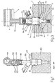
drawings - figure 2 illustrates with parts in section and parts removed for greater clarity, a coupling system between the engine head, the injector and the fuel manifold achieved according to the details of the invention.
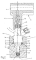
- figure 3 is a variation in the coupling system between the engine head, the injector and the fuel manifold illustrated in figure 2
-
- With regard to
reference numbers - The head 1, the
injector 2 and thefuel manifold 3 are interconnected in such a manner that the fuel under high pressure entering thefuel manifold 3 is able to enter the combustion chamber of the engine which in the example shown here, is partly arranged inside the head 1, and hereinafter appears underreference 4. - To house the
injector 2, the head 1 of the internal combustion engine has aseat 5 communicating with thecombustion chamber 4 of the internal combustion engine. - The said
seat 5 extends in the head 1 coaxially with axis X perpendicular with the example shown for the outer surface of the head 1, and has anupper portion 5a of mainly cylindrical form, able to be engaged by thecentral body 2a of theinjector 2; alower portion 5b of essentially truncated cone form, communicating with thecombustion chamber 4 and able to be engaged by theend portion 2b of theinjector 2 in which is recessed the spray nozzle; and finally anintermediate portion 5c connecting theportions - With regard to figure 2, the
upper portion 5a and theintermediate portion 5c are separated from each other by anannular shoulder 6 coaxial with axis X, having the form of a spherical crown with a recess turned towards thelower portion 5b, or towards the inside of the head 1.The inside of the spherical surface belonging to the spherical crown defined by theannular shoulder 6 is located along axis X, coinciding with the centre of theannular seat 7 resented by theinjector 2 on the outer surface of theend portion 2b, immediately pstream of the spray nozzle. - In the example illustrated here, in particular, the
annular shoulder 6 is formed complete with an insertedbush 8 coaxial with axis X, inside theupper portion 5a of theseat 5. Obviously it is also possible to achieve anannular shoulder 6 directly on the side wall of theseat 5. - The injector in turn is provided with an annular shoulder 9 extending coaxially with axis A of the
injector 2, on the outside of thecentral body 2a of theinjector 2. The said annular shoulder 9 provides a shape additional to theannular shoulder 6 in such a manner as to be located so as to bear thereupon it, the latter defining aspherical coupling 10. - Similarly to the
annular shoulder 6, in the illustrated example the annular shoulder 9 is achieved by means of akeyed bush 11, coaxial with axis A, on the outside of thecentral body 2a of theinjector 2. Obviously in this case also, the annular shoulder 9 can be achieved directly on the outer lateral surface of thecentral body 2a of theinjector 2. - As the
central body 2a of theinjector 2 engages in the upper portion of theseat 5 with a given clearance, and thelower portion 5 has a truncated cone differing from theintermediate portion 5c, the spherical coupling existing between theinjector 2 and theseat 5 allows a variation at will of the position of theinjector 2 on the inside of theseat 5. In particular theball coupling 10 allows theinjector 2 to be inclined in one way or the other inside theseat 5, in such a way that the axis A of theinjector 2 is inclined by a specific angle defined in relation to axis X of theseat 5. - With reference to figure 2, the
fuel manifold 3 extends above the head 1 coaxially with an axis Y, preferably though not necessarily, parallel with theouter surface 1a of the head 1, and rigidly secured to the head 1 of the engine by means of securing components not illustrated here, and has a connectingbush 12 which extends towards theinjector 2 located in theseat 5 of the head 1. The saidbush 12 is designed to admit internally a part of theend portion 2c of theinjector 2 which projects externally from theseat 5. - In the event of design tolerance requirements, if the
bush 12 is not perfectly aligned with theseat 5, or should it fail to be coaxial with axis X, the presence of theball coupling 10 between theinjector 2 andseat 5 allows the orientation of theinjector 2 in such a manner that theend portion 2c may be introduced into thebush 12. - Also in the event that the
injector 2 fails to be perfectly aligned with thebush 12, anannular seal 13 located on theend portion 2c of theinjector 2 prevents fuel from escaping under high pressure. - Locking means 15 are finally provided to retain the
injector 2 inside theseat 5 with the annular shoulder 9 bearing against theannular shoulder 6 in such a manner as to achieve theball coupling 10. - In the example illustrated here, such locking means 15 consist of a compressed retaining spring, which is located between the
injector 2 and thefuel manifold 3 in such a manner as to squeeze theinjector 2 inside theseat 5. In figure 2 the said retaining spring is housed inside thebush 12 in such a manner as to have a first end bearing against theend portion 2c of theinjector 2, and a second end bearing against the bottom of thebush 12. - In the variation illustrated in figure 3, the retaining spring is a rated spring perfectly fitting the
injector 2 in such a way as to present a first end bearing against thecentral body 2a of theinjector 2, and a second end bearing against theperipheral edge 12a of thebush 11. Obviously the rated spring is without centre rib so as not to interfere with the pin of theinjector 2. - The operation of the coupling system between the engine head 1, the
injector 2 and thefuel manifold 3, is easily inferred from the above description, and consequently does not require further explanations. It is obvious that the aforementioned coupling system, having eliminated a number of initially essential components, has greatly reduced costs and assembly time. The said system also has the further advantage of having reduced to the minimum essentials the number of connections by means of which fuel under high pressure may escape. - Finally it is clear that the coupling system between the engine head 1, the
injector 2 and thefuel manifold 3 described and illustrated here will allow modifications and variations yet without departing from the scope of the present invention as defined by the claims.
Claims (9)
- Coupling system between the engine head (1), the injector (2) and the fuel manifold (3) in which the head (1) of the engine has a seat (5) able to house the said injector (2); the system being characterised by the fact that the injector (2) is coupled with the seat (5) by means of a ball-coupling (10) which allows the orientation on demand of the injector (2) inside the said seat (5).
- Coupling system according to claim 1, characterised by the fact that the said seat (5) has within it a first annular shoulder (6) essentially in the form of a spherical crown, and that the said injector (2) presents externally a second annular shoulder (9) essentially in the form of a spherical crown, complementary to the said first annular shoulder (6); the said second annular shoulder (9) being designed to bear against the said first annular shoulder (6) to define the said ball-coupling (10).
- Coupling system according to claim 2, characterised by the fact that the said seat (5) is internally provided with a first bush (8) which defines the said first annular shoulder (6).
- Coupling system according to claim 2 or 3, characterised by the fact that the said injector (2) is fitted externally with a second bush (11) keyed to the body (2a) of the said injector (29); the said second bush (11) defining the said annular shoulder (6).
- Coupling system according to any one of claims 2 to 4, characterised by the fact that the spherical crown defined by the said first annular shoulder (6) is located with the hollow turned towards the inside of the said head (1).
- Coupling system according to claim 5, characterised by the fact that the said seat (5) communicates with the combustion chamber of the engine and extends inside the said head (1) coaxially with a specific axis (X); the said injector (2) being housed inside the said seat (5) with the spray end (2b) turned towards the engine combustion chamber; the said spray end (2b) having externally an annular seal (7), and the centre (c) of the spherical surface of the said first annular shoulder (6) being positioned along the specific axis (X), to coincide with the said annular seal (7).
- Coupling system according to any one of the previous claims, characterised by the fact that it comprises securing means (15) designed to maintain the said injector (2) on the inside of the said seat (5).
- Coupling system according to claim 7, characterised by the fact that the said fuel manifold (3) extends above the said head (1) and has a bush (12) for the connection to the said injector (2); the said fuel manifold (3) being rigidly connected with the said engine head (1), and the said securing means (15) comprising a flexible component (15) interposed between the said fuel manifold (3) and the said injector (2) to squeeze the said injector (2) inside the said seat (5).
- Coupling system according to claim 8, characterised by the fact that the said flexible component is housed on the inside of the said bush (12).
Applications Claiming Priority (2)
| Application Number | Priority Date | Filing Date | Title |
|---|---|---|---|
| IT1998BO000403A IT1306311B1 (en) | 1998-07-01 | 1998-07-01 | COUPLING SYSTEM BETWEEN ENGINE HEAD, INJECTOR AND FUEL COLLECTOR. |
| ITBO980403 | 1998-07-01 |
Publications (2)
| Publication Number | Publication Date |
|---|---|
| EP0969203A1 EP0969203A1 (en) | 2000-01-05 |
| EP0969203B1 true EP0969203B1 (en) | 2004-04-21 |
Family
ID=11343275
Family Applications (1)
| Application Number | Title | Priority Date | Filing Date |
|---|---|---|---|
| EP99112339A Expired - Lifetime EP0969203B1 (en) | 1998-07-01 | 1999-06-28 | Coupling system between engine head, injector and fuel manifold |
Country Status (6)
| Country | Link |
|---|---|
| US (1) | US6263863B1 (en) |
| EP (1) | EP0969203B1 (en) |
| BR (1) | BR9903082A (en) |
| DE (1) | DE69916532T2 (en) |
| ES (1) | ES2218905T3 (en) |
| IT (1) | IT1306311B1 (en) |
Cited By (1)
| Publication number | Priority date | Publication date | Assignee | Title |
|---|---|---|---|---|
| DE102004037108B4 (en) * | 2004-07-30 | 2014-03-20 | Dr. Ing. H.C. F. Porsche Aktiengesellschaft | Injection valve for an internal combustion engine |
Families Citing this family (36)
| Publication number | Priority date | Publication date | Assignee | Title |
|---|---|---|---|---|
| DE19949080B4 (en) * | 1999-10-12 | 2005-11-17 | Dr.Ing.H.C. F. Porsche Ag | Holder for an injection nozzle |
| DE10003603A1 (en) * | 2000-01-28 | 2001-08-02 | Volkswagen Ag | Internal combustion engine with injectors |
| US6830034B2 (en) * | 2000-02-07 | 2004-12-14 | Siemens Automotive Corporation | Fuel injector and fuel rail check valves |
| DE10012759A1 (en) * | 2000-03-16 | 2001-09-20 | Volkswagen Ag | Internal combustion engine with injectors |
| DE10038300A1 (en) * | 2000-08-05 | 2002-02-14 | Bosch Gmbh Robert | Fuel injector |
| DE10038763A1 (en) * | 2000-08-09 | 2002-02-21 | Bosch Gmbh Robert | Compensation element for a fuel injector |
| DE10043084A1 (en) | 2000-09-01 | 2002-03-14 | Bosch Gmbh Robert | Tensioner for fuel injection valve, has step rings with extended sloped surfaces in engagement with each other |
| DE10108466A1 (en) | 2001-02-22 | 2002-09-05 | Bosch Gmbh Robert | Compensation element for a fuel injector |
| DE10115325A1 (en) † | 2001-03-28 | 2002-10-17 | Bosch Gmbh Robert | Fuel injector, for an IC motor, has a clamp system to hold the injector housing at the base body, with a convex curvature in a ball segment shape at the clamping surface for an increased sealing action |
| DE10121884A1 (en) * | 2001-05-05 | 2002-11-07 | Bosch Gmbh Robert | fuel injection system |
| DE10212876A1 (en) * | 2002-03-22 | 2003-10-23 | Bosch Gmbh Robert | Device for vibration damping in fuel injection systems with a high-pressure plenum |
| DE10239142A1 (en) * | 2002-08-27 | 2004-04-29 | Daimlerchrysler Ag | Fuel injection device for an internal combustion engine |
| US6640784B1 (en) | 2002-10-09 | 2003-11-04 | Robert Bosch Corporation | Spark ignition direct injection system |
| JP4634765B2 (en) * | 2004-09-16 | 2011-02-16 | 日産自動車株式会社 | Fuel injection valve mounting structure |
| DE602006002803D1 (en) | 2006-02-08 | 2008-10-30 | Siemens Ag | Connecting arrangement for connecting an injector with a fluid supply |
| DE102006013880A1 (en) * | 2006-03-25 | 2007-11-08 | Dr.Ing.H.C. F. Porsche Ag | fuel injection system |
| EP1849995B1 (en) | 2006-04-24 | 2011-08-10 | Continental Automotive GmbH | Coupling arrangement for mounting an injector in a fuel rail |
| EP1849994A1 (en) | 2006-04-24 | 2007-10-31 | Siemens Aktiengesellschaft | Coupling arrangement for mounting an injector in a fuel rail |
| EP1862666A1 (en) | 2006-06-01 | 2007-12-05 | Siemens Aktiengesellschaft | Coupling body for a coupling arrangement and coupling arrangement |
| US7334571B1 (en) * | 2006-08-31 | 2008-02-26 | Gm Global Technology Operations, Inc. | Isolation system for high pressure spark ignition direct injection fuel delivery components |
| EP2077390B1 (en) * | 2008-01-07 | 2012-09-05 | Continental Automotive GmbH | Coupling arrangement and connection assembly |
| EP2148082B1 (en) * | 2008-07-24 | 2011-10-19 | Continental Automotive GmbH | Coupling arrangement for an injection valve and injection valve |
| ES2374585T3 (en) * | 2008-11-22 | 2012-02-20 | Grundfos Management A/S | DEVICE FOR DOWNLOADING A UREA SOLUTION IN AN EXHAUST GAS CONDUCT. |
| DE102009006901A1 (en) * | 2009-01-30 | 2010-08-05 | Audi Ag | Fastening device for fastening fuel injecting valve to cylinder head housing of internal-combustion engine, has fastening part that is screwed with cylinder head housing, and spring that surrounds valve housing |
| JP2010185323A (en) * | 2009-02-11 | 2010-08-26 | Denso Corp | Mounting structure for fuel injection valve and washer of fuel injection valve used therefor |
| JP5309063B2 (en) * | 2010-03-23 | 2013-10-09 | 日立オートモティブシステムズ株式会社 | Fuel injection valve |
| JP5320504B2 (en) * | 2010-03-30 | 2013-10-23 | トヨタ自動車株式会社 | Damping insulator for fuel injection valve and support structure for fuel injection valve |
| EP2599990B1 (en) | 2010-07-30 | 2015-09-02 | Toyota Jidosha Kabushiki Kaisha | Vibration damping insulator for fuel injection valve |
| JP5558293B2 (en) * | 2010-09-22 | 2014-07-23 | 株式会社ケーヒン | Support device for fuel injection valve |
| JP5810726B2 (en) * | 2011-08-09 | 2015-11-11 | マツダ株式会社 | Assembly method of fuel rail assembly for direct injection engine |
| JP6081095B2 (en) * | 2012-07-17 | 2017-02-15 | Nok株式会社 | Seal structure |
| JP6260316B2 (en) | 2014-02-05 | 2018-01-17 | 株式会社デンソー | Fuel injection valve |
| JP5892231B2 (en) * | 2014-12-15 | 2016-03-23 | トヨタ自動車株式会社 | Internal combustion engine |
| JP7156772B2 (en) * | 2016-01-29 | 2022-10-19 | ロベルト・ボッシュ・ゲゼルシャフト・ミト・ベシュレンクテル・ハフツング | Fuel injection valve and fuel injector |
| JP6962208B2 (en) * | 2018-01-17 | 2021-11-05 | トヨタ自動車株式会社 | Sealed structure |
| DE102021104408A1 (en) * | 2021-02-24 | 2022-08-25 | Robert Bosch Gesellschaft mit beschränkter Haftung | Combustion chamber seal for a fuel injector and internal combustion engine |
Family Cites Families (10)
| Publication number | Priority date | Publication date | Assignee | Title |
|---|---|---|---|---|
| GB448089A (en) * | 1935-10-28 | 1936-06-02 | Saurer Ag Adolph | Improvements in and relating to internal combustion engines operating with fuel injection |
| US3412718A (en) * | 1967-06-13 | 1968-11-26 | Gillett Tool Co | Precision fuel metering system |
| AT293792B (en) * | 1968-07-02 | 1971-10-25 | Tatra Np | Arrangement for discharging fuel leakage from the nozzle of an injection valve in heavy oil engines |
| DE2208646C2 (en) | 1972-02-24 | 1986-11-06 | Robert Bosch Gmbh, 7000 Stuttgart | Injection valve fastener to diesel engine suction manifold - has two or more injectors connected with common rigid fuel supply tube supported via resilient plastics member |
| AU559746B2 (en) * | 1981-11-04 | 1987-03-19 | Honda Giken Kogyo Kabushiki Kaisha | Injector mounting |
| US4944262A (en) * | 1989-04-05 | 1990-07-31 | Inasa Automotive, Inc. | Rotative combustion chamber engine |
| US5682859A (en) * | 1996-01-22 | 1997-11-04 | Siemens Automotive Corporation | Method and arrangement for mounting fuel rails |
| FR2763379B1 (en) * | 1997-05-16 | 1999-07-16 | Renault | INJECTOR FIXING FLANGE |
| DE19735665A1 (en) * | 1997-06-25 | 1999-01-07 | Bosch Gmbh Robert | Fuel injection system |
| DE19758817B4 (en) * | 1997-12-17 | 2010-08-26 | Dr. Ing. H.C. F. Porsche Aktiengesellschaft | Holder for a fuel injection valve on the cylinder head of an internal combustion engine |
-
1998
- 1998-07-01 IT IT1998BO000403A patent/IT1306311B1/en active
-
1999
- 1999-06-28 DE DE69916532T patent/DE69916532T2/en not_active Expired - Lifetime
- 1999-06-28 EP EP99112339A patent/EP0969203B1/en not_active Expired - Lifetime
- 1999-06-28 ES ES99112339T patent/ES2218905T3/en not_active Expired - Lifetime
- 1999-06-28 US US09/340,802 patent/US6263863B1/en not_active Expired - Fee Related
- 1999-06-30 BR BR9903082-9A patent/BR9903082A/en not_active IP Right Cessation
Cited By (1)
| Publication number | Priority date | Publication date | Assignee | Title |
|---|---|---|---|---|
| DE102004037108B4 (en) * | 2004-07-30 | 2014-03-20 | Dr. Ing. H.C. F. Porsche Aktiengesellschaft | Injection valve for an internal combustion engine |
Also Published As
| Publication number | Publication date |
|---|---|
| EP0969203A1 (en) | 2000-01-05 |
| ITBO980403A1 (en) | 2000-01-01 |
| IT1306311B1 (en) | 2001-06-04 |
| ES2218905T3 (en) | 2004-11-16 |
| US6263863B1 (en) | 2001-07-24 |
| DE69916532T2 (en) | 2005-04-07 |
| DE69916532D1 (en) | 2004-05-27 |
| BR9903082A (en) | 2000-02-15 |
Similar Documents
| Publication | Publication Date | Title |
|---|---|---|
| US6263863B1 (en) | Coupling system between engine head, injector and fuel manifold | |
| US5365907A (en) | Cylinder head for an internal combustion engine with fuel injection | |
| US4485790A (en) | Holding construction of a fuel injection valve in an internal combustion engine | |
| CN116368327B (en) | Method for producing a fuel rail for a pressure vessel system, fuel rail, pressure vessel system and motor vehicle | |
| CZ295894B6 (en) | Leveling element | |
| EP2093412B1 (en) | Coupling device | |
| US6338333B1 (en) | Integrated fuel delivery module for direct injection | |
| EP2093414B1 (en) | Coupling device | |
| US20100154746A1 (en) | Fuel-injection device | |
| US7823564B2 (en) | Coupling arrangement and connection assembly | |
| JP4163958B2 (en) | Fuel injection valve | |
| JP5513191B2 (en) | Fuel supply device for in-cylinder fuel injection valve | |
| JPH05118261A (en) | Electromagnetic type internal combustion engine fuel injector | |
| US6170757B1 (en) | Fuel injection valve | |
| US7581529B2 (en) | Fuel injector | |
| EP2284385B1 (en) | Fuel rail device | |
| US6895939B2 (en) | Fuel injector clamping assembly | |
| US9528485B2 (en) | Fuel injector coupling device | |
| US20110094478A1 (en) | Fuel injector | |
| CN109653924A (en) | Decoupling element for fuel injection device | |
| US8398328B2 (en) | Coupling arrangement and connection assembly | |
| EP2292920B1 (en) | Coupling device | |
| KR101767353B1 (en) | Fuel injector and fuel-injection system | |
| CN109653923A (en) | Decoupling element for fuel injection device | |
| EP1862668B1 (en) | Coupling arrangement and connection assembly |
Legal Events
| Date | Code | Title | Description |
|---|---|---|---|
| PUAI | Public reference made under article 153(3) epc to a published international application that has entered the european phase |
Free format text: ORIGINAL CODE: 0009012 |
|
| AK | Designated contracting states |
Kind code of ref document: A1 Designated state(s): DE ES FR GB SE |
|
| AX | Request for extension of the european patent |
Free format text: AL;LT;LV;MK;RO;SI |
|
| 17P | Request for examination filed |
Effective date: 20000403 |
|
| AKX | Designation fees paid |
Free format text: DE ES FR GB SE |
|
| 17Q | First examination report despatched |
Effective date: 20021119 |
|
| GRAP | Despatch of communication of intention to grant a patent |
Free format text: ORIGINAL CODE: EPIDOSNIGR1 |
|
| GRAP | Despatch of communication of intention to grant a patent |
Free format text: ORIGINAL CODE: EPIDOSNIGR1 |
|
| GRAS | Grant fee paid |
Free format text: ORIGINAL CODE: EPIDOSNIGR3 |
|
| GRAA | (expected) grant |
Free format text: ORIGINAL CODE: 0009210 |
|
| RAP1 | Party data changed (applicant data changed or rights of an application transferred) |
Owner name: MAGNETI MARELLI POWERTRAIN S.P.A. |
|
| AK | Designated contracting states |
Kind code of ref document: B1 Designated state(s): DE ES FR GB SE |
|
| REG | Reference to a national code |
Ref country code: GB Ref legal event code: FG4D |
|
| REF | Corresponds to: |
Ref document number: 69916532 Country of ref document: DE Date of ref document: 20040527 Kind code of ref document: P |
|
| REG | Reference to a national code |
Ref country code: SE Ref legal event code: TRGR |
|
| REG | Reference to a national code |
Ref country code: ES Ref legal event code: FG2A Ref document number: 2218905 Country of ref document: ES Kind code of ref document: T3 |
|
| ET | Fr: translation filed | ||
| PLBE | No opposition filed within time limit |
Free format text: ORIGINAL CODE: 0009261 |
|
| STAA | Information on the status of an ep patent application or granted ep patent |
Free format text: STATUS: NO OPPOSITION FILED WITHIN TIME LIMIT |
|
| 26N | No opposition filed |
Effective date: 20050124 |
|
| PGFP | Annual fee paid to national office [announced via postgrant information from national office to epo] |
Ref country code: DE Payment date: 20120524 Year of fee payment: 14 |
|
| PGFP | Annual fee paid to national office [announced via postgrant information from national office to epo] |
Ref country code: GB Payment date: 20120525 Year of fee payment: 14 Ref country code: FR Payment date: 20120705 Year of fee payment: 14 Ref country code: SE Payment date: 20120525 Year of fee payment: 14 |
|
| PGFP | Annual fee paid to national office [announced via postgrant information from national office to epo] |
Ref country code: ES Payment date: 20120614 Year of fee payment: 14 |
|
| PG25 | Lapsed in a contracting state [announced via postgrant information from national office to epo] |
Ref country code: SE Free format text: LAPSE BECAUSE OF NON-PAYMENT OF DUE FEES Effective date: 20130629 |
|
| REG | Reference to a national code |
Ref country code: SE Ref legal event code: EUG |
|
| GBPC | Gb: european patent ceased through non-payment of renewal fee |
Effective date: 20130628 |
|
| REG | Reference to a national code |
Ref country code: DE Ref legal event code: R119 Ref document number: 69916532 Country of ref document: DE Effective date: 20140101 |
|
| REG | Reference to a national code |
Ref country code: FR Ref legal event code: ST Effective date: 20140228 |
|
| PG25 | Lapsed in a contracting state [announced via postgrant information from national office to epo] |
Ref country code: DE Free format text: LAPSE BECAUSE OF NON-PAYMENT OF DUE FEES Effective date: 20140101 Ref country code: GB Free format text: LAPSE BECAUSE OF NON-PAYMENT OF DUE FEES Effective date: 20130628 |
|
| PG25 | Lapsed in a contracting state [announced via postgrant information from national office to epo] |
Ref country code: FR Free format text: LAPSE BECAUSE OF NON-PAYMENT OF DUE FEES Effective date: 20130701 |
|
| REG | Reference to a national code |
Ref country code: ES Ref legal event code: FD2A Effective date: 20150710 |
|
| PG25 | Lapsed in a contracting state [announced via postgrant information from national office to epo] |
Ref country code: ES Free format text: LAPSE BECAUSE OF NON-PAYMENT OF DUE FEES Effective date: 20130629 |