EP2292920B1 - Coupling device - Google Patents
Coupling device Download PDFInfo
- Publication number
- EP2292920B1 EP2292920B1 EP09009637.1A EP09009637A EP2292920B1 EP 2292920 B1 EP2292920 B1 EP 2292920B1 EP 09009637 A EP09009637 A EP 09009637A EP 2292920 B1 EP2292920 B1 EP 2292920B1
- Authority
- EP
- European Patent Office
- Prior art keywords
- fuel injector
- fuel
- flange
- coupling device
- designed
- Prior art date
- Legal status (The legal status is an assumption and is not a legal conclusion. Google has not performed a legal analysis and makes no representation as to the accuracy of the status listed.)
- Not-in-force
Links
- 230000008878 coupling Effects 0.000 title claims description 52
- 238000010168 coupling process Methods 0.000 title claims description 52
- 238000005859 coupling reaction Methods 0.000 title claims description 52
- 239000000446 fuel Substances 0.000 claims description 185
- 238000002485 combustion reaction Methods 0.000 claims description 21
- 238000007789 sealing Methods 0.000 description 5
- 238000002347 injection Methods 0.000 description 4
- 239000007924 injection Substances 0.000 description 4
- 239000004033 plastic Substances 0.000 description 3
- 230000005540 biological transmission Effects 0.000 description 2
- 238000010276 construction Methods 0.000 description 2
- 239000002828 fuel tank Substances 0.000 description 2
- 239000003502 gasoline Substances 0.000 description 2
- 238000003754 machining Methods 0.000 description 2
- 230000002441 reversible effect Effects 0.000 description 2
- 230000006835 compression Effects 0.000 description 1
- 238000007906 compression Methods 0.000 description 1
- 238000000034 method Methods 0.000 description 1
- 239000004810 polytetrafluoroethylene Substances 0.000 description 1
- 229920001343 polytetrafluoroethylene Polymers 0.000 description 1
- 230000000284 resting effect Effects 0.000 description 1
- 230000000717 retained effect Effects 0.000 description 1
Images


Classifications
-
- F—MECHANICAL ENGINEERING; LIGHTING; HEATING; WEAPONS; BLASTING
- F02—COMBUSTION ENGINES; HOT-GAS OR COMBUSTION-PRODUCT ENGINE PLANTS
- F02M—SUPPLYING COMBUSTION ENGINES IN GENERAL WITH COMBUSTIBLE MIXTURES OR CONSTITUENTS THEREOF
- F02M69/00—Low-pressure fuel-injection apparatus ; Apparatus with both continuous and intermittent injection; Apparatus injecting different types of fuel
- F02M69/46—Details, component parts or accessories not provided for in, or of interest apart from, the apparatus covered by groups F02M69/02 - F02M69/44
- F02M69/462—Arrangement of fuel conduits, e.g. with valves for maintaining pressure in the pipes after the engine being shut-down
- F02M69/465—Arrangement of fuel conduits, e.g. with valves for maintaining pressure in the pipes after the engine being shut-down of fuel rails
-
- F—MECHANICAL ENGINEERING; LIGHTING; HEATING; WEAPONS; BLASTING
- F02—COMBUSTION ENGINES; HOT-GAS OR COMBUSTION-PRODUCT ENGINE PLANTS
- F02M—SUPPLYING COMBUSTION ENGINES IN GENERAL WITH COMBUSTIBLE MIXTURES OR CONSTITUENTS THEREOF
- F02M55/00—Fuel-injection apparatus characterised by their fuel conduits or their venting means; Arrangements of conduits between fuel tank and pump F02M37/00
- F02M55/02—Conduits between injection pumps and injectors, e.g. conduits between pump and common-rail or conduits between common-rail and injectors
- F02M55/025—Common rails
-
- F—MECHANICAL ENGINEERING; LIGHTING; HEATING; WEAPONS; BLASTING
- F02—COMBUSTION ENGINES; HOT-GAS OR COMBUSTION-PRODUCT ENGINE PLANTS
- F02M—SUPPLYING COMBUSTION ENGINES IN GENERAL WITH COMBUSTIBLE MIXTURES OR CONSTITUENTS THEREOF
- F02M61/00—Fuel-injectors not provided for in groups F02M39/00 - F02M57/00 or F02M67/00
- F02M61/14—Arrangements of injectors with respect to engines; Mounting of injectors
-
- F—MECHANICAL ENGINEERING; LIGHTING; HEATING; WEAPONS; BLASTING
- F02—COMBUSTION ENGINES; HOT-GAS OR COMBUSTION-PRODUCT ENGINE PLANTS
- F02M—SUPPLYING COMBUSTION ENGINES IN GENERAL WITH COMBUSTIBLE MIXTURES OR CONSTITUENTS THEREOF
- F02M2200/00—Details of fuel-injection apparatus, not otherwise provided for
- F02M2200/16—Sealing of fuel injection apparatus not otherwise provided for
-
- F—MECHANICAL ENGINEERING; LIGHTING; HEATING; WEAPONS; BLASTING
- F02—COMBUSTION ENGINES; HOT-GAS OR COMBUSTION-PRODUCT ENGINE PLANTS
- F02M—SUPPLYING COMBUSTION ENGINES IN GENERAL WITH COMBUSTIBLE MIXTURES OR CONSTITUENTS THEREOF
- F02M2200/00—Details of fuel-injection apparatus, not otherwise provided for
- F02M2200/85—Mounting of fuel injection apparatus
- F02M2200/856—Mounting of fuel injection apparatus characterised by mounting injector to fuel or common rail, or vice versa
Definitions
- the invention relates to a coupling device for hydraulically and mechanically coupling a fuel injector to a fuel rail of a combustion engine.
- Coupling devices for hydraulically and mechanically coupling a fuel injector to a fuel rail are in widespread use, in particular for internal combustion engines.
- Fuel can be supplied to an internal combustion engine by the fuel rail assembly through the fuel injector.
- the fuel injectors can be coupled to the fuel injector cups in different manners.
- Known fuel rails comprise a hollow body with recesses in form of fuel injector cups, wherein the fuel injectors are arranged.
- the connection of the fuel injectors to the fuel injector cups that supply the fuel from a fuel tank via a low or high-pressure fuel pump needs to be very precise to get a correct injection angle and a sealing of the fuel.
- EP 2093414 A1 describes a coupling device for hydraulically and mechanically coupling a fuel injector to a fuel rail of a combustion engine.
- the object of the invention is to create a coupling device for hydraulically and mechanically coupling a fuel injector to a fuel rail which is simply to be manufactured and which facilitates a reliable and precise connection between the fuel injector and the fuel injector cup without a resting of the fuel injector on the cylinder head.
- the invention is distinguished by a coupling device for hydraulically and mechanically coupling a fuel injector to a fuel rail of a combustion engine.
- the coupling device comprises a fuel injector cup having a central longitudinal axis and being designed to be hydraulically coupled to the fuel rail and to engage a fuel inlet portion of the fuel injector.
- the coupling device comprises a first flange being fixedly coupled to the fuel injector cup and a second flange being fixedly coupled to the fuel injector.
- the coupling device further comprises at least one shell element.
- the shell element comprises a first projection and a second projection.
- the flanges are axially arranged between the first projection and the second projection.
- the shell element is designed and arranged in a way that the flanges are in mechanical cooperation with the shell element to retain the fuel injector in the fuel injector cup in direction of the central longitudinal axis.
- the coupling device further comprises a fixing element which is arranged on a circumferential outer surface of the shell element and is designed to prevent a radial movement of the shell element relative to the flanges.
- a ring element is arranged in axial direction adjacent to the fixing element. The ring element is in mechanical cooperation with the fuel injector cup and/or the shell element and is designed to prevent an axial movement of the fixing element relative to the shell element.
- the coupling device can resist the high fuel pressures in the fuel injector and the fuel injector cup. Furthermore, the coupling of the fuel injector with the fuel rail by the flanges of the fuel injector and the fuel injector cup allows an assembly of the fuel injector and the fuel rail without a further metallic contact between the fuel injector and further parts of the combustion engine. Consequently, a noise transmission between the fuel injector and further parts of the combustion engine can be kept small.
- the fixing element can ensure a secure coupling between the flanges and the shell elements.
- the ring element enables a secure arrangement of the fixing element relative to the shell element to prevent a decoupling of the fixing element from the shell element. Furthermore, no particular adjustment is required to obtain a proper alignment between the fuel rail and the fuel injector.
- the invention is distinguished in that the ring element is designed to enable an elastic expansion of the ring element in radial direction. This has the advantage that the ring element can be easily removed from the fuel injector cup for a simple mounting and demounting of the fuel injector to or from the fuel injector cup.
- the coupling device comprises at least two shell elements.
- a simple mounting and demounting of the shell elements to or from the flanges is possible. Consequently, a simple mounting and demounting of the fuel injector to or from the fuel injector cup can be carried out.
- an axial symmetric arrangement of the shell elements is possible. Consequently, an axially symmetrical distribution of forces in the coupling device is possible.
- the projection forms a shoulder being in mechanical cooperation with the fixing element to prevent a movement of the fixing element relative to the shell element at least in one axial direction.
- the fixing element has a tubular shape.
- the fixing element can be easily arranged on the surface of the shell element.
- the fixing element can enable a secure coupling between the flanges and the shell elements.
- the fuel injector cup comprises a groove, and a first snap ring is arranged in the groove and is designed to fixedly couple the first flange to the fuel injector cup.
- the groove and the first snap ring are arranged and designed to form a positive fitting coupling between the first flange and the fuel injector cup which is designed to prevent a movement of the first flange relative to the fuel injector cup at least in a first direction of the central longitudinal axis. This may allow a simple construction of the coupling device which enables to carry out a fast and secure but reversible coupling of the first flange to the fuel injector cup.
- the first flange is in one part with the fuel injector cup. This has the advantage that a very secure coupling of the fuel injector to the fuel injector cup is possible. Furthermore, a simple machining of the first flange together with the fuel injector cup is possible.
- the fuel injector comprises a groove
- a second snap ring is arranged in the groove of the fuel injector and is designed to fixedly couple the second flange to the fuel injector.
- the groove of the fuel injector and the second snap ring are arranged and designed to form a positive fitting coupling between the second flange and the fuel injector which is designed to prevent a movement of the second flange relative to the fuel injector at least in a second direction of the central longitudinal axis contrary to the first direction of the central longitudinal.
- the second flange is in one part with the fuel injector. This has the advantage that a very secure coupling of the fuel injector to the fuel injector cup is possible. Furthermore, a simple machining of the second flange together with the fuel injector is possible.
- a fuel feed device 10 is assigned to an internal combustion engine 22 ( figure 1 ) which can be a diesel engine or a gasoline engine. It includes a fuel tank 12 that is connected via a first fuel line to a fuel pump 14. The output of the fuel pump 14 is connected to a fuel inlet 16 of a fuel rail 18. In the fuel rail 18, the fuel is stored for example under a pressure of about 200 bar in the case of a gasoline engine or of about 2,000 bar in the case of a diesel engine. Fuel injectors 20 are connected to the fuel rail 18 by fuel injector cups 30 and the fuel is fed to the fuel injectors 20 via the fuel rail 18.
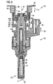
- Figure 2 shows the fuel injector 20 which has a fuel injector body 21 and is suitable for injecting fuel into a combustion chamber of the internal combustion engine 22.
- the fuel injector 20 has a fuel inlet portion 24 and a fuel outlet portion 25.
- the fuel injector cup 30 has a central longitudinal axis L.
- the fuel injector 20 comprises a valve needle 26 taken in a cavity 29 of the fuel injector body 21.
- an injection nozzle 28 is formed which is closed or opened by an axial movement of the valve needle 26. In a closing position a fuel flow through the injection nozzle 28 is prevented. In an opening position fuel can flow through the injection nozzle 28 into the combustion chamber of the internal combustion engine 22.
- the fuel injector 20 has a groove 27 and the fuel injector cup 30 has a groove 32.
- a first snap ring 40 is arranged in the groove 32 of the fuel injector cup 30 and a second snap ring 42 which is arranged in the groove 27 of the fuel injector 20.
- a first flange 36 is in engagement with the first snap ring 40 and a second flange 38 is in engagement with the second snap ring 42.
- the first snap ring 40 enables a positive fitting coupling between the first flange 36 and the fuel injector cup 30 to prevent a movement of the first flange 36 relative to the fuel injector cup 30 in a first direction D1. Therefore, the first flange 36 is fixedly coupled to the fuel injector cup 30.
- the second snap ring 42 enables a positive fitting coupling between the second flange 38 and the fuel injector 20 to prevent a movement of the second flange 38 relative to the fuel injector 20 in a second direction D2. Therefore, the second flange 38 is fixedly coupled to the fuel injector 20.
- the first direction D1 and the second direction D2 are opposite directions of the central longitudinal axis L.
- Figures 2 to 5 show different embodiments of a coupling device 50 which is coupled to the fuel rail 18 of the internal combustion engine 22.
- the coupling device 50 comprises the fuel injector cup 30, the first flange 36, the second flange 38, two shell elements 44, 45 and a fixing element 54.
- the number of shell elements can be one or greater than two.
- the fuel injector cup 30 comprises an inner surface 34 and an outer surface 35 and is hydraulically coupled to the fuel rail 18. Furthermore, the fuel injector cup 30 is in engagement with the fuel inlet portion 24 of the fuel injector 20.
- the fuel inlet portion 24 of the fuel injector 20 comprises a sealing ring 48 with an outer surface 49.
- the first flange 36 is preferably in one part with the fuel injector cup 30 and the second ring 38 is preferably in one part with the fuel injector 20.
- the shell elements 44, 45 have substantially the form of half hollow cylinders. They are arranged in a way that together they are forming basically a cylinder ( figure 4 ). At a first axial end the shell element 44 has a first projection 44a. At a second axial end the shell element 44 has a second projection 44b. The shell element 45 has respective projections 45a, 45b at opposing axial ends. The projections 44a, 44b, 45a, 45b have planar surfaces which are facing the flanges 36, 38. The shell elements 44, 45 have circumferential outer surfaces 52.
- the first flange 36 and the second flange 38 are axially arranged between the first projections 44a, 45a and the second projections 44b, 45b. Consequently, the first flange 36 and the second flange 38 are in engagement with the shell elements 44, 45 to prevent a movement of the flanges 36, 38 in direction of the central longitudinal axis L.
- the fuel injector 20 is fixedly coupled to the fuel injector cup 30 in direction of the central longitudinal axis L.
- the fixing element 54 has a tubular shape and is arranged on the circumferential outer surfaces 52 of the shell elements 44, 45.
- the fixing element 54 has at least one radially spring-loaded element 46 with a spring 46a.
- the spring 46a is a compression spring.
- the spring-loaded element 46 has a spherical shape and is in engagement with a recess 47 in the shell element 44, 45. By this an axial movement of the fixing element 54 relative to the shell element 44, 45 may be prevented.
- the fixing element 54 comprises a plurality of spring-loaded elements 46. This may prevent an axial movement of the fixing element 54 relative to the shell element 44, 45 in a very secure manner.
- the spring-loaded elements 46 are distributed regularly at an inner surface of the fixing element 54, i.e. the spring-loaded elements 46 are distributed with equal angle distances to each other. This may prevent an axial movement of the fixing element 54 relative to the shell element 44, 45 in a very secure manner.
- the fixing element 54 can couple the shell elements 44, 45 fixedly to the flanges 36, 38. Thereby a movement of the shell elements 44, 45 relative to the flanges 36, 38 in a radial direction can be prevented.
- the second flange 38 is fixedly coupled to the fuel injector 20 and the first flange 36 is fixedly coupled to the second flange 38 by the shell elements 44, 45 and the fixing element 54, the fuel injector 20 is retained in the fuel injector cup 30 in direction of the central longitudinal axis L.
- the fuel inlet portion 24 of the fuel injector 20 is shifted into the fuel injector cup 30 in a way that the flanges 36, 38 are in engagement with each other.
- the shell elements 44, 45 are shifted over the flanges 36, 38 in radial direction towards the central longitudinal axis L and the fixing element 54 is shifted over the shell elements 44, 45 in radial direction until the spring-loaded element 46 is in engagement with the recess 47.
- a state as shown in figure 3 is obtained and the shell elements 44, 45 are fixed against a movement in radial direction relative to the flanges 36, 38.
- the inner surface 34 of the fuel injector cup 30 is in sealing engagement with the outer surface 49 of the sealing ring 48. After the assembly process fuel can flow through the fuel injector cup 30 into the fuel inlet portion 24 of the fuel injector 20 without fuel leakage.
- the fixing element 54 is removed from the shell elements 44, 45 and the shell elements 44, 45 are removed from the flanges 36, 38. Then, the fuel injector 20 can be shifted away from the fuel injector cup 30 in axial direction and the fuel injector cup 30 and the fuel injector 20 can be separated from each other.
- the coupling device 50 comprises a ring element 56 which is arranged in axial direction relative and adjacent to the fixing element 54.
- the ring element 56 is in mechanical cooperation with the fuel injector cup 30 and may prevent an axial movement of the fixing element 54 relative to the shell elements 44, 45.
- the ring element 56 is of a rubber or a plastic or comprises a rubber or a plastic.
- the ring element 56 is elastically expandable in radial direction. Therefore, the ring element 56 can be easily disassembled from or assembled to the fuel injector cup 30 and the shell elements 44, 45 during the assembly and disassembly of the fuel injector 20 and the fuel injector cup 30.
- the coupling of the fuel injector 20 with the fuel rail 18 by the flanges 36, 38 and the shell elements 44, 45 allows an assembly of the fuel injector 20 and the fuel injector cup 30 without a further metallic contact between the fuel injector 20 and the further parts of the combustion engine 22.
- a sealing between the fuel injector body 21 and a combustion chamber of the combustion engine 22 can be carried out by a plastic element, in particular by a PTFE element. Consequently, noise transmission between the fuel injector 20 and further parts of the internal combustion engine can be kept small. Furthermore, a proper alignment between the fuel rail 18 and the fuel injector 20 is possible without any particular adjustment.
Description
- The invention relates to a coupling device for hydraulically and mechanically coupling a fuel injector to a fuel rail of a combustion engine.
- Coupling devices for hydraulically and mechanically coupling a fuel injector to a fuel rail are in widespread use, in particular for internal combustion engines. Fuel can be supplied to an internal combustion engine by the fuel rail assembly through the fuel injector. The fuel injectors can be coupled to the fuel injector cups in different manners.
- In order to keep pressure fluctuations during the operation of the internal combustion engine at a very low level, internal combustion engines are supplied with a fuel accumulator to which the fuel injectors are connected and which has a relatively large volume. Such a fuel accumulator is often referred to as a common rail.
- Known fuel rails comprise a hollow body with recesses in form of fuel injector cups, wherein the fuel injectors are arranged. The connection of the fuel injectors to the fuel injector cups that supply the fuel from a fuel tank via a low or high-pressure fuel pump needs to be very precise to get a correct injection angle and a sealing of the fuel.
-
EP 2093414 A1 describes a coupling device for hydraulically and mechanically coupling a fuel injector to a fuel rail of a combustion engine. - The object of the invention is to create a coupling device for hydraulically and mechanically coupling a fuel injector to a fuel rail which is simply to be manufactured and which facilitates a reliable and precise connection between the fuel injector and the fuel injector cup without a resting of the fuel injector on the cylinder head.
- The objects are achieved by the features of the independent claim. Advantageous embodiments of the invention are given in the sub-claims.
- The invention is distinguished by a coupling device for hydraulically and mechanically coupling a fuel injector to a fuel rail of a combustion engine. The coupling device comprises a fuel injector cup having a central longitudinal axis and being designed to be hydraulically coupled to the fuel rail and to engage a fuel inlet portion of the fuel injector. The coupling device comprises a first flange being fixedly coupled to the fuel injector cup and a second flange being fixedly coupled to the fuel injector. The coupling device further comprises at least one shell element. The shell element comprises a first projection and a second projection. The flanges are axially arranged between the first projection and the second projection. The shell element is designed and arranged in a way that the flanges are in mechanical cooperation with the shell element to retain the fuel injector in the fuel injector cup in direction of the central longitudinal axis. The coupling device further comprises a fixing element which is arranged on a circumferential outer surface of the shell element and is designed to prevent a radial movement of the shell element relative to the flanges. A ring element is arranged in axial direction adjacent to the fixing element. The ring element is in mechanical cooperation with the fuel injector cup and/or the shell element and is designed to prevent an axial movement of the fixing element relative to the shell element.
- This has the advantage that a fast and secure coupling of the fuel injector in the fuel injector cup is possible. The coupling device can resist the high fuel pressures in the fuel injector and the fuel injector cup. Furthermore, the coupling of the fuel injector with the fuel rail by the flanges of the fuel injector and the fuel injector cup allows an assembly of the fuel injector and the fuel rail without a further metallic contact between the fuel injector and further parts of the combustion engine. Consequently, a noise transmission between the fuel injector and further parts of the combustion engine can be kept small. The fixing element can ensure a secure coupling between the flanges and the shell elements. The ring element enables a secure arrangement of the fixing element relative to the shell element to prevent a decoupling of the fixing element from the shell element. Furthermore, no particular adjustment is required to obtain a proper alignment between the fuel rail and the fuel injector.
- Further, the invention is distinguished in that the ring element is designed to enable an elastic expansion of the ring element in radial direction. This has the advantage that the ring element can be easily removed from the fuel injector cup for a simple mounting and demounting of the fuel injector to or from the fuel injector cup.
- In a further advantageous embodiment according to the invention the coupling device comprises at least two shell elements. By this, a simple mounting and demounting of the shell elements to or from the flanges is possible. Consequently, a simple mounting and demounting of the fuel injector to or from the fuel injector cup can be carried out. Furthermore, an axial symmetric arrangement of the shell elements is possible. Consequently, an axially symmetrical distribution of forces in the coupling device is possible.
- In a further advantageous embodiment according to the invention the projection forms a shoulder being in mechanical cooperation with the fixing element to prevent a movement of the fixing element relative to the shell element at least in one axial direction.
- In a further advantageous embodiment according to the invention the fixing element has a tubular shape. By this, the fixing element can be easily arranged on the surface of the shell element. Furthermore, the fixing element can enable a secure coupling between the flanges and the shell elements.
- In a further advantageous embodiment according to the invention the fuel injector cup comprises a groove, and a first snap ring is arranged in the groove and is designed to fixedly couple the first flange to the fuel injector cup. The groove and the first snap ring are arranged and designed to form a positive fitting coupling between the first flange and the fuel injector cup which is designed to prevent a movement of the first flange relative to the fuel injector cup at least in a first direction of the central longitudinal axis. This may allow a simple construction of the coupling device which enables to carry out a fast and secure but reversible coupling of the first flange to the fuel injector cup.
- In a further advantageous embodiment according to the invention the first flange is in one part with the fuel injector cup. This has the advantage that a very secure coupling of the fuel injector to the fuel injector cup is possible. Furthermore, a simple machining of the first flange together with the fuel injector cup is possible.
- In a further advantageous embodiment according to the invention the fuel injector comprises a groove, a second snap ring is arranged in the groove of the fuel injector and is designed to fixedly couple the second flange to the fuel injector. The groove of the fuel injector and the second snap ring are arranged and designed to form a positive fitting coupling between the second flange and the fuel injector which is designed to prevent a movement of the second flange relative to the fuel injector at least in a second direction of the central longitudinal axis contrary to the first direction of the central longitudinal. This may allow a simple construction of the coupling device which enables to carry out a fast and secure but reversible coupling of the second flange to the fuel injector.
- In a further advantageous embodiment according to the invention the second flange is in one part with the fuel injector. This has the advantage that a very secure coupling of the fuel injector to the fuel injector cup is possible. Furthermore, a simple machining of the second flange together with the fuel injector is possible.
- Exemplary embodiments of the invention are explained in the following with the aid of schematic drawings. These are as follows:
- Figure 1
- an internal combustion engine in a schematic view,
- Figure 2
- a longitudinal section through a fuel injector,
- Figure 3
- a longitudinal section through one embodiment of a coupling device not comprising the invention,
- Figure 4
- a further embodiment of the coupling device in a perspective view, and
- Figure 5
- a longitudinal section through an embodiment of the coupling device according to the invention.
- Elements of the same design and function that occur in different illustrations are identified by the same reference character.
- A
fuel feed device 10 is assigned to an internal combustion engine 22 (figure 1 ) which can be a diesel engine or a gasoline engine. It includes afuel tank 12 that is connected via a first fuel line to afuel pump 14. The output of thefuel pump 14 is connected to afuel inlet 16 of afuel rail 18. In thefuel rail 18, the fuel is stored for example under a pressure of about 200 bar in the case of a gasoline engine or of about 2,000 bar in the case of a diesel engine.Fuel injectors 20 are connected to thefuel rail 18 by fuel injector cups 30 and the fuel is fed to thefuel injectors 20 via thefuel rail 18. -
Figure 2 shows thefuel injector 20 which has afuel injector body 21 and is suitable for injecting fuel into a combustion chamber of theinternal combustion engine 22. Thefuel injector 20 has afuel inlet portion 24 and afuel outlet portion 25. Thefuel injector cup 30 has a central longitudinal axis L. - Furthermore, the
fuel injector 20 comprises avalve needle 26 taken in acavity 29 of thefuel injector body 21. On a free end of thefuel injector 20 aninjection nozzle 28 is formed which is closed or opened by an axial movement of thevalve needle 26. In a closing position a fuel flow through theinjection nozzle 28 is prevented. In an opening position fuel can flow through theinjection nozzle 28 into the combustion chamber of theinternal combustion engine 22. - The
fuel injector 20 has agroove 27 and thefuel injector cup 30 has agroove 32. Afirst snap ring 40 is arranged in thegroove 32 of thefuel injector cup 30 and asecond snap ring 42 which is arranged in thegroove 27 of thefuel injector 20. Afirst flange 36 is in engagement with thefirst snap ring 40 and asecond flange 38 is in engagement with thesecond snap ring 42. - The
first snap ring 40 enables a positive fitting coupling between thefirst flange 36 and thefuel injector cup 30 to prevent a movement of thefirst flange 36 relative to thefuel injector cup 30 in a first direction D1. Therefore, thefirst flange 36 is fixedly coupled to thefuel injector cup 30. Thesecond snap ring 42 enables a positive fitting coupling between thesecond flange 38 and thefuel injector 20 to prevent a movement of thesecond flange 38 relative to thefuel injector 20 in a second direction D2. Therefore, thesecond flange 38 is fixedly coupled to thefuel injector 20. The first direction D1 and the second direction D2 are opposite directions of the central longitudinal axis L. -
Figures 2 to 5 show different embodiments of acoupling device 50 which is coupled to thefuel rail 18 of theinternal combustion engine 22. - The
coupling device 50 comprises thefuel injector cup 30, thefirst flange 36, thesecond flange 38, twoshell elements element 54. In further embodiments the number of shell elements can be one or greater than two. - The
fuel injector cup 30 comprises aninner surface 34 and anouter surface 35 and is hydraulically coupled to thefuel rail 18. Furthermore, thefuel injector cup 30 is in engagement with thefuel inlet portion 24 of thefuel injector 20. Thefuel inlet portion 24 of thefuel injector 20 comprises a sealingring 48 with anouter surface 49. - As shown in the embodiments of
Figures 3 and5 , thefirst flange 36 is preferably in one part with thefuel injector cup 30 and thesecond ring 38 is preferably in one part with thefuel injector 20. By this a very rigid and very secure coupling between thefuel injector cup 30 and thefuel injector 20 is possible. - The
shell elements figure 4 ). At a first axial end theshell element 44 has afirst projection 44a. At a second axial end theshell element 44 has asecond projection 44b. Theshell element 45 hasrespective projections projections flanges shell elements - The
first flange 36 and thesecond flange 38 are axially arranged between thefirst projections second projections first flange 36 and thesecond flange 38 are in engagement with theshell elements flanges fuel injector 20 is fixedly coupled to thefuel injector cup 30 in direction of the central longitudinal axis L. - Preferably, the fixing
element 54 has a tubular shape and is arranged on the circumferentialouter surfaces 52 of theshell elements - As shown in
Figure 3 , the fixingelement 54 has at least one radially spring-loadedelement 46 with aspring 46a. Preferably, thespring 46a is a compression spring. Preferably, the spring-loadedelement 46 has a spherical shape and is in engagement with arecess 47 in theshell element element 54 relative to theshell element element 54 comprises a plurality of spring-loadedelements 46. This may prevent an axial movement of the fixingelement 54 relative to theshell element elements 46 are distributed regularly at an inner surface of the fixingelement 54, i.e. the spring-loadedelements 46 are distributed with equal angle distances to each other. This may prevent an axial movement of the fixingelement 54 relative to theshell element - The fixing
element 54 can couple theshell elements flanges shell elements flanges - As the
first flange 36 is fixedly coupled to thefuel injector cup 30, thesecond flange 38 is fixedly coupled to thefuel injector 20 and thefirst flange 36 is fixedly coupled to thesecond flange 38 by theshell elements element 54, thefuel injector 20 is retained in thefuel injector cup 30 in direction of the central longitudinal axis L. - In the following, the assembly and disassembly of the
fuel injector 20 and thefuel injector cup 30 according to the embodiment offigures 3 and 4 will be described: - For assembling, the
fuel inlet portion 24 of thefuel injector 20 is shifted into thefuel injector cup 30 in a way that theflanges shell elements flanges element 54 is shifted over theshell elements element 46 is in engagement with therecess 47. Now, a state as shown infigure 3 is obtained and theshell elements flanges figure 3 , theinner surface 34 of thefuel injector cup 30 is in sealing engagement with theouter surface 49 of the sealingring 48. After the assembly process fuel can flow through thefuel injector cup 30 into thefuel inlet portion 24 of thefuel injector 20 without fuel leakage. - To disassemble the
fuel injector 20 from thefuel injector cup 30, the fixingelement 54 is removed from theshell elements shell elements flanges fuel injector 20 can be shifted away from thefuel injector cup 30 in axial direction and thefuel injector cup 30 and thefuel injector 20 can be separated from each other. - As shown in
Figure 5 , thecoupling device 50 comprises aring element 56 which is arranged in axial direction relative and adjacent to the fixingelement 54. Thering element 56 is in mechanical cooperation with thefuel injector cup 30 and may prevent an axial movement of the fixingelement 54 relative to theshell elements ring element 56 is of a rubber or a plastic or comprises a rubber or a plastic. Thering element 56 is elastically expandable in radial direction. Therefore, thering element 56 can be easily disassembled from or assembled to thefuel injector cup 30 and theshell elements fuel injector 20 and thefuel injector cup 30. - The coupling of the
fuel injector 20 with thefuel rail 18 by theflanges shell elements fuel injector 20 and thefuel injector cup 30 without a further metallic contact between thefuel injector 20 and the further parts of thecombustion engine 22. A sealing between thefuel injector body 21 and a combustion chamber of thecombustion engine 22 can be carried out by a plastic element, in particular by a PTFE element. Consequently, noise transmission between thefuel injector 20 and further parts of the internal combustion engine can be kept small. Furthermore, a proper alignment between thefuel rail 18 and thefuel injector 20 is possible without any particular adjustment.
Claims (8)
- Coupling device (50) for hydraulically and mechanically coupling a fuel injector (20) to a fuel rail (14) of a combustion engine (22), the coupling device (50) comprising- a fuel injector cup (30) having a central longitudinal axis (L) and being designed to be hydraulically coupled to the fuel rail (14) and to engage a fuel inlet portion (24) of the fuel injector (20),- a first flange (36) being fixedly coupled to the fuel injector cup (30) and a second flange (38) being fixedly coupled to the fuel injector (20),- at least one shell element (44, 45), the shell element (44, 45) comprising a first projection (44a, 45a) and a second projection (44b, 45b), the flanges (36, 38) being axially arranged between the first projection (44a, 45a) and the second projection (44b, 45b), and the shell element (44, 45) being designed and arranged in a way that the flanges (36, 38) are in mechanical cooperation with the shell element (44, 45) to retain the fuel injector (20) in the fuel injector cup (30) in direction of the central longitudinal axis (L), and- a fixing element (54) being arranged on a circumferential outer surface (52) of the shell element (44, 45) and being designed to prevent a radial movement of the shell element (44, 45) relative to the flanges (36, 38), whereina ring element (56) is arranged in axial direction adjacent to the fixing element (54), the ring element (56) being in mechanical cooperation with the fuel injector cup (30) and/or the shell element (44, 45), being designed to prevent an axial movement of the fixing element (54) relative to the shell element (44, 45),
and being designed to enable an elastic expansion of the ring element (56) in radial direction. - Coupling device (50) in accordance with claim 1, comprising at least two shell elements (44, 45).
- Coupling device (50) in accordance with one of the preceding claims, wherein the projection (44, 45) forms a shoulder being in mechanical cooperation with the fixing element (54) to prevent a movement of the fixing element (54) relative to the shell element (44, 45) at least in one axial direction (D1, D2).
- Coupling device (50) in accordance with one of the preceding claims, with the fixing element (54) having a tubular shape.
- Coupling device (50) in accordance with one of the preceding claims, with the fuel injector cup (30) comprising a groove (32), a first snap ring (40) being arranged in the groove (32), with the groove (32) and the first snap ring (40) being arranged and designed to form a positive fitting coupling between the first flange (36) and the fuel injector cup (30) which is designed to prevent a movement of the first flange (36) relative to the fuel injector cup (30) at least in a first direction (D1) of the central longitudinal axis (L).
- Coupling device (50) in accordance with one of the claims 1 to 4, with the first flange (36) being in one part with the fuel injector cup (30).
- Coupling device (50) in accordance with one of the preceding claims, with the fuel injector (20) comprising a groove (27), a second snap ring (42) being arranged in the groove (27) of the fuel injector (20), with the groove (27) of the fuel injector (20) and the second snap ring (42) being arranged and designed to form a positive fitting coupling between the second flange (38) and the fuel injector (20) which is designed to prevent a movement of the second flange (38) relative to the fuel injector (20) at least in a second direction (D2) of the central longitudinal axis (L) contrary to the first direction (D1) of the central longitudinal axis (L).
- Coupling device (50) in accordance with one of the claims 1 to 6, with the second flange (38) being in one part with the fuel injector (20).
Priority Applications (2)
| Application Number | Priority Date | Filing Date | Title |
|---|---|---|---|
| EP09009637.1A EP2292920B1 (en) | 2009-07-24 | 2009-07-24 | Coupling device |
| US12/843,040 US8511280B2 (en) | 2009-07-24 | 2010-07-25 | Coupling device |
Applications Claiming Priority (1)
| Application Number | Priority Date | Filing Date | Title |
|---|---|---|---|
| EP09009637.1A EP2292920B1 (en) | 2009-07-24 | 2009-07-24 | Coupling device |
Publications (2)
| Publication Number | Publication Date |
|---|---|
| EP2292920A1 EP2292920A1 (en) | 2011-03-09 |
| EP2292920B1 true EP2292920B1 (en) | 2013-09-11 |
Family
ID=41403085
Family Applications (1)
| Application Number | Title | Priority Date | Filing Date |
|---|---|---|---|
| EP09009637.1A Not-in-force EP2292920B1 (en) | 2009-07-24 | 2009-07-24 | Coupling device |
Country Status (2)
| Country | Link |
|---|---|
| US (1) | US8511280B2 (en) |
| EP (1) | EP2292920B1 (en) |
Families Citing this family (3)
| Publication number | Priority date | Publication date | Assignee | Title |
|---|---|---|---|---|
| DE102012206890A1 (en) * | 2012-04-26 | 2013-10-31 | Robert Bosch Gmbh | Arrangement with a fuel distributor and a plurality of fuel injection valves |
| EP2813699B1 (en) * | 2013-06-14 | 2018-09-05 | FPT Motorenforschung AG | Fuel piping arrangement in common rail type fuel supply systems |
| EP2824312B1 (en) | 2013-07-10 | 2017-06-28 | Continental Automotive GmbH | Fuel injection assembly for a combustion engine |
Family Cites Families (11)
| Publication number | Priority date | Publication date | Assignee | Title |
|---|---|---|---|---|
| US2438626A (en) * | 1946-06-07 | 1948-03-30 | Geometric Tool Company | Collapsing tap |
| SE361201B (en) * | 1966-06-03 | 1973-10-22 | Stenberg Flygt Ab | |
| DE19735665A1 (en) * | 1997-06-25 | 1999-01-07 | Bosch Gmbh Robert | Fuel injection system |
| US6053149A (en) * | 1998-05-28 | 2000-04-25 | Siemens Automotive Corporation | Fuel injector clip retention arrangement |
| US6481420B2 (en) * | 2001-01-30 | 2002-11-19 | Visteon Global Technologies, Inc. | Method and apparatus for maintaining the alignment of a fuel injector |
| DE10108203A1 (en) * | 2001-02-21 | 2002-08-29 | Bosch Gmbh Robert | Mounting bracket and method for mounting a fuel injector |
| JP4634765B2 (en) * | 2004-09-16 | 2011-02-16 | 日産自動車株式会社 | Fuel injection valve mounting structure |
| EP1849995B1 (en) * | 2006-04-24 | 2011-08-10 | Continental Automotive GmbH | Coupling arrangement for mounting an injector in a fuel rail |
| DE602006005796D1 (en) * | 2006-06-01 | 2009-04-30 | Continental Automotive Gmbh | Connector and composite arrangement |
| JP4558021B2 (en) * | 2007-09-06 | 2010-10-06 | 日立オートモティブシステムズ株式会社 | Fuel injection valve and method for supporting the same |
| EP2093414B1 (en) * | 2008-02-19 | 2011-07-20 | Continental Automotive GmbH | Coupling device |
-
2009
- 2009-07-24 EP EP09009637.1A patent/EP2292920B1/en not_active Not-in-force
-
2010
- 2010-07-25 US US12/843,040 patent/US8511280B2/en not_active Expired - Fee Related
Also Published As
| Publication number | Publication date |
|---|---|
| EP2292920A1 (en) | 2011-03-09 |
| US8511280B2 (en) | 2013-08-20 |
| US20110017175A1 (en) | 2011-01-27 |
Similar Documents
| Publication | Publication Date | Title |
|---|---|---|
| EP2103804B1 (en) | Coupling arrangement | |
| EP2093414B1 (en) | Coupling device | |
| US8286612B2 (en) | Coupling device | |
| US10539105B2 (en) | Fuel injector and fuel injector assembly | |
| EP2093413B1 (en) | Coupling device | |
| EP2375052B1 (en) | Fuel injector assembly | |
| US7942453B2 (en) | Coupling device | |
| US8245697B2 (en) | Coupling device | |
| US7976073B2 (en) | Coupling device | |
| EP2241745B1 (en) | Coupling device | |
| EP2292920B1 (en) | Coupling device | |
| EP2388468B1 (en) | Coupling device | |
| US10018168B2 (en) | Fuel injector and fuel-injection system | |
| EP2090772B1 (en) | Coupling assembly |
Legal Events
| Date | Code | Title | Description |
|---|---|---|---|
| PUAI | Public reference made under article 153(3) epc to a published international application that has entered the european phase |
Free format text: ORIGINAL CODE: 0009012 |
|
| AK | Designated contracting states |
Kind code of ref document: A1 Designated state(s): AT BE BG CH CY CZ DE DK EE ES FI FR GB GR HR HU IE IS IT LI LT LU LV MC MK MT NL NO PL PT RO SE SI SK SM TR |
|
| AX | Request for extension of the european patent |
Extension state: AL BA RS |
|
| 17P | Request for examination filed |
Effective date: 20110909 |
|
| 17Q | First examination report despatched |
Effective date: 20110923 |
|
| GRAP | Despatch of communication of intention to grant a patent |
Free format text: ORIGINAL CODE: EPIDOSNIGR1 |
|
| GRAP | Despatch of communication of intention to grant a patent |
Free format text: ORIGINAL CODE: EPIDOSNIGR1 |
|
| INTG | Intention to grant announced |
Effective date: 20130425 |
|
| GRAS | Grant fee paid |
Free format text: ORIGINAL CODE: EPIDOSNIGR3 |
|
| GRAA | (expected) grant |
Free format text: ORIGINAL CODE: 0009210 |
|
| AK | Designated contracting states |
Kind code of ref document: B1 Designated state(s): AT BE BG CH CY CZ DE DK EE ES FI FR GB GR HR HU IE IS IT LI LT LU LV MC MK MT NL NO PL PT RO SE SI SK SM TR |
|
| REG | Reference to a national code |
Ref country code: GB Ref legal event code: FG4D |
|
| REG | Reference to a national code |
Ref country code: CH Ref legal event code: EP |
|
| REG | Reference to a national code |
Ref country code: AT Ref legal event code: REF Ref document number: 631782 Country of ref document: AT Kind code of ref document: T Effective date: 20130915 |
|
| REG | Reference to a national code |
Ref country code: IE Ref legal event code: FG4D |
|
| REG | Reference to a national code |
Ref country code: DE Ref legal event code: R096 Ref document number: 602009018658 Country of ref document: DE Effective date: 20131107 |
|
| PG25 | Lapsed in a contracting state [announced via postgrant information from national office to epo] |
Ref country code: NO Free format text: LAPSE BECAUSE OF FAILURE TO SUBMIT A TRANSLATION OF THE DESCRIPTION OR TO PAY THE FEE WITHIN THE PRESCRIBED TIME-LIMIT Effective date: 20131211 Ref country code: LT Free format text: LAPSE BECAUSE OF FAILURE TO SUBMIT A TRANSLATION OF THE DESCRIPTION OR TO PAY THE FEE WITHIN THE PRESCRIBED TIME-LIMIT Effective date: 20130911 Ref country code: HR Free format text: LAPSE BECAUSE OF FAILURE TO SUBMIT A TRANSLATION OF THE DESCRIPTION OR TO PAY THE FEE WITHIN THE PRESCRIBED TIME-LIMIT Effective date: 20130911 Ref country code: SE Free format text: LAPSE BECAUSE OF FAILURE TO SUBMIT A TRANSLATION OF THE DESCRIPTION OR TO PAY THE FEE WITHIN THE PRESCRIBED TIME-LIMIT Effective date: 20130911 Ref country code: CY Free format text: LAPSE BECAUSE OF FAILURE TO SUBMIT A TRANSLATION OF THE DESCRIPTION OR TO PAY THE FEE WITHIN THE PRESCRIBED TIME-LIMIT Effective date: 20130710 |
|
| REG | Reference to a national code |
Ref country code: NL Ref legal event code: VDEP Effective date: 20130911 |
|
| REG | Reference to a national code |
Ref country code: AT Ref legal event code: MK05 Ref document number: 631782 Country of ref document: AT Kind code of ref document: T Effective date: 20130911 |
|
| REG | Reference to a national code |
Ref country code: LT Ref legal event code: MG4D |
|
| PG25 | Lapsed in a contracting state [announced via postgrant information from national office to epo] |
Ref country code: SI Free format text: LAPSE BECAUSE OF FAILURE TO SUBMIT A TRANSLATION OF THE DESCRIPTION OR TO PAY THE FEE WITHIN THE PRESCRIBED TIME-LIMIT Effective date: 20130911 Ref country code: LV Free format text: LAPSE BECAUSE OF FAILURE TO SUBMIT A TRANSLATION OF THE DESCRIPTION OR TO PAY THE FEE WITHIN THE PRESCRIBED TIME-LIMIT Effective date: 20130911 Ref country code: FI Free format text: LAPSE BECAUSE OF FAILURE TO SUBMIT A TRANSLATION OF THE DESCRIPTION OR TO PAY THE FEE WITHIN THE PRESCRIBED TIME-LIMIT Effective date: 20130911 |
|
| PG25 | Lapsed in a contracting state [announced via postgrant information from national office to epo] |
Ref country code: BE Free format text: LAPSE BECAUSE OF FAILURE TO SUBMIT A TRANSLATION OF THE DESCRIPTION OR TO PAY THE FEE WITHIN THE PRESCRIBED TIME-LIMIT Effective date: 20130911 Ref country code: CY Free format text: LAPSE BECAUSE OF FAILURE TO SUBMIT A TRANSLATION OF THE DESCRIPTION OR TO PAY THE FEE WITHIN THE PRESCRIBED TIME-LIMIT Effective date: 20130911 |
|
| PG25 | Lapsed in a contracting state [announced via postgrant information from national office to epo] |
Ref country code: CZ Free format text: LAPSE BECAUSE OF FAILURE TO SUBMIT A TRANSLATION OF THE DESCRIPTION OR TO PAY THE FEE WITHIN THE PRESCRIBED TIME-LIMIT Effective date: 20130911 Ref country code: SK Free format text: LAPSE BECAUSE OF FAILURE TO SUBMIT A TRANSLATION OF THE DESCRIPTION OR TO PAY THE FEE WITHIN THE PRESCRIBED TIME-LIMIT Effective date: 20130911 Ref country code: IS Free format text: LAPSE BECAUSE OF FAILURE TO SUBMIT A TRANSLATION OF THE DESCRIPTION OR TO PAY THE FEE WITHIN THE PRESCRIBED TIME-LIMIT Effective date: 20140111 Ref country code: RO Free format text: LAPSE BECAUSE OF FAILURE TO SUBMIT A TRANSLATION OF THE DESCRIPTION OR TO PAY THE FEE WITHIN THE PRESCRIBED TIME-LIMIT Effective date: 20130911 Ref country code: NL Free format text: LAPSE BECAUSE OF FAILURE TO SUBMIT A TRANSLATION OF THE DESCRIPTION OR TO PAY THE FEE WITHIN THE PRESCRIBED TIME-LIMIT Effective date: 20130911 Ref country code: EE Free format text: LAPSE BECAUSE OF FAILURE TO SUBMIT A TRANSLATION OF THE DESCRIPTION OR TO PAY THE FEE WITHIN THE PRESCRIBED TIME-LIMIT Effective date: 20130911 |
|
| PG25 | Lapsed in a contracting state [announced via postgrant information from national office to epo] |
Ref country code: PL Free format text: LAPSE BECAUSE OF FAILURE TO SUBMIT A TRANSLATION OF THE DESCRIPTION OR TO PAY THE FEE WITHIN THE PRESCRIBED TIME-LIMIT Effective date: 20130911 Ref country code: ES Free format text: LAPSE BECAUSE OF FAILURE TO SUBMIT A TRANSLATION OF THE DESCRIPTION OR TO PAY THE FEE WITHIN THE PRESCRIBED TIME-LIMIT Effective date: 20130911 Ref country code: AT Free format text: LAPSE BECAUSE OF FAILURE TO SUBMIT A TRANSLATION OF THE DESCRIPTION OR TO PAY THE FEE WITHIN THE PRESCRIBED TIME-LIMIT Effective date: 20130911 |
|
| REG | Reference to a national code |
Ref country code: DE Ref legal event code: R097 Ref document number: 602009018658 Country of ref document: DE |
|
| PG25 | Lapsed in a contracting state [announced via postgrant information from national office to epo] |
Ref country code: PT Free format text: LAPSE BECAUSE OF FAILURE TO SUBMIT A TRANSLATION OF THE DESCRIPTION OR TO PAY THE FEE WITHIN THE PRESCRIBED TIME-LIMIT Effective date: 20140113 |
|
| PLBE | No opposition filed within time limit |
Free format text: ORIGINAL CODE: 0009261 |
|
| STAA | Information on the status of an ep patent application or granted ep patent |
Free format text: STATUS: NO OPPOSITION FILED WITHIN TIME LIMIT |
|
| 26N | No opposition filed |
Effective date: 20140612 |
|
| REG | Reference to a national code |
Ref country code: DE Ref legal event code: R097 Ref document number: 602009018658 Country of ref document: DE Effective date: 20140612 |
|
| PG25 | Lapsed in a contracting state [announced via postgrant information from national office to epo] |
Ref country code: DK Free format text: LAPSE BECAUSE OF FAILURE TO SUBMIT A TRANSLATION OF THE DESCRIPTION OR TO PAY THE FEE WITHIN THE PRESCRIBED TIME-LIMIT Effective date: 20130911 |
|
| PG25 | Lapsed in a contracting state [announced via postgrant information from national office to epo] |
Ref country code: LU Free format text: LAPSE BECAUSE OF FAILURE TO SUBMIT A TRANSLATION OF THE DESCRIPTION OR TO PAY THE FEE WITHIN THE PRESCRIBED TIME-LIMIT Effective date: 20140724 |
|
| REG | Reference to a national code |
Ref country code: CH Ref legal event code: PL |
|
| GBPC | Gb: european patent ceased through non-payment of renewal fee |
Effective date: 20140724 |
|
| REG | Reference to a national code |
Ref country code: IE Ref legal event code: MM4A |
|
| PG25 | Lapsed in a contracting state [announced via postgrant information from national office to epo] |
Ref country code: CH Free format text: LAPSE BECAUSE OF NON-PAYMENT OF DUE FEES Effective date: 20140731 Ref country code: LI Free format text: LAPSE BECAUSE OF NON-PAYMENT OF DUE FEES Effective date: 20140731 |
|
| PG25 | Lapsed in a contracting state [announced via postgrant information from national office to epo] |
Ref country code: GB Free format text: LAPSE BECAUSE OF NON-PAYMENT OF DUE FEES Effective date: 20140724 |
|
| PG25 | Lapsed in a contracting state [announced via postgrant information from national office to epo] |
Ref country code: IE Free format text: LAPSE BECAUSE OF NON-PAYMENT OF DUE FEES Effective date: 20140724 |
|
| PG25 | Lapsed in a contracting state [announced via postgrant information from national office to epo] |
Ref country code: MC Free format text: LAPSE BECAUSE OF FAILURE TO SUBMIT A TRANSLATION OF THE DESCRIPTION OR TO PAY THE FEE WITHIN THE PRESCRIBED TIME-LIMIT Effective date: 20130911 Ref country code: SM Free format text: LAPSE BECAUSE OF FAILURE TO SUBMIT A TRANSLATION OF THE DESCRIPTION OR TO PAY THE FEE WITHIN THE PRESCRIBED TIME-LIMIT Effective date: 20130911 |
|
| PG25 | Lapsed in a contracting state [announced via postgrant information from national office to epo] |
Ref country code: MT Free format text: LAPSE BECAUSE OF FAILURE TO SUBMIT A TRANSLATION OF THE DESCRIPTION OR TO PAY THE FEE WITHIN THE PRESCRIBED TIME-LIMIT Effective date: 20130911 Ref country code: GR Free format text: LAPSE BECAUSE OF FAILURE TO SUBMIT A TRANSLATION OF THE DESCRIPTION OR TO PAY THE FEE WITHIN THE PRESCRIBED TIME-LIMIT Effective date: 20130911 Ref country code: BG Free format text: LAPSE BECAUSE OF FAILURE TO SUBMIT A TRANSLATION OF THE DESCRIPTION OR TO PAY THE FEE WITHIN THE PRESCRIBED TIME-LIMIT Effective date: 20130911 |
|
| REG | Reference to a national code |
Ref country code: FR Ref legal event code: PLFP Year of fee payment: 8 |
|
| PG25 | Lapsed in a contracting state [announced via postgrant information from national office to epo] |
Ref country code: HU Free format text: LAPSE BECAUSE OF FAILURE TO SUBMIT A TRANSLATION OF THE DESCRIPTION OR TO PAY THE FEE WITHIN THE PRESCRIBED TIME-LIMIT; INVALID AB INITIO Effective date: 20090724 Ref country code: TR Free format text: LAPSE BECAUSE OF FAILURE TO SUBMIT A TRANSLATION OF THE DESCRIPTION OR TO PAY THE FEE WITHIN THE PRESCRIBED TIME-LIMIT Effective date: 20130911 |
|
| REG | Reference to a national code |
Ref country code: FR Ref legal event code: PLFP Year of fee payment: 9 |
|
| PG25 | Lapsed in a contracting state [announced via postgrant information from national office to epo] |
Ref country code: MK Free format text: LAPSE BECAUSE OF FAILURE TO SUBMIT A TRANSLATION OF THE DESCRIPTION OR TO PAY THE FEE WITHIN THE PRESCRIBED TIME-LIMIT Effective date: 20130911 |
|
| REG | Reference to a national code |
Ref country code: FR Ref legal event code: PLFP Year of fee payment: 10 |
|
| PGFP | Annual fee paid to national office [announced via postgrant information from national office to epo] |
Ref country code: DE Payment date: 20180731 Year of fee payment: 10 Ref country code: FR Payment date: 20180725 Year of fee payment: 10 Ref country code: IT Payment date: 20180724 Year of fee payment: 10 |
|
| REG | Reference to a national code |
Ref country code: DE Ref legal event code: R119 Ref document number: 602009018658 Country of ref document: DE |
|
| PG25 | Lapsed in a contracting state [announced via postgrant information from national office to epo] |
Ref country code: DE Free format text: LAPSE BECAUSE OF NON-PAYMENT OF DUE FEES Effective date: 20200201 |
|
| PG25 | Lapsed in a contracting state [announced via postgrant information from national office to epo] |
Ref country code: FR Free format text: LAPSE BECAUSE OF NON-PAYMENT OF DUE FEES Effective date: 20190731 |
|
| PG25 | Lapsed in a contracting state [announced via postgrant information from national office to epo] |
Ref country code: IT Free format text: LAPSE BECAUSE OF NON-PAYMENT OF DUE FEES Effective date: 20190724 |