EP0967437A1 - Improvement to combustion apparatus with several combustion air inlet ducts - Google Patents
Improvement to combustion apparatus with several combustion air inlet ducts Download PDFInfo
- Publication number
- EP0967437A1 EP0967437A1 EP99430011A EP99430011A EP0967437A1 EP 0967437 A1 EP0967437 A1 EP 0967437A1 EP 99430011 A EP99430011 A EP 99430011A EP 99430011 A EP99430011 A EP 99430011A EP 0967437 A1 EP0967437 A1 EP 0967437A1
- Authority
- EP
- European Patent Office
- Prior art keywords
- burner
- register
- registers
- combustion
- burner according
- Prior art date
- Legal status (The legal status is an assumption and is not a legal conclusion. Google has not performed a legal analysis and makes no representation as to the accuracy of the status listed.)
- Granted
Links
Images


Classifications
-
- F—MECHANICAL ENGINEERING; LIGHTING; HEATING; WEAPONS; BLASTING
- F23—COMBUSTION APPARATUS; COMBUSTION PROCESSES
- F23D—BURNERS
- F23D17/00—Burners for combustion conjointly or alternatively of gaseous or liquid or pulverulent fuel
- F23D17/002—Burners for combustion conjointly or alternatively of gaseous or liquid or pulverulent fuel gaseous or liquid fuel
-
- F—MECHANICAL ENGINEERING; LIGHTING; HEATING; WEAPONS; BLASTING
- F23—COMBUSTION APPARATUS; COMBUSTION PROCESSES
- F23C—METHODS OR APPARATUS FOR COMBUSTION USING FLUID FUEL OR SOLID FUEL SUSPENDED IN A CARRIER GAS OR AIR
- F23C7/00—Combustion apparatus characterised by arrangements for air supply
- F23C7/008—Flow control devices
-
- F—MECHANICAL ENGINEERING; LIGHTING; HEATING; WEAPONS; BLASTING
- F23—COMBUSTION APPARATUS; COMBUSTION PROCESSES
- F23L—SUPPLYING AIR OR NON-COMBUSTIBLE LIQUIDS OR GASES TO COMBUSTION APPARATUS IN GENERAL ; VALVES OR DAMPERS SPECIALLY ADAPTED FOR CONTROLLING AIR SUPPLY OR DRAUGHT IN COMBUSTION APPARATUS; INDUCING DRAUGHT IN COMBUSTION APPARATUS; TOPS FOR CHIMNEYS OR VENTILATING SHAFTS; TERMINALS FOR FLUES
- F23L13/00—Construction of valves or dampers for controlling air supply or draught
Definitions
- the present invention relates to an improvement made to combustion appliances comprising several transport conduits oxidizer.
- the technical sector of the invention is the field of manufacture of burner combustion appliances, such as boilers, hot gas generators, ovens or others.
- the present invention applies to combustion appliances using one or more solid and / or powdery fuels, or well fluids, which comprise at least one burner associated with at least two coaxial ducts for transporting gaseous oxidant.
- the present invention applies in particular to installations of cogeneration of electrical and thermal energy in which exhaust gases from engines or turbines are heated by one or several burners, being used as oxidizer, then are used to produce steam, hot water or hot gases.
- the object of the present invention is to propose a system improved adjustment of the oxidizer flow rate delivered to the burners; the present invention applies to burners equipped with several circuits or oxidizer conduits; in such installations, a conduit central conveys an oxidizer current generally called primary, which surrounds and extends coaxially with the nose of the burner; one or several other annular section conduits extend around the central duct and carry a flow or stream of oxidant said secondary and where appropriate tertiary.
- patent N ° FR 2,188,780 (Pillard) describes a sliding damper in which an external ferrule movable relative to a fixed internal ferrule is supported by pivots mounted on Watt parallelograms, ensuring movement (sliding) without no contact or friction; it has also been found in practice that this device does not allow stable and precise regulation of the air flow rate passing through the damper, these registers being used in practice ("all or nothing") to close completely or to open totally an air passage.
- the object of the present invention is to provide a burner and a combustion appliance fitted with an improved flow control system oxidizer.
- the invention consists in proposing a burner associated with at least two ducts for transporting gaseous oxidant, which comprises at at least two sliding cylindrical registers, to allow adjustment independent of the respective oxidizer flow admitted through openings annular and / or arranged annularly in each of said conduits transport of oxidizer;
- the burner has a central duct supply of primary oxidant (air), inside which coaxially extend a completed fuel injection pipe by one or more nozzles and a stabilizer comprising a hub forming a screen surrounding the rod, which is set back from the nozzles and is provided with peripheral fins, the burner further comprising a secondary oxidant (air) supply line extending around from the central duct;
- each register is supported by a structure articulated comprising at least two or three parallelograms of Watt.
- the burner according to the invention ensures combustion stable and low pollution for very operating conditions variable and allows full use of flame stability resulting from the stabilization device described in the patent N ° FR 2.122.820, which allows the creation of a fiery toric eddy at the birth of the flame and around it, improving the attachment, ignition and quality of the flame.
- said cylindrical registers are coaxial, sliding mounted along their common longitudinal axis, and are of substantially identical diameter.
- the flow adjustment oxidant circulating and / or admitted into the conduits can, on the one hand be carried out independently for each conduit in order to maintain oxidizer injection rates into the combustion chamber at predetermined values, and can on the other hand be performed more specifically, over a larger range of flow variation, and with variable oxidizer supply pressures.
- the idea behind the invention is therefore to use a register with Watt parallelogram for each of the circuits of a fitted burner two separate air circuits, for example to obtain a reduction nitrogen oxide emissions by air staging, or to use turbine gases or ambient air in cogeneration.
- a further improvement is to use these registers to adjust the flow rates in each circuit, regulating the position partial opening taking advantage of the fact that the parallelogram of Watt, without friction and without play, allows a precise and faithful adjustment. This adjustment is facilitated by having a grid at the openings perforated or grooved improving the progressiveness of the opening of the passage section.
- Optimal performance in terms of stability and precision adjustment of partial opening of the damper, are obtained by providing a deformable seal ensuring contact between the fixed shell and the movable ferrule in any position of the register; this joint preferably takes the form of a metal broom annular which is engaged in an annular groove of the movable shell, which stiffens it.
- the compactness of the assembly can in particular be optimized by providing for a crossing (or overlapping or overlapping) of registers and / or their support, guiding and translational drive, for certain open positions; this recovery can take place in the open position of two registers whose directions of opening movements are opposite.
- the compactness of the assembly combining two or three registers is particularly optimized by providing registers whose diameters are such that the ratio of the diameter of the external register to the diameter of the internal register is less than or equal to 2 (and greater than 1 except in certain cases where the diameters are substantially identical), in particular of the order of 1.3 to 1.6.
- diameter is meant the equivalent diameters of the profile cross section of the register, in case the cross section of oxidizer ducts and their associated registers is not in shape circular, but for example square or rectangular.
- Another advantage provided by the invention is that it allows, in a combustion appliance equipped with two (at least) powered burners by combustion by a single duct, to regulate easily, precisely and stably, usually at the same value if it is identical burners, the oxidizer flow delivered to each each burner, and therefore makes it possible to resolve the difficulties inherent in such balancing of oxidizer flows regulated by registers arranged in parallel.
- Each register can be fitted with sealing means prohibiting the passage of oxidizer in the closed position (and / or limiting as much as possible the "leakage" rate in this position); these sealing means may include a linked crown or flange (or fixed or integrated) at one longitudinal end of the damper; this crown is able to come into contact with (or press on) fixed crown (or flange) forming part of the structure of the device, in closing position of the register; a metal joint may have or be constituted by said flat crown fixed to the register and extending in a transverse plane (with reference to the longitudinal axis of symmetry of the register); by making this crown in a sheet of thin, in particular of the order of 0.5 to 2 millimeters, this crown may deform slightly when pressed on the fixed crown of the structure, which ensures contact with the other end of the register, along its entire perimeter, with a second wall or crown fixed device, which therefore ensures closure substantially sealed from the register by circumferential contact of its two longitudinal ends with the fixed structure of the device combustion.
- the structure of the cylindrical damper consists of a thin sheet, in particular of 1 to 3 millimeters, rolled and welded to form a ferrule cylindrical of circular section, which is provided with one or more annular or circumferential reinforcements (or stiffeners), which stiffen the structure of the register, which allows to obtain a light register of simple construction; this reinforcement can be obtained (or constituted) by a fold or circumferential undulation made in the sheet metal of the register.
- This structure of multiple sliding registers is particularly suitable for outlet gas heating installations of gas engines or turbines, in cogeneration plants.
- the gases escaping from the heater are heated engine or turbine by causing them to burn; in times of engine or turbine operation, these oxidizing gases are delivered in large quantities to burners at a temperature of the order of 500 ° C; when the engine or turbine stops, the burner is supplied with cold air, in much smaller quantity; the system according the invention allows in this operating mode, by closing of one of the registers, to adapt to these variations in operation.
- This device is also suitable for air stage burners in which a first part of the combustion air is injected into the center of the burner, and the other part is injected by nozzles or by a annular space coaxial with the burner, on a diameter of the order of 1.2 to 2 times the diameter of the internal circuit; these burners are intended for reduce nitrogen oxide emissions.
- each of the sliding cylindrical registers are constituted by an articulated structure comprising two or three Watt parallelograms, which is preferably actuated by a jack associated with each register, under the control of a control unit, and extends outside and around the movable cylindrical wall of each register; alternatively, this structure is actuated manually.
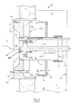
- Figure 1 illustrates in partial cross-sectional view a combustion appliance equipped with a burner associated with two transport of oxidizer, each equipped with a sliding damper cylindrical.
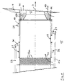
- Figure 2 is a simplified perspective view of the register of figure 1.
- Figure 3 illustrates in cross-sectional (and longitudinal) view simplified the application of the invention to a burner associated with means of combustion smoke recirculation.
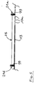
- Figure 4 illustrates in partial longitudinal section view a burner equipped with two registers of the same diameter
- Figure 5 is a partial enlarged view of Figure 4 illustrating the movable shell of a damper fitted with sealing brushes at each end.
- the apparatus 1 to combustion allows the production of a flame 2 in a combustion 3 delimited by walls 4 of refractory material.
- This burner is associated with a duct 8, extending along the axis longitudinal 7 of symmetry, transporting a fuel (liquid or pulverulent) up to the burner nose, as well as conduits 9 delivering gas (such as natural gas or LPG by example).
- a fuel liquid or pulverulent
- conduits 9 delivering gas (such as natural gas or LPG by example).
- the wall 4 has a second annular orifice 10 which defines a conduit 11 for transporting oxidant gas through the wall 4.
- a fixed structure consisting of a cylindrical shell 13 of axis 7 and a flange 14 essentially, delimits a central duct 12 serving also to the delivery of oxidizer to the nose 6a of the burner 6.
- the apparatus 1 has a chamber 15 separate from the chamber 3 by the wall 4, and in which the conduits 8, 9 and a part extend of the structure 14, 13 of the burner, in which chamber 15 are admitted the gases (or the air serving as oxidizer) which are delivered by a conduit 16, according to a radial flow represented by arrow 17.
- the device shown in Figures 1 to 3 includes a sliding register internal cylindrical 21, which is shown in the open position maximum in FIG. 1 and in the intermediate position in FIG. 3, and an external cylindrical sliding damper 19 shown in the position of closure in Figures 1 and 3; register 21 allows passage according to the arrow 20 of the oxidizing gases in the central channel 12 for transporting oxidizer to the burner nose, while register 19 prohibits the circulation 18 of oxidizer towards the second conduit or channel 11 of transport of the oxidant to the combustion chamber 3, in the position shown in Figures 1 and 3.
- the register 21 mounted sliding along the axis 7, like the register 19, is in the form of a cylindrical shell of circular section, of which the end 21a can come by sliding, with a view to closing the passage 33, in contact with a wall 23 delimiting the chamber 15 and at through which lines 8 and 9 extend, as well as connecting rods 24 for moving registers 19 and 21.
- Register 19 consists of a rolled sheet forming a ferrule cylindrical, provided (figure 1) in the central part with a corrugation 19b to reinforce it, extending from a first end 19a in contact with a flange 22 fitted to the wall 4 (in the closed position shown in Figure 1), to a second end (19d in Figure 2) or it is provided with a flat transverse sheet 19c ( Figures 1 and 3) forming a flange or crown and coming to bear against the flange 14 (making part of the fixed structure supporting the burner and the appliance combustion) to ensure a tight seal in this position.
- Each of registers 19 and 21 is respectively supported, guided and set in motion via connecting rods 27 and 29 (for what concerns register 19), which connecting rods 27 and 29 (fork-shaped) are linked by a hinge 27a, 29a to a central link 28 to which is fixed the register 19 by a central articulation 28a, for form a Watt parallelogram; two Watt parallelograms arranged symmetrically with respect to a median longitudinal plane, as illustrated in Figure 2 in particular, as well as a third parallelogram of Watt 28, 34 serving as anti-rotation stabilizer, form the register guide system 19.
- Each of the forks 27, 29 in a semi-circular arc is articulated, thanks to two pivots (arranged symmetrically on either side of a longitudinal plane containing the axis 7 and the axis of the control rod 24) 27b (respectively 29b), with respect to bars or support rods 35, partially shown, which are linked to the fixed structure.
- the shell of the register 19 is thus suspended from the three pivots or joints 28a of the three links 28; according to an alternative, the third link 28 of the third parallelogram 34, 28 can be replaced by a guide preventing rotation of the ferrule 19.
- An identical or smaller system comprising connecting rods or forks 30 and 32 and a central link 31, allows the same way support, guidance and drive in motion register 21; the registers are respectively activated by two cylinders 25 and 26, by means of a rod or connecting rod 24 extending at through bulkhead 23, and provided with an articulated connection with the fork 27 (respectively 30) ordered.
- a similar device with double register sliding is used in a combustion appliance equipped with means smoke recycling, and a mixed burner.
- Such a burner comprises a central supply duct 12 in primary air, means 8 for injecting liquid fuel into the hearth 3 arranged inside the central duct 12 (in the axis of this last), a flame stabilizer 55 disposed coaxially with the interior of this central duct 12, and several orifices 63 secondary air supply located outside the means injection 8 of liquid fuel and of line 12; means 9 injection of gaseous fuel are arranged in a ring between the injection means 8 of liquid fuel and the orifices 13 secondary air supply; these can be replaced with a single annular passage 11 arranged in a ring outside said injection means 9 and 8; stabilizer 55 includes means 55a forming a screen surrounding the rod 8, which is arranged set back from the nozzles and is fitted with peripheral fins 55b.
- the device comprises a ring 53 1 of refractory material comprising all of the air supply, fuel injection and smoke recirculation orifices, which is mounted through the refractory wall 4 of the hearth 3 so that its front face 53, through which said orifices open, or projecting relative to the latter.
- the means 9 for injecting gaseous fuel and the means for reinjection of the fumes which are preferably coaxial and have their orifices 9 combined, are located in the peripheral ring around the flame stabilizer 55.
- the fuel injection ports as well than those of gaseous fuel and primary air supply, lead to the bottom of a bowl 56; it is hollowed out by relation to the refractory wall 53 which surrounds it and through which open out said orifices 63 and the fumes from the focus 2; the bowl may be in the form of a truncated cone.
- the means 9 for injecting the gaseous fuel can be separate feeding rods, arranged in a ring around the means 8 for injecting liquid fuel and located in the conduit 12 primary air supply, or be replaced by nozzles mounted on a single ring arranged peripherally in a ring around the injection means 8 of the liquid fuel, and supplied by a single feeding rod.
- the means 8 for injecting the liquid fuel can have multiple orifices, creating multiple flames independent in foyer 3 which can be either directed parallel to axis 7 of the burner, either divergent and oriented towards secondary air supply ports 63 to improve the combustion of said liquid fuel after a first phase of combustion with primary air.
- the sliding register system according to the invention applies also advantageously to the burners described in application EP 774 620, which do not include smoke recirculation circuits.
- the admission of oxidizer into the conduit 12 along arrow 20, is effected by passing through orifices circulars 13a regularly drilled in the rear part of the shell fixed 13; this ferrule is pierced in the front part with elongated orifices 13b allowing the passage, according to arrow 18, of the oxidizer from the chamber 15 to the duct 11 of annular section which surrounds the central duct 12.
- Each of the mobile ferrules of the register before 19 and of the register rear 21 is provided at each longitudinal end with a corrugation annular delimiting a groove receiving a brush 99 ( Figure 5) seal which rests on the fixed shell 13.
Abstract
Description
La présente invention est relative à une amélioration apportée aux appareils à combustion comportant plusieurs conduits de transport de comburant.The present invention relates to an improvement made to combustion appliances comprising several transport conduits oxidizer.
Le secteur technique de l'invention est le domaine de la fabrication d'appareils de combustion à brûleurs, tels que des chaudières, générateurs de gaz chauds, fours ou autres.The technical sector of the invention is the field of manufacture of burner combustion appliances, such as boilers, hot gas generators, ovens or others.
La présente invention s'applique aux appareils à combustion utilisant un ou plusieurs combustibles solides et/ou pulvérulents, ou bien fluides, qui comportent au moins un brûleur associé à au moins deux conduits coaxiaux de transport de comburant gazeux.The present invention applies to combustion appliances using one or more solid and / or powdery fuels, or well fluids, which comprise at least one burner associated with at least two coaxial ducts for transporting gaseous oxidant.
La présente invention s'applique en particulier aux installations de cogénération d'énergie électrique et thermique dans lesquelles des gaz d'échappement de moteurs ou de turbines sont chauffés par un ou plusieurs brûleurs, en étant utilisés comme comburant, puis sont utilisés pour produire de la vapeur, de l'eau chaude ou des gaz chauds.The present invention applies in particular to installations of cogeneration of electrical and thermal energy in which exhaust gases from engines or turbines are heated by one or several burners, being used as oxidizer, then are used to produce steam, hot water or hot gases.
La présente invention a pour objet de proposer un système amélioré de réglage du débit de comburant délivré aux brûleurs ; la présente invention s'applique aux brûleurs équipés de plusieurs circuits ou conduits de comburant ; dans de telles installations, un conduit central transporte un courant de comburant généralement dit primaire, qui entoure le nez du brûleur et s'étend coaxialement à celui-ci ; un ou plusieurs autres conduits de section annulaire s'étendent autour du conduit central et transportent un flux ou courant de comburant dit secondaire et le cas échéant tertiaire.The object of the present invention is to propose a system improved adjustment of the oxidizer flow rate delivered to the burners; the present invention applies to burners equipped with several circuits or oxidizer conduits; in such installations, a conduit central conveys an oxidizer current generally called primary, which surrounds and extends coaxially with the nose of the burner; one or several other annular section conduits extend around the central duct and carry a flow or stream of oxidant said secondary and where appropriate tertiary.
La combinaison de ces différents flux de comburant, dont la vitesse et l'orientation des jets de comburant résultants, sortant dans la chambre de combustion, doivent être maintenues dans des limites prédéterminées, permet de réaliser des installations de combustion performantes, et permet de contrôler la combustion, notamment la forme et la stabilité de la flamme, ainsi que la teneur des différents résidus de combustion, en particulier les résidus de formule Nox, CO dont la formation doit être limitée.The combination of these different oxidant flows, including the velocity and orientation of the resulting oxidizer jets, exiting into the combustion chamber, must be kept within limits predetermined, allows to realize combustion installations efficient, and makes it possible to control combustion, in particular flame shape and stability, as well as the content of different combustion residues, in particular residues of formula Nox, CO whose training must be limited.
Il est généralement prévu de régler le débit de comburant circulant dans un conduit à l'aide d'un ou plusieurs registres pivotants, par exemple essentiellement constitués par un volet plan pivotant selon un axe central contenu dans le plan du volet ; ce type de registre présente des inconvénients, notamment en ce qui concerne ses dimensions qui sont élevées eu égard au débit de comburant admissible, et ses mauvaises performances en termes de stabilité et de linéarité ; en outre, ces registres se prêtent mal à une installation en parallèle de plusieurs registres, en vue de régler un débit de comburant gazeux important et variable.It is generally planned to regulate the oxidant flow circulating in a duct using one or more pivoting registers, for example essentially constituted by a plane flap pivoting according to a central axis contained in the plane of the shutter; this type of register has drawbacks, particularly with regard to its dimensions which are high having regard to the permissible oxidant flow rate, and its poor performance in terms of stability and linearity; in furthermore, these registers do not lend themselves well to a parallel installation of several registers, in order to regulate a gas oxidant flow important and variable.
Il est par ailleurs connu d'utiliser un ou deux registres coulissants pour l'alimentation en air d'un brûleur :
- le brevet N° FR 1.561.182 (Foyers Turbine) décrit une virole cylindrique suspendue à un rail support par l'intermédiaire d'une suspension à cardan ;
- les documents N° GB 2.136.554 (Volcano) et N° E 128085 (Forney) décrivent des brûleurs équipés de deux registres coulissants suspendus à des rails.
- Patent No. FR 1,561,182 (Turbine Hearths) describes a cylindrical shell suspended from a support rail by means of a cardanic suspension;
- documents N ° GB 2.136.554 (Volcano) and N ° E 128085 (Forney) describe burners fitted with two sliding registers suspended from rails.
Ces dispositifs présentent cependant des inconvénients : les
registres suspendus à un rail sont susceptibles de se bloquer durant leur
déplacement du fait de la position excentrée du rail support par rapport
à l'axe longitudinal de coulissement ; par ailleurs, il s'est avéré que ces
différents systèmes ne permettent pas un réglage fiable, précis et stable
de la position du registre, dans n'importe quelle position d'ouverture
(partielle) du conduit qu'ils peuvent obturer ; ces dispositifs connus ne
permettent pas un réglage effectif et précis du débit de comburant admis
dans chacun des conduits du brûleur.
Par ailleurs, le brevet N° FR 2.188.780 (Pillard) décrit un registre
coulissant dans lequel une virole externe mobile par rapport à une
virole interne fixe est supportée par des pivots montés sur des
parallélogrammes de Watt, assurant un déplacement (coulissement) sans
aucun contact ni frottement ; il s'est également avéré en pratique que ce
dispositif ne permet pas de réguler de façon stable et précise le débit
d'air traversant le registre, ces registres étant en pratique utilisés
(en"tout ou rien") pour fermer totalement ou pour ouvrir totalement un
passage d'air.However, these devices have drawbacks: the registers suspended from a rail are liable to jam during their movement due to the eccentric position of the support rail relative to the longitudinal sliding axis; moreover, it has been found that these various systems do not allow a reliable, precise and stable adjustment of the position of the damper, in any (partial) opening position of the duct which they can close; these known devices do not allow effective and precise adjustment of the oxidant flow admitted into each of the burner conduits.
Furthermore, patent N ° FR 2,188,780 (Pillard) describes a sliding damper in which an external ferrule movable relative to a fixed internal ferrule is supported by pivots mounted on Watt parallelograms, ensuring movement (sliding) without no contact or friction; it has also been found in practice that this device does not allow stable and precise regulation of the air flow rate passing through the damper, these registers being used in practice ("all or nothing") to close completely or to open totally an air passage.
Or un réglage précis, stable et fidèle du débit de comburant admis dans chaque conduit d'un brûleur est nécessaire pour assurer d'une part un besoin de puissance calorifique variable au cours du temps, et ceci en particulier pour chacun des brûleurs d'un appareil à combustion équipé de plusieurs brûleurs alimentés par un conduit commun de transport de comburant, d'autre part pour assurer une combustion stable en maítrisant précisément les vitesses d'introduction d'air primaire et secondaire dans le foyer, et pour limiter la formation de résidus indésirables (Nox en particulier).Precise, stable and faithful adjustment of the admitted oxidizer flow in each flue of a burner is necessary to ensure on the one hand a need for variable heating power over time, and this in particular for each burner of an equipped combustion appliance several burners supplied by a common conduit for transporting oxidizer, on the other hand to ensure stable combustion in precisely controlling the primary air introduction speeds and secondary in the home, and to limit the formation of residues undesirable (Nox in particular).
La présente invention a pour objet de proposer un brûleur et un appareil à combustion équipés d'un système amélioré de réglage du débit de comburant.The object of the present invention is to provide a burner and a combustion appliance fitted with an improved flow control system oxidizer.
L'invention consiste à proposer un brûleur associé à au moins deux conduits de transport de comburant gazeux, qui comporte au moins deux registres cylindriques coulissants, pour permettre le réglage indépendant du débit respectif de comburant admis par des ouvertures annulaires et/ou disposées annulairement dans chacun desdits conduits de transport de comburant ; le brûleur comporte un conduit central d'alimentation en comburant (air) primaire, à l'intérieur duquel s'étendent coaxialement une canne d'injection de combustible terminée par une ou plusieurs buses et un stabilisateur comportant un moyeu formant un écran entourant la canne, qui est disposé en retrait des buses et est muni d'ailettes périphériques, le brûleur comportant en outre un conduit d'alimentation en comburant (air) secondaire s'étendant autour du conduit central ; chaque registre est supporté par une structure articulée comportant au moins deux ou trois parallélogrammes de Watt.The invention consists in proposing a burner associated with at least two ducts for transporting gaseous oxidant, which comprises at at least two sliding cylindrical registers, to allow adjustment independent of the respective oxidizer flow admitted through openings annular and / or arranged annularly in each of said conduits transport of oxidizer; the burner has a central duct supply of primary oxidant (air), inside which coaxially extend a completed fuel injection pipe by one or more nozzles and a stabilizer comprising a hub forming a screen surrounding the rod, which is set back from the nozzles and is provided with peripheral fins, the burner further comprising a secondary oxidant (air) supply line extending around from the central duct; each register is supported by a structure articulated comprising at least two or three parallelograms of Watt.
Le brûleur selon l'invention permet d'assurer une combustion stable et peu polluante pour des régimes de fonctionnement très variables et permet d'utiliser pleinement la stabilité de la flamme résultant du dispositif de stabilisation décrit dans le brevet N° FR 2.122.820, qui permet la création d'un remous torique enflammé à la naissance de la flamme et autour de celle-ci, améliorant l'accrochage, l'allumage et la qualité de la flamme.The burner according to the invention ensures combustion stable and low pollution for very operating conditions variable and allows full use of flame stability resulting from the stabilization device described in the patent N ° FR 2.122.820, which allows the creation of a fiery toric eddy at the birth of the flame and around it, improving the attachment, ignition and quality of the flame.
De préférence, lesdits registres cylindriques sont coaxiaux, montés coulissants selon leur axe longitudinal commun, et sont de diamètre sensiblement identique.Preferably, said cylindrical registers are coaxial, sliding mounted along their common longitudinal axis, and are of substantially identical diameter.
Grâce à la présence de deux registres au moins, le réglage du débit de comburant circulant et/ou admis dans les conduits peut, d'une part s'effectuer indépendamment pour chaque conduit afin de maintenir des vitesses d'injection de comburant dans la chambre de combustion à des valeurs prédéterminées, et peut d'autre part être effectué plus précisément, sur une plus grande plage de variation du débit, et avec des pressions d'alimentation de comburant variables.Thanks to the presence of at least two registers, the flow adjustment oxidant circulating and / or admitted into the conduits can, on the one hand be carried out independently for each conduit in order to maintain oxidizer injection rates into the combustion chamber at predetermined values, and can on the other hand be performed more specifically, over a larger range of flow variation, and with variable oxidizer supply pressures.
L'idée à la base de l'invention est donc d'utiliser un registre à parallélogramme de Watt pour chacun des circuits d'un brûleur équipé de deux circuits d'air distincts, par exemple pour obtenir une réduction des émissions d'oxydes d'azote par étagement de l'air, ou pour utiliser des gaz de turbine ou de l'air ambiant dans des installations de cogénération.The idea behind the invention is therefore to use a register with Watt parallelogram for each of the circuits of a fitted burner two separate air circuits, for example to obtain a reduction nitrogen oxide emissions by air staging, or to use turbine gases or ambient air in cogeneration.
Une amélioration complémentaire est d'utiliser ces registres pour régler les débits dans chacun des circuits, en régulant la position d'ouverture partielle en profitant du fait que le parallélogramme de Watt, sans frottement et sans jeu, permet un réglage précis et fidèle. Ce réglage est facilité en disposant au niveau des ouvertures une grille perforée ou rainurée améliorant la progressivité de l'ouverture de la section de passage.A further improvement is to use these registers to adjust the flow rates in each circuit, regulating the position partial opening taking advantage of the fact that the parallelogram of Watt, without friction and without play, allows a precise and faithful adjustment. This adjustment is facilitated by having a grid at the openings perforated or grooved improving the progressiveness of the opening of the passage section.
Des performances optimales, en termes de stabilité et de précision du réglage d'ouverture partielle du registre, sont obtenues en prévoyant un joint d'étanchéité déformable assurant un contact entre la virole fixe et la virole mobile dans n'importe quelle position du registre ; ce joint se présente de préférence sous forme d'un balai métallique de forme annulaire qui est engagé dans une gorge annulaire de la virole mobile, qui la rigidifie.Optimal performance, in terms of stability and precision adjustment of partial opening of the damper, are obtained by providing a deformable seal ensuring contact between the fixed shell and the movable ferrule in any position of the register; this joint preferably takes the form of a metal broom annular which is engaged in an annular groove of the movable shell, which stiffens it.
Grâce à la forme cylindrique des registres et à la forme ou disposition annulaire des orifices d'entrée desdits conduits qu'ils peuvent obturer en tout ou partie, on peut obtenir dans les conduits une distribution homogène des vitesses et/ou des flux de comburant, et obtenir par conséquent une injection homogène, selon une symétrie de révolution autour de l'axe commun aux registres et aux conduits, des différents courants de comburant entrant dans la chambre de combustion, et ceci même lorsque le ou les comburants sont délivrés en amont des registres par un conduit non coaxial, en particulier par un conduit radial ou oblique (par référence audit axe de symétrie) ; ces résultats sont particulièrement faciles à obtenir à l'aide d'un montage mécanique simple, robuste, et stable dans toutes les positions de réglage, en prévoyant des registres en forme de viroles cylindriques coaxiales coulissantes selon leur axe commun, qui permettent d'assurer un écoulement homogène dans les conduits de comburant, en aval des registres, quel que soit le degré d'ouverture des registres.Thanks to the cylindrical shape of the registers and the shape or annular arrangement of the inlet orifices of said conduits which they can seal in whole or in part, we can get in the conduits homogeneous distribution of oxidant velocities and / or flows, and consequently obtain a homogeneous injection, according to a symmetry of revolution around the axis common to registers and conduits, different oxidant streams entering the combustion, even when the oxidant (s) are delivered in upstream of the registers by a non-coaxial conduit, in particular by a radial or oblique duct (by reference to said axis of symmetry); these results are particularly easy to achieve with a fixture simple mechanical, robust and stable in all adjustment positions, by providing registers in the form of coaxial cylindrical ferrules sliding along their common axis, which ensure a homogeneous flow in the oxidizer conduits, downstream of the registers, regardless of the degree of openness of the registers.
En prévoyant des registres cylindriques coulissants de diamètres différents, on obtient une structure compacte qui permet l'écoulement d'un débit élevé de comburant, grâce au plus grand diamètre du registre externe et à la grande section de passage qu'il peut obturer ; cette structure est adaptée à l'équipement de brûleurs équipés chacun de deux ou trois conduits coaxiaux de transport de comburant, destinés à délivrer - par des buses ou des volets - des jets de comburant équilibrés, axiaux, convergents ou divergents, éventuellement tournants, dans la chambre de combustion.By providing sliding cylindrical registers with diameters different, we get a compact structure that allows the flow high oxidizer flow, thanks to the larger diameter of the damper external and to the large passage section which it can close; this structure adapted to the equipment of burners each equipped with two or three coaxial oxidant transport conduits, intended for deliver - by nozzles or flaps - balanced oxidizer jets, axial, convergent or divergent, possibly rotating, in the combustion chamber.
La compacité du montage peut être notamment optimisée en prévoyant un croisement (ou recouvrement ou superposition) des registres et/ou de leur mécanisme de support, de guidage et d'entraínement en translation, pour certaines positions d'ouverture ; ce recouvrement peut s'opérer en position d'ouverture de deux registres dont les directions des mouvements d'ouverture sont opposées. The compactness of the assembly can in particular be optimized by providing for a crossing (or overlapping or overlapping) of registers and / or their support, guiding and translational drive, for certain open positions; this recovery can take place in the open position of two registers whose directions of opening movements are opposite.
La compacité du montage associant deux ou trois registres (équipant deux ou trois conduits de comburant associés à un brûleur) est notamment optimisée en prévoyant des registres dont les diamètres sont tels que le rapport du diamètre du registre externe au diamètre du registre interne est inférieur ou égal à 2 (et supérieur à 1 sauf dans certains cas où les diamètres sont sensiblement identiques), en particulier de l'ordre de 1,3 à 1,6.The compactness of the assembly combining two or three registers (equipping two or three oxidizer conduits associated with a burner) is particularly optimized by providing registers whose diameters are such that the ratio of the diameter of the external register to the diameter of the internal register is less than or equal to 2 (and greater than 1 except in certain cases where the diameters are substantially identical), in particular of the order of 1.3 to 1.6.
Par diamètre, on entend les diamètres équivalents du profil transversal du registre, dans le cas où la section transversale des conduits de comburant et de leurs registres associés n'est pas de forme circulaire, mais par exemple de forme carrée ou rectangulaire.By diameter is meant the equivalent diameters of the profile cross section of the register, in case the cross section of oxidizer ducts and their associated registers is not in shape circular, but for example square or rectangular.
Un autre avantage procuré par l'invention est qu'elle permet, dans un appareil de combustion équipé de deux brûleurs (au moins) alimentés en comburant par un conduit unique, de régler facilement, précisément et de façon stable, généralement à une valeur identique s'il s'agit de brûleurs identiques, le débit de comburant délivré à chaque conduit de chaque brûleur, et permet donc de résoudre les difficultés inhérentes à un tel équilibrage des débits de comburant réglés par des registres disposés en parallèle.Another advantage provided by the invention is that it allows, in a combustion appliance equipped with two (at least) powered burners by combustion by a single duct, to regulate easily, precisely and stably, usually at the same value if it is identical burners, the oxidizer flow delivered to each each burner, and therefore makes it possible to resolve the difficulties inherent in such balancing of oxidizer flows regulated by registers arranged in parallel.
Chaque registre peut être muni de moyens d'étanchéité interdisant le passage de comburant en position de fermeture (et/ou limitant au maximum le débit de « fuite » dans cette position) ; ces moyens d'étanchéité peuvent comporter une couronne ou bride liée (ou fixée ou intégrée) à une extrémité longitudinale du registre ; cette couronne est apte à venir au contact d'une (ou en appui sur une) couronne (ou bride) fixe faisant partie de la structure de l'appareil, en position de fermeture du registre ; un joint métallique peut comporter ou être constitué par ladite couronne plane fixée au registre et s'étendant dans un plan transversal (par référence à l'axe longitudinal de symétrie du registre) ; en réalisant cette couronne dans une tôle de faible épaisseur, en particulier de l'ordre de 0,5 à 2 millimètres, cette couronne peut se déformer légèrement en appui sur la couronne fixe de la structure, ce qui permet d'assurer le contact de l'autre extrémité du registre, sur tout son périmètre, avec une deuxième paroi ou couronne fixe de l'appareil, ce qui permet par conséquent d'assurer une fermeture sensiblement étanche du registre par contact circonférentiel de ses deux extrémités longitudinales avec la structure fixe de l'appareil de combustion.Each register can be fitted with sealing means prohibiting the passage of oxidizer in the closed position (and / or limiting as much as possible the "leakage" rate in this position); these sealing means may include a linked crown or flange (or fixed or integrated) at one longitudinal end of the damper; this crown is able to come into contact with (or press on) fixed crown (or flange) forming part of the structure of the device, in closing position of the register; a metal joint may have or be constituted by said flat crown fixed to the register and extending in a transverse plane (with reference to the longitudinal axis of symmetry of the register); by making this crown in a sheet of thin, in particular of the order of 0.5 to 2 millimeters, this crown may deform slightly when pressed on the fixed crown of the structure, which ensures contact with the other end of the register, along its entire perimeter, with a second wall or crown fixed device, which therefore ensures closure substantially sealed from the register by circumferential contact of its two longitudinal ends with the fixed structure of the device combustion.
Selon un autre mode préféré de réalisation, la structure du registre cylindrique est constituée d'une tôle mince, en particulier de l'ordre de 1 à 3 millimètres, roulée et soudée pour former une virole cylindrique de section circulaire, qui est munie d'un ou plusieurs renforts (ou raidisseurs) annulaires ou circonférentiels, qui rigidifient la structure du registre, ce qui permet d'obtenir un registre léger de construction simple ; ce renfort peut être obtenu (ou constitué) par un pli ou une ondulation circonférentielle réalisée dans la tôle du registre.According to another preferred embodiment, the structure of the cylindrical damper consists of a thin sheet, in particular of 1 to 3 millimeters, rolled and welded to form a ferrule cylindrical of circular section, which is provided with one or more annular or circumferential reinforcements (or stiffeners), which stiffen the structure of the register, which allows to obtain a light register of simple construction; this reinforcement can be obtained (or constituted) by a fold or circumferential undulation made in the sheet metal of the register.
La présence des moyens d'étanchéité et de renfort présente des avantages considérables par rapport à la structure décrite dans le brevet FR 2.188.780 ; la structure cylindrique de ces registres permet d'assurer une très grande section de passage, et donc une faible perte de charge.The presence of the sealing and reinforcement means presents considerable advantages compared to the structure described in the patent FR 2,188,780; the cylindrical structure of these registers ensures a very large passage section, and therefore a low pressure drop.
Cette structure de registres coulissants multiples est particulièrement adaptée aux installations de chauffage de gaz de sortie de moteurs ou de turbines à gaz, dans des installations de cogénération.This structure of multiple sliding registers is particularly suitable for outlet gas heating installations of gas engines or turbines, in cogeneration plants.
Dans ce type d'installation, on chauffe les gaz s'échappant du moteur ou de la turbine en provoquant leur combustion ; en période de fonctionnement du moteur ou de la turbine, ces gaz comburants sont délivrés en grande quantité aux brûleurs à une température de l'ordre de 500°C ; en période d'arrêt du moteur ou de la turbine, le brûleur est alimenté en air froid, en quantité nettement moindre ; le système selon l'invention permet dans ce mode de fonctionnement, par la fermeture étanche de l'un des registres, de s'adapter à ces variations de mode de fonctionnement.In this type of installation, the gases escaping from the heater are heated engine or turbine by causing them to burn; in times of engine or turbine operation, these oxidizing gases are delivered in large quantities to burners at a temperature of the order of 500 ° C; when the engine or turbine stops, the burner is supplied with cold air, in much smaller quantity; the system according the invention allows in this operating mode, by closing of one of the registers, to adapt to these variations in operation.
Ce dispositif est également adapté aux brûleurs à étagement d'air dans lesquels une première partie de l'air de combustion est injectée au centre du brûleur, et l'autre partie est injectée par des buses ou par un espace annulaire coaxial au brûleur, sur un diamètre de l'ordre de 1,2 à 2 fois le diamètre du circuit intérieur ; ces brûleurs sont destinés à réduire les émissions d'oxydes d'azote.This device is also suitable for air stage burners in which a first part of the combustion air is injected into the center of the burner, and the other part is injected by nozzles or by a annular space coaxial with the burner, on a diameter of the order of 1.2 to 2 times the diameter of the internal circuit; these burners are intended for reduce nitrogen oxide emissions.
Les moyens de support, de guidage et d'entraínement en mouvement de chacun des registres cylindriques coulissants, sont constitués par une structure articulée comportant deux ou trois parallélogrammes de Watt, qui est de préférence actionnée par un vérin associé à chaque registre, sous le contrôle d'une unité de commande, et s'étend à l'extérieur et autour de la paroi cylindrique mobile de chaque registre ; en variante, cette structure est actionnée manuellement.The means of support, guidance and training in movement of each of the sliding cylindrical registers, are constituted by an articulated structure comprising two or three Watt parallelograms, which is preferably actuated by a jack associated with each register, under the control of a control unit, and extends outside and around the movable cylindrical wall of each register; alternatively, this structure is actuated manually.
La structure en parallélogramme déformable liée au registre cylindrique par des articulations (ou pivots), est particulièrement adaptée pour supporter le registre exposé aux poussières et aux suies ; comme décrit dans le brevet N°FR 2.188.780, la structure est essentiellement constituée de :
- deux fourches sensiblement en forme de demi-arc de cercle disposées autour dudit registre et articulées chacune autour de deux pivots tourillonnant sur des axes fixes ;
- deux biellettes articulées reliant entre elles les deux extrémités des fourches situées du même côté du registre ;
- deux pivots diamétralement opposés, supportant ledit registre et placés au milieu desdites biellettes ;
- des moyens pour faire pivoter les deux fourches simultanément autour de leurs pivots et d'au moins un dispositif de guidage du registre formé de deux bras articulés autour de pivots fixes, les extrémités des deux bras étant reliées entre elles par une biellette articulée portant, en son milieu, un pivot fixé à l'extérieur dudit registre.
- two forks substantially in the form of a half-arc arranged around said register and each articulated around two pivots swiveling on fixed axes;
- two articulated links connecting together the two ends of the forks located on the same side of the register;
- two diametrically opposite pivots, supporting said register and placed in the middle of said links;
- means for pivoting the two forks simultaneously around their pivots and at least one register guide device formed by two arms articulated around fixed pivots, the ends of the two arms being connected to each other by an articulated connecting rod carrying, its middle, a pivot fixed outside said register.
Les avantages procurés par l'invention seront mieux compris au travers de la description suivante qui se réfère aux dessins annexés, qui illustrent sans aucun caractère limitatif des modes préférentiels de réalisation de l'invention.The advantages of the invention will be better understood from through the following description which refers to the accompanying drawings, which illustrate without any limiting character preferential modes of realization of the invention.
Dans les dessins, les éléments identiques ou similaires portent, sauf indication contraire, les mêmes références d'une figure à l'autre. In the drawings, identical or similar elements bear, unless otherwise indicated, the same references from one figure to another.
La figure 1 illustre en vue en coupe transversale partielle un appareil de combustion équipé d'un brûleur associé à deux canaux de transport de comburant, chacun équipé d'un registre coulissant cylindrique.Figure 1 illustrates in partial cross-sectional view a combustion appliance equipped with a burner associated with two transport of oxidizer, each equipped with a sliding damper cylindrical.
La figure 2 est une vue en perspective simplifiée du système de registre de la figure 1.Figure 2 is a simplified perspective view of the register of figure 1.
La figure 3 illustre en vue en coupe transversale (et longitudinale) simplifiée l'application de l'invention à un brûleur associé à des moyens de recirculation des fumées de combustion.Figure 3 illustrates in cross-sectional (and longitudinal) view simplified the application of the invention to a burner associated with means of combustion smoke recirculation.
La figure 4 illustre en vue en coupe longitudinale partielle un brûleur équipé de deux registres de même diamètre ; la figure 5 est une vue agrandie partielle de la figure 4 illustrant la virole mobile d'un registre munie à chaque extrémité de balais d'étanchéité.Figure 4 illustrates in partial longitudinal section view a burner equipped with two registers of the same diameter; Figure 5 is a partial enlarged view of Figure 4 illustrating the movable shell of a damper fitted with sealing brushes at each end.
Par référence aux figures 1 et 2 en particulier, l'appareil 1 à
combustion permet la production d'une flamme 2 dans une chambre de
combustion 3 délimitée par des parois 4 en matériau réfractaire.With reference to Figures 1 and 2 in particular, the
Un orifice 5, par exemple cylindrique s'étendant selon l'axe 7 de
symétrie générale du brûleur et de l'appareil de combustion, est prévu
dans la paroi 4, à l'intérieur duquel s'étend le brûleur 6.An
Ce brûleur est associé à un conduit 8, s'étendant selon l'axe
longitudinal 7 de symétrie, transportant un combustible (liquide ou
pulvérulent) jusqu'au nez du brûleur, ainsi que le cas échéant des
conduits 9 délivrant du gaz (tel que du gaz naturel ou du GPL par
exemple).This burner is associated with a
La paroi 4 comporte un deuxième orifice annulaire 10 qui
délimite un conduit 11 de transport de gaz comburant au travers de la
paroi 4.The
Une structure fixe constituée d'une virole cylindrique 13 d'axe 7
et d'une bride 14 essentiellement, délimite un conduit central 12 servant
également à l'acheminement de comburant jusqu'au nez 6a du brûleur 6.A fixed structure consisting of a
L'appareil 1 comporte une chambre 15 séparée de la chambre 3
par la paroi 4, et dans laquelle s'étendent les conduits 8, 9 et une partie
de la structure 14, 13 du brûleur, dans laquelle chambre 15 sont admis
les gaz (ou l'air servant de comburant) qui sont délivrés par un conduit
16, selon un flux radial représenté par la flèche 17.The
L'appareil représenté figures 1 à 3 comporte un registre coulissant
cylindrique interne 21, qui est représenté en position d'ouverture
maximale sur la figure 1 et en position intermédiaire sur la figure 3, et
un registre coulissant cylindrique externe 19 représenté en position de
fermeture sur les figures 1 et 3 ; le registre 21 permet le passage selon la
flèche 20 des gaz comburants dans le canal central 12 de transport de
comburant jusqu'au nez du brûleur, tandis que le registre 19 interdit la
circulation 18 de comburant vers le deuxième conduit ou canal 11 de
transport du comburant jusque dans la chambre 3 de combustion, dans
la position représentée figures 1 et 3.The device shown in Figures 1 to 3 includes a sliding register
internal cylindrical 21, which is shown in the open position
maximum in FIG. 1 and in the intermediate position in FIG. 3, and
an external cylindrical
Le registre 21 monté coulissant selon l'axe 7, comme le registre
19, est en forme de virole cylindrique de section circulaire, dont
l'extrémité 21a peut venir par coulissement, en vue de la fermeture du
passage 33, au contact d'une paroi 23 délimitant la chambre 15 et au
travers de laquelle s'étendent les canalisations 8 et 9, ainsi que des
bielles 24 d'entraínement en mouvement des registres 19 et 21.The
Le registre 19 est constitué d'une tôle roulée formant une virole
cylindrique, munie (figure 1) en partie centrale d'une ondulation 19b
pour la renforcer, s'étendant d'une première extrémité 19a en contact
avec une bride 22 équipant la paroi 4 (en position de fermeture
représentée figure 1), jusqu'à une deuxième extrémité (19d figure 2) ou
elle est munie d'une tôle plane transversale 19c (figures 1 et 3) formant
une bride ou couronne et venant en appui contre la bride 14 (faisant
partie de la structure fixe de support du brûleur et de l'appareil de
combustion) pour assurer une fermeture étanche dans cette position.
Chacun des registres 19 et 21 est respectivement supporté, guidé
et mis en mouvement par l'intermédiaire de bielles 27 et 29 (pour ce qui
concerne le registre 19), lesquelles bielles 27 et 29 (en forme de fourche)
sont liées par une articulation 27a, 29a à une biellette centrale 28 à
laquelle est fixé le registre 19 par une articulation centrale 28a, pour
former un parallélogramme de Watt ; deux parallélogrammes de Watt
disposés symétriquement par rapport à un plan longitudinal médian,
comme illustré figure 2 particulièrement, ainsi qu'un troisième
parallélogramme de Watt 28, 34 servant de stabilisateur anti-rotation,
forment le système de guidage du registre 19.Each of
Chacune des fourches 27, 29 en demi arc de cercle est articulée,
grâce à deux pivots (disposés symétriquement de part et d'autre d'un
plan longitudinal contenant l'axe 7 et l'axe de la tige 24 de commande)
27b (respectivement 29b), par rapport à des barreaux ou tiges support
35, partiellement représentés, qui sont liés à la structure fixe.Each of the
La virole du registre 19 est ainsi suspendue aux trois pivots ou
articulations 28a des trois biellettes 28 ; selon une alternative, la
troisième biellette 28 du troisième parallélogramme 34, 28 peut être
remplacée par un guide empêchant la rotation de la virole 19.The shell of the
Un système identique ou de plus faibles dimensions, comportant
des bielles ou fourches 30 et 32 et une biellette centrale 31, permet de la
même manière le support, le guidage et l'entraínement en mouvement
du registre 21 ; les registres sont respectivement actionnés par deux
vérins 25 et 26, par l'intermédiaire d'une tige ou bielle 24 s'étendant au
travers de la cloison 23, et munie d'une liaison articulée avec la fourche
27 (respectivement 30) commandée.An identical or smaller system, comprising
connecting rods or
Par référence à la figure 3, un dispositif similaire à double registre coulissant est utilisé dans un appareil à combustion équipé de moyens de recyclage de fumées, et d'un brûleur mixte.With reference to FIG. 3, a similar device with double register sliding is used in a combustion appliance equipped with means smoke recycling, and a mixed burner.
Un tel brûleur comprend un conduit central d'alimentation 12 en
air primaire, des moyens d'injection 8 de combustible liquide dans le
foyer 3 disposés à l'intérieur du conduit 12 central (dans l'axe de ce
dernier), un stabilisateur de flamme 55 disposé coaxialement à
l'intérieur de ce conduit central 12, et plusieurs orifices 63
d'alimentation en air secondaire situés à l'extérieur des moyens
d'injection 8 de combustible liquide et du conduit 12 ; des moyens
d'injection 9 de combustible gazeux sont disposés en couronne entre les
moyens d'injection 8 de combustible liquide et les orifices 13
d'alimentation en air secondaire ; ceux-ci peuvent être remplacés par un
passage 11 annulaire unique disposé en couronne à l'extérieur desdits
moyens d'injection 9 et 8 ; le stabilisateur 55 comporte un moyen 55a
formant un écran entourant la canne 8, qui est disposé en retrait des
buses et est muni d'ailettes périphériques 55b.Such a burner comprises a
L'appareil comporte un anneau 531 en matériau réfractaire
comprenant l'ensemble des orifices d'alimentation en air, d'injection de
combustible et de recirculation des fumées, qui est monté à travers la
paroi réfractaire 4 du foyer 3 de telle façon que sa face avant 53, à
travers laquelle débouchent lesdits orifices, soit en saillie par rapport à
celle-ci.The device comprises a
Les orifices 63 sont placés périphériquement en quinconce entre les orifices 74 d'aspiration des fumées dans le foyer 3 ; ces orifices 74 d'aspiration peuvent être remplacés par un seul passage annulaire périphérique, mais la présence d'orifices multiples placés en quinconce permet d'éviter de réaspirer l'air secondaire dans lesdits orifices d'aspiration de fumées et permet (réciproquement) d'éviter que cette alimentation d'air secondaire empêche lesdites fumées d'être aspirées (selon flèche 61) pour être recirculées dans la tête du brûleur ; ces deux fluides s'échangent leurs calories à l'intérieur du brûleur, grâce à une paroi 601 commune séparant :
- d'une
part un caisson 60 de distribution desdites fumées recirculées, alimenté d'un côté par les orifices d'aspiration 74 des fumées dans lefoyer 3, et réinjectant celles-ci après refroidissement, dans desconduits 59 de réinjection dans le foyer, à travers lesquels débouchent également les moyens d'injection 9 du combustible gazeux, - d'autre part, un caisson de
distribution 64 de l'air secondaire, qui d'un côté est alimenté (flèche 18) par un conduit d'alimentation 16, après passage dans le registre 19, et d'un autre côté (après réchauffement de cet air secondaire) injecte celui-ci dans le foyer par les canaux 11 terminés par lesorifices 63 définis précédemment.
- on the one hand, a
box 60 for distributing said recirculated fumes, supplied on one side by thesuction orifices 74 for the fumes in thehearth 3, and reinjecting these after cooling, inconduits 59 for reinjection into the hearth, through which also open the injection means 9 of the gaseous fuel, - on the other hand, a secondary
air distribution box 64, which on one side is supplied (arrow 18) by asupply duct 16, after passage through theregister 19, and on the other hand (after heating of this secondary air) injects it into the hearth through thechannels 11 terminated by theorifices 63 defined above.
Les moyens d'injection 9 de combustible gazeux et les moyens de
réinjection des fumées, qui sont de préférence coaxiaux et ont leurs
orifices 9 confondus, sont situés en couronne périphérique autour du
stabilisateur de flammes 55.The
Pour créer un étagement de l'arrivée d'air par rapport à la flamme
du combustible liquide, les orifices d'injection de ce combustible ainsi
que de ceux du combustible gazeux et d'alimentation en air primaire,
débouchent au fond d'une cuvette 56 ; celle-ci est disposée en creux par
rapport à la paroi réfractaire 53 qui l'entoure et à travers laquelle
débouchent lesdits orifices 63 et sont aspirées également les fumées du
foyer 2 ; la cuvette peut être en forme de tronc de cône.To create a staging of the air intake relative to the flame
liquid fuel, the fuel injection ports as well
than those of gaseous fuel and primary air supply,
lead to the bottom of a
Les moyens d'injection 9 du combustible gazeux peuvent être des
cannes d'alimentation séparées, disposées en couronne autour des
moyens d'injection 8 du combustible liquide et situées dans le conduit
12 d'alimentation en air primaire, ou être remplacées par des buses
montées sur un seul anneau disposé périphériquement en couronne
autour du moyen d'injection 8 du combustible liquide, et alimentées par
une seule canne d'alimentation.The
Les moyens d'injection 8 du combustible liquide peuvent
comporter des orifices multiples, créant plusieurs flammes
indépendantes dans le foyer 3 qui peuvent être soit dirigées
parallèlement à l'axe 7 du brûleur, soit divergentes et orientées vers les
orifices d'alimentation 63 en air secondaire pour améliorer la
combustion dudit combustible liquide après une première phase de
combustion avec l'air primaire.The
Le système de registres coulissants selon l'invention s'applique aussi avantageusement aux brûleurs décrits dans la demande EP 774 620, qui ne comportent pas de circuits de recirculation de fumées.The sliding register system according to the invention applies also advantageously to the burners described in application EP 774 620, which do not include smoke recirculation circuits.
Comme illustré figure 4, l'admission de comburant dans le
conduit 12 selon la flèche 20, s'effectue par passage dans des orifices
circulaires 13a régulièrement percés dans la partie arrière de la virole
fixe 13 ; cette virole est percée en partie avant d'orifices allongés 13b
permettant le passage, selon la flèche 18, du comburant de la chambre
15 au conduit 11 de section annulaire qui entoure le conduit 12 central. As illustrated in FIG. 4, the admission of oxidizer into the
Chacune des viroles mobiles du registre avant 19 et du registre
arrière 21 est munie à chaque extrémité longitudinale d'une ondulation
annulaire délimitant une gorge recevant un balai 99 (figure 5)
d'étanchéité qui s'appuie sur la virole fixe 13.Each of the mobile ferrules of the register before 19 and of the register
rear 21 is provided at each longitudinal end with a corrugation
annular delimiting a groove receiving a brush 99 (Figure 5)
seal which rests on the fixed
Comme illustré figures 1, 3, 4, la position du registre "avant" 19 -
et des ouvertures 13b associées - disposé contre la paroi 4 contribue à la
compacité du brûleur.As illustrated in Figures 1, 3, 4, the position of the "front" register 19 -
and associated openings 13b - arranged against the
Claims (10)
Applications Claiming Priority (2)
| Application Number | Priority Date | Filing Date | Title |
|---|---|---|---|
| FR9808255 | 1998-06-24 | ||
| FR9808255A FR2780488B1 (en) | 1998-06-24 | 1998-06-24 | IMPROVEMENT IN COMBUSTION APPARATUSES COMPRISING SEVERAL FUEL TRANSPORT LINES |
Publications (2)
| Publication Number | Publication Date |
|---|---|
| EP0967437A1 true EP0967437A1 (en) | 1999-12-29 |
| EP0967437B1 EP0967437B1 (en) | 2003-05-21 |
Family
ID=9528009
Family Applications (1)
| Application Number | Title | Priority Date | Filing Date |
|---|---|---|---|
| EP19990430011 Expired - Lifetime EP0967437B1 (en) | 1998-06-24 | 1999-06-23 | Improvement to combustion apparatus with several combustion air inlet ducts |
Country Status (4)
| Country | Link |
|---|---|
| EP (1) | EP0967437B1 (en) |
| DE (1) | DE69908023T2 (en) |
| ES (1) | ES2198869T3 (en) |
| FR (1) | FR2780488B1 (en) |
Cited By (2)
| Publication number | Priority date | Publication date | Assignee | Title |
|---|---|---|---|---|
| EP1191281A1 (en) * | 2000-09-11 | 2002-03-27 | John Zink Company,L.L.C. | Low NOx apparatus and methods for burning liquid and gaseous fuels |
| EP2378196A1 (en) * | 2010-04-16 | 2011-10-19 | Ammann Italy S.p.A. | Burner for drying cylinders and method for using a burner for drying cylinders |
Citations (7)
| Publication number | Priority date | Publication date | Assignee | Title |
|---|---|---|---|---|
| FR1561182A (en) * | 1967-12-14 | 1969-03-28 | ||
| FR2188780A5 (en) * | 1972-06-02 | 1974-01-18 | Pillard Entrep Le Chauf | |
| US3927520A (en) * | 1974-02-04 | 1975-12-23 | Gen Motors Corp | Combustion apparatus with combustion and dilution air modulating means |
| EP0100135A1 (en) * | 1982-07-22 | 1984-02-08 | The Garrett Corporation | Combustor |
| GB2136554A (en) * | 1983-03-15 | 1984-09-19 | Volcano Company Limited | Oil burner and a method of effecting combustion therein |
| EP0128085A2 (en) * | 1983-06-03 | 1984-12-12 | Forney Engineering Company | Coal-water burner assembly and method |
| EP0774620A1 (en) * | 1995-11-14 | 1997-05-21 | ENTREPRISE GENERALE DE CHAUFFAGE INDUSTRIEL PILLARD. Société anonyme dite: | Liquid or gaseous fuel burner with very low nitric oxides emission |
-
1998
- 1998-06-24 FR FR9808255A patent/FR2780488B1/en not_active Expired - Fee Related
-
1999
- 1999-06-23 ES ES99430011T patent/ES2198869T3/en not_active Expired - Lifetime
- 1999-06-23 EP EP19990430011 patent/EP0967437B1/en not_active Expired - Lifetime
- 1999-06-23 DE DE69908023T patent/DE69908023T2/en not_active Expired - Fee Related
Patent Citations (7)
| Publication number | Priority date | Publication date | Assignee | Title |
|---|---|---|---|---|
| FR1561182A (en) * | 1967-12-14 | 1969-03-28 | ||
| FR2188780A5 (en) * | 1972-06-02 | 1974-01-18 | Pillard Entrep Le Chauf | |
| US3927520A (en) * | 1974-02-04 | 1975-12-23 | Gen Motors Corp | Combustion apparatus with combustion and dilution air modulating means |
| EP0100135A1 (en) * | 1982-07-22 | 1984-02-08 | The Garrett Corporation | Combustor |
| GB2136554A (en) * | 1983-03-15 | 1984-09-19 | Volcano Company Limited | Oil burner and a method of effecting combustion therein |
| EP0128085A2 (en) * | 1983-06-03 | 1984-12-12 | Forney Engineering Company | Coal-water burner assembly and method |
| EP0774620A1 (en) * | 1995-11-14 | 1997-05-21 | ENTREPRISE GENERALE DE CHAUFFAGE INDUSTRIEL PILLARD. Société anonyme dite: | Liquid or gaseous fuel burner with very low nitric oxides emission |
Cited By (4)
| Publication number | Priority date | Publication date | Assignee | Title |
|---|---|---|---|---|
| EP1191281A1 (en) * | 2000-09-11 | 2002-03-27 | John Zink Company,L.L.C. | Low NOx apparatus and methods for burning liquid and gaseous fuels |
| US6422858B1 (en) | 2000-09-11 | 2002-07-23 | John Zink Company, Llc | Low NOx apparatus and methods for burning liquid and gaseous fuels |
| EP2378196A1 (en) * | 2010-04-16 | 2011-10-19 | Ammann Italy S.p.A. | Burner for drying cylinders and method for using a burner for drying cylinders |
| WO2011128865A3 (en) * | 2010-04-16 | 2011-12-15 | Ammann Italy S.P.A. | Burner for drying cylinders and method for using a burner for drying cylinders |
Also Published As
| Publication number | Publication date |
|---|---|
| FR2780488A1 (en) | 1999-12-31 |
| EP0967437B1 (en) | 2003-05-21 |
| DE69908023D1 (en) | 2003-06-26 |
| FR2780488B1 (en) | 2000-10-13 |
| DE69908023T2 (en) | 2004-01-08 |
| ES2198869T3 (en) | 2004-02-01 |
Similar Documents
| Publication | Publication Date | Title |
|---|---|---|
| CA1253745A (en) | Pulverised coal burner | |
| EP0296032B1 (en) | Burning system with high exhaust gas exit speed | |
| CA2707274C (en) | Device and method for stabilising the pressure and the flow of a gaseous mixture supplied to a surface-combustion cylindrical burner | |
| EP0323299A1 (en) | Apparatus for ensuring a staged combustion of a fuel-oxidant mixture reducing emission of NOx | |
| EP0014812B1 (en) | Burners for solid fuels combined with liquid and/or gaseous fuels | |
| FR2889292A1 (en) | METHOD AND INSTALLATION FOR COMBUSTION WITHOUT SUPPORT OF POOR COMBUSTIBLE GAS USING A BURNER AND BURNER THEREFOR | |
| EP0964206B1 (en) | Variable geometry gas turbine combustor chamber | |
| CA1123285A (en) | Combustion process for liquid fuel and burner for its use | |
| EP0967437B1 (en) | Improvement to combustion apparatus with several combustion air inlet ducts | |
| EP1074790B1 (en) | Burner with exhaust recirculation | |
| FR2872887A1 (en) | HOMOGENEOUS COMBUSTION METHOD AND THERMAL GENERATOR USING SUCH A METHOD | |
| FR2766557A1 (en) | LIQUID AND GASEOUS FUEL BURNERS WITH LOW EMISSION OF NITROGEN OXIDES | |
| FR2617576A1 (en) | DEVICE COMPRISING A GAS BURNER, IN PARTICULAR FOR A HEATING APPARATUS | |
| EP0862018B1 (en) | Device for mounting a burner in a gas duct | |
| FR2483569A1 (en) | Domestic solid fuel burner - has external casing with central cylinder containing fuel and combustion gases in intermediate space | |
| BE360945A (en) | ||
| FR2947037A1 (en) | Heating apparatus for use in double hearth chimney, has air introduction duct opened on combustion product target from combustion furnace towards evacuation opening that evacuates combustion products formed with combustion hearth | |
| EP1209412A1 (en) | Post-combustion device using as oxidant gas turbine exhaust gases or fresh air | |
| FR2951525A1 (en) | METHOD FOR OPERATING A BOILER | |
| FR2564181A1 (en) | Burner for a hearth with great operational flexibility | |
| BE565042A (en) | ||
| BE454020A (en) | ||
| BE545332A (en) | ||
| BE561518A (en) | ||
| FR2782377A1 (en) | After-burning equipment, e.g. for steel-making light-arc furnaces producing effluents in large amounts with substances to be incinerated, comprises combustion container with burners with separate combustion air supply and fuel supply |
Legal Events
| Date | Code | Title | Description |
|---|---|---|---|
| PUAI | Public reference made under article 153(3) epc to a published international application that has entered the european phase |
Free format text: ORIGINAL CODE: 0009012 |
|
| AK | Designated contracting states |
Kind code of ref document: A1 Designated state(s): DE ES FR IT NL |
|
| AX | Request for extension of the european patent |
Free format text: AL;LT;LV;MK;RO;SI |
|
| 17P | Request for examination filed |
Effective date: 20000426 |
|
| AKX | Designation fees paid |
Free format text: DE ES FR IT NL |
|
| GRAH | Despatch of communication of intention to grant a patent |
Free format text: ORIGINAL CODE: EPIDOS IGRA |
|
| GRAH | Despatch of communication of intention to grant a patent |
Free format text: ORIGINAL CODE: EPIDOS IGRA |
|
| GRAA | (expected) grant |
Free format text: ORIGINAL CODE: 0009210 |
|
| AK | Designated contracting states |
Designated state(s): DE ES FR IT NL |
|
| REF | Corresponds to: |
Ref document number: 69908023 Country of ref document: DE Date of ref document: 20030626 Kind code of ref document: P |
|
| REG | Reference to a national code |
Ref country code: ES Ref legal event code: FG2A Ref document number: 2198869 Country of ref document: ES Kind code of ref document: T3 |
|
| PLBE | No opposition filed within time limit |
Free format text: ORIGINAL CODE: 0009261 |
|
| STAA | Information on the status of an ep patent application or granted ep patent |
Free format text: STATUS: NO OPPOSITION FILED WITHIN TIME LIMIT |
|
| 26N | No opposition filed |
Effective date: 20040224 |
|
| PGFP | Annual fee paid to national office [announced via postgrant information from national office to epo] |
Ref country code: NL Payment date: 20040623 Year of fee payment: 6 |
|
| PGFP | Annual fee paid to national office [announced via postgrant information from national office to epo] |
Ref country code: FR Payment date: 20040628 Year of fee payment: 6 |
|
| PGFP | Annual fee paid to national office [announced via postgrant information from national office to epo] |
Ref country code: DE Payment date: 20040701 Year of fee payment: 6 |
|
| PG25 | Lapsed in a contracting state [announced via postgrant information from national office to epo] |
Ref country code: NL Free format text: LAPSE BECAUSE OF NON-PAYMENT OF DUE FEES Effective date: 20060101 |
|
| PG25 | Lapsed in a contracting state [announced via postgrant information from national office to epo] |
Ref country code: DE Free format text: LAPSE BECAUSE OF NON-PAYMENT OF DUE FEES Effective date: 20060103 |
|
| PG25 | Lapsed in a contracting state [announced via postgrant information from national office to epo] |
Ref country code: FR Free format text: LAPSE BECAUSE OF NON-PAYMENT OF DUE FEES Effective date: 20060228 |
|
| NLV4 | Nl: lapsed or anulled due to non-payment of the annual fee |
Effective date: 20060101 |
|
| REG | Reference to a national code |
Ref country code: FR Ref legal event code: ST Effective date: 20060228 |
|
| PGFP | Annual fee paid to national office [announced via postgrant information from national office to epo] |
Ref country code: IT Payment date: 20060630 Year of fee payment: 8 |
|
| PGFP | Annual fee paid to national office [announced via postgrant information from national office to epo] |
Ref country code: ES Payment date: 20060713 Year of fee payment: 8 |
|
| REG | Reference to a national code |
Ref country code: ES Ref legal event code: FD2A Effective date: 20070625 |
|
| PG25 | Lapsed in a contracting state [announced via postgrant information from national office to epo] |
Ref country code: ES Free format text: LAPSE BECAUSE OF NON-PAYMENT OF DUE FEES Effective date: 20070625 |
|
| PG25 | Lapsed in a contracting state [announced via postgrant information from national office to epo] |
Ref country code: IT Free format text: LAPSE BECAUSE OF NON-PAYMENT OF DUE FEES Effective date: 20070623 |