EP0100135A1 - Combustor - Google Patents
Combustor Download PDFInfo
- Publication number
- EP0100135A1 EP0100135A1 EP19830301586 EP83301586A EP0100135A1 EP 0100135 A1 EP0100135 A1 EP 0100135A1 EP 19830301586 EP19830301586 EP 19830301586 EP 83301586 A EP83301586 A EP 83301586A EP 0100135 A1 EP0100135 A1 EP 0100135A1
- Authority
- EP
- European Patent Office
- Prior art keywords
- air
- liner
- combustor
- combustion
- inlet
- Prior art date
- Legal status (The legal status is an assumption and is not a legal conclusion. Google has not performed a legal analysis and makes no representation as to the accuracy of the status listed.)
- Granted
Links
Images


Classifications
-
- F—MECHANICAL ENGINEERING; LIGHTING; HEATING; WEAPONS; BLASTING
- F23—COMBUSTION APPARATUS; COMBUSTION PROCESSES
- F23R—GENERATING COMBUSTION PRODUCTS OF HIGH PRESSURE OR HIGH VELOCITY, e.g. GAS-TURBINE COMBUSTION CHAMBERS
- F23R3/00—Continuous combustion chambers using liquid or gaseous fuel
- F23R3/02—Continuous combustion chambers using liquid or gaseous fuel characterised by the air-flow or gas-flow configuration
- F23R3/26—Controlling the air flow
Definitions
- the present invention relates generally to combustors for example for use in gas turbine propulsion engines, and one object of the invention is to provide for imparting significantly improved stability and ignition performance to high-temperature rise combustors
- a combustor includes a Liner defining a combustion passage and an inlet for air for the combustion passages and is characterised by means for controlling the passage of air through the inlet and for controlling the entry of air to the combustion passage through two different passages simultaneously.
- a gas turbine propulsion engine may be provided with such a specially designed combustor which is operable to significantly expand the altitude-mach number flight envelope within which the engine may be operated without experiencing the combustor Lean inst.abiLity and relight problems associated with conventional fixed geometry combustors.
- the combustor has a number of features any of which, or any combination of which is a feature of the invention.
- that combustor is of an annular, reverse flow configuration, having a hollow, annular combustor Liner which is surrounded by an intake plenum that receives high pressure discharge air from the engine's compressor section.
- the combustor Liner has an annular upstream end wall and an annular interior wall spaced therefrom in
- annular liner sidewalls together with the annular liner sidewalls these axially spaced liner walls define within the liner interior an annular air inlet plenum which communicates with the main combustor intake plenum through a circumferentially spaced series of liner slots positioned around the outer liner periphery between the upstream end wall and the interior wall of the liner.
- the liner inlet ple7mum and the interior liner wall are a circumferentially spaced series of piloted, air blast fuel nozzles for injecting fuel into a dome portion of the liner interior which extends downstream from the annular interior liner wall.
- Compressor discharge air entering the liner plenum through the slotted inlet openings is forced into the liner dome area through air swirler means carried by the interior wall and circumscribing each of the fuel nozzles. A portion of this entering air is also forced axially through skirted cooling passages extending along the dome portion of the liner interior and communicating with the liner inlet plenum.
- a circumferentially spaced series of liner wall orifices for admitting primary combustion air into the liner interior.
- a circumferentially spaced series of aft end openings formed through the radially outer liner sidewall, through which the liner interior and the main combustor intake plenum communicate.
- means are provided for selectively closing off the liner's slotted inlet plenum openings while permitting air inflow through the aft end openings, or closing off the aft end openings while permitting air inflow through the slotted lines inlet plenum openings.
- This ability to close off either the aft end openings or the liner plenum inlet openings affords the combustor substantially improved combustion stability and relight capabilities.
- the aft end openings are unblocked, the liner inlet plenum openings are closed off, and the nozzles are staged to their pilot fuel spray mode.
- the closure of the liner plenum inlet openings prevents inward airflow through the air swirlers and also prevents the flow of cooling air through the skirted cooling passages.
- This mode of operating the combustor which is also utilized to effect high altitude relights of the combustor, simultaneously maximizes the fuel richness in the liner dome area and minimizes the heat transfer outwardly through the walls thereof.
- the invention includes a method of operating a combustor in which the supply of air is controlled simultaneously through two inlets.
- FIG. 1 Schematically illustrated in Fig. 1 are the primary components of a gas turbine propulsion engine 10 which embodies principles of the present invention.
- a gas turbine propulsion engine 10 which embodies principles of the present invention.
- ambient air 12 is drawn into a compressor 14 which is spaced apart from and rotationally coupled to a bladed turbine section 16 by an interconnecting shaft 18.
- Pressurized air 20 discharged from compressor 14 is forced into an annular, reverse flow combustor 22 which circumscribes the turbine section 16 and an adjacent portion of shaft 18.
- the air 20 is mixed within the combustor with fuel 24, the resulting fuel-air mixture being continuously burned and discharged from the combustor across turbine section 16 in the form of hot, expanded gas 26.
- This expulsion of the gas 26 simultaneously drives the turbine and compressor, and provides the engine's propulsive thrust.
- Conventional combustors used in aircraft jet propulsion engines are of fixed geometry construction and are designed to be operated only within a predetermined altitude-mach number flight envelope such as envelope 28 bounded by the solid line 30 in the graph of Fig. 2. If an attempt is made to operate the conventional combustor at higher altitudes or lower mach numbers than those within envelope 28 (i.e., within, for example, the cross-hatched area 32 bounded by line 30 and dashed line 36 in Fig. 2), the lean stability and altitude relight capability of the.combustor are adversely affected.
- the combustor 22 of the present invention is of a unique, variable geometry construction which permits the engine 10 to be efficiently and reliably operated within the substantially expanded flight envelope 28, 32 without these lean instability, altitude relight, and ground start problems of fixed geometry combustors.
- the combustor 22 includes a hollow, annular outer housing 36 having an annular radially outer sidewall 38 and an annular, radially inner sidewall 40 spaced apart from and connected to sidewall 38 by an annular upstream end wall 42. Positioned coaxially within the housing 36 is an upstream end portion of an annular, hollow combustor liner 44 having a reverse flow configuration.
- Liner 44 has an annular upstream end wall 46 spaced axially inwardly from the housing end wall 42, and annular radially outer and inner sidewalls 48, 50 which extend leftwardly (as viewed in Fig. 3) from liner end wall 46 and then curve radially inwardly through a full 180°.
- the liner sidewalls 48, 50 define an annular discharge opening 52 through which the hot discharge gas 26 is expelled from the interior or combustion flow passage 54 of liner 44.
- housing 36 defines an intake plenum 56 which circumscribes the upstream end portion of liner 44 as in- 7 dicated in Fig. 3.
- Compressor discharge air 20 is forced into plenum 56 through an annular inlet opening 58 which circumscribes the liner 44 and is positioned at the left end of combustor 22.
- a portion of this pressurized air is used to cool the liner sidewalls 48, 50 during combustor operation.
- the sidewalls 48, 50 have, along axially adjacent portions of their lengths, overlapping, radially spaced inner and outer wall segments 48a, 48b and 50a, 50b (only one set of such inner and outer wall segments being representatively illustrated in Fig. 3).
- air 20 is forced inwardly through openings 49, 51 formed respectively through the wall segments 48b, 50b.
- the entering air impinges upon the inner wall segments 48a, 50a and enters the combustion flow passage 54, in a downstream direction, through exit slots 48c, 50c formed between the skirted wall segments.
- annular liner inlet plenum 60 which is positioned axially between the liner end wall 46 and an annular liner interior wall 62 which is axially spaced in a downstream direction from the liner end wall 46.
- the plenum 60 opens radially outwardly through the outer liner sidewall 48 through a circumferentially spaced series of inlet slots 64 (only one of which is shown in Fig. 3) formed through sidewall 48.
- Extending downstream from the interior wall 62 is a dome portion 54a of the combustion flow passage 54 which is radially bounded by inner and outer annular cooling skirts 66, 68.
- Cooling skirts 66, 68 are spaced inwardly from the inner and outer liner sidewalls 50, 48, respectively, and define with the liner sidewalls axially extending cooling passages 70, 72 which open in a downstream direction into the combustion flow passage 54 as indicated in Fig. 3.
- Cooling passage 70 communicates at its upstream end with the liner inlet plenum 60 through a circumferentially'spaced series of air passages 74 formed through the liner interior wall 62, while the annular cooling passage 72 communicates with the plenum 60 through a circumferentially spaced series of air flow passages 76 also extending through the interior wall 62.
- compressor discharge air 20 is selectively admitted to the liner plenum 60 and is forced axially through the annular flow passages 70, 72 and into the combustion flow passage 54 to thereby cool the inner wall surfaces of the liner dome portion 54a similarly to the cooling of the inner liner wall surfaces achieved by the cooling skirts 48a, 50a.
- a.circumferentially spaced series of fuel nozzles 78 are utilized.
- the nozzles 78 project axially inwardly through the liner end wall 46, the liner plenum 60, and the liner interior wall 62 into the dome area 54a (see also Fig. 4).
- Each of these fuel nozzles is of a piloted air blast type, being supplied by a pair of fuel lines 80, 82 extending inwardly through the housing end wall 42.
- a pressure atomizing fuel outlet (not specifically illustrated) and an air blast fuel spray outlet (also not specifically illustrated).
- the nozzles may be staged to deliver fuel through either of the atomizing or air blast outlets.
- each of the nozzles 78 Coannularly circumscribing each of the nozzles 78, and carried by the liner interior wall 62, are a pair of annular air swirlers 84, 86 which provide communication between the liner dome area 54a and the liner pleunum 60 radially inwardly of the cooling skirts 66, 68.
- Primary combustion air is admitted to the flow passage 54 through a circumferentially spaced series of inlet orifices 88 positioned immediately downstream from the dome area 54a.
- annular plenum 90 which opens outwardly into the housing plenum 56 through a circumferentially spaced series of slots 92 formed through the liner side wall 48, and communicates with the combustion flow passage 54 through a circumferentially spaced series of inlet passages 94 extending inwardly through the sidewall 48.
- the previously described structure of the combustor 44 uniquely permits its geometry to be effectively varied by selectively blocking or unblocking he inlet slots 64, 92, in a predetermined manner which will now be described, to substantially enhance the lean stability and starting capabilities of.the engine 10.
- a first sealing member in the form of a valve ring 96 is provided.
- Ring 96 coaxially circumscribes and outwardly overlies an upstream end portion of the combustor liner 44 as best illustrated in Fig. 3.
- Ring 96 is axially movable relative to the combustor liner between a closed position illustrated in Fig. 3, and an open position illustrated in Fig. 3A.
- a left or forward axial portion 96a of ring 96 is radially outwardly enlarged and has formed therethrough a circumferentially spaced series of inlet slots 98 (Fig. 8).
- This forward portion 96a of the ring 96 is slidably and sealingly engaged by a piston ring 100 carried by the outer liner wall 48, while the right or rear portion 96b of ring 96 is slidably and sealingly engaged by a piston ring 102 which is carried by the liner end wall 46.
- a second sealing member 104 is provided for selectively blocking and unblocking the inlet slots 92.
- Ring 104 coaxially circumscribes and outwardly overlies the liner sidewall 48 for slidable axial movement therealong between a closed position indicated in Fig. 3Aand an open position shown in Fig. 3..
- the inlet ports 92 are blocked to preclude entry therethrough of compressor discharge air 20, an annular lip 104a on * the ring 104 cooperating with an overlying annular lip 106 on the liner side wall 48 to create a labyrinth seal 108 between ring 104 and side wall 48, as shown in Fig. 3A, with ring 104 in its closed position.
- the rear axial portion 96b thereof blocks off the inlet slots 64 (Fig.3) to preclude entry of compressor discharge air 20 into the liner inlet plenum 60, the piston rings 100, 102 providing annular air flow seals between the combustor liner and the ring 96 adjacent the opposite ends of the plenum 60.
- the sealing rings 96, 104 are selectively moved in axially opposite directions (i.e. parallel to the center line or axis 110 of the combustor) between their previously described open and closed positions by a novel actuation system 112.
- the actuation system includes an actuation or unison ring 114 which is positioned coaxially within the housing plenum 56 immediately adjacent the outer ends of the fuel nozzles 78.
- the actuation ring 114 is rotatably supported within the plenum 56 by a circumferentially spaced series of bearing support brackets 116 (only one of such brackets being illustrated in Fig. 4) which are positioned between adjacent nozzles 78 and externally secured to the liner end wall 46.
- Each of these brackets 116 carries a carbon bearing block 118 which is slidably received in a circumferential channel 120 (see Fig. 6) formed in the radially inner surface of the unison ring 114, thereby facilitating rotation of ring 114 within the plenum 56.
- Control rod 122 which extends into a small housing 124, through seal means 126 carried by such housing, which is externally secured to the outer housing sidewall 38 over an opening 128 extending therethrough.
- Control rod 122 extends lengthwise generally tangentially to the outer surface of housing sidewall 38 and perpendicularly to the combustor axis.
- the inner end of the control rod 122 is pivotally secured to one end of a connecting rod 130 which extends radially inwardly through the sidewall opening 128 and is secured at its inner end to the unison ring 114. As viewed in Fig.
- inward axial movement of the control rod 122 which may be achieved by conventional control means (not illustrated) positioned outside the combustor housing, moves the connecting rod 130 to the left within the opening 128 and causes a counter-clockwise rotation of the unison ring 114.
- an outward axial movement of the control rod causes a clockwise rotation of the unison ring.
- Such selective rotation of the unison ring 114 is utilized to cause the opposite axial motion of the sealing rings 96, 104 by linking means in the form of four circumferentially spaced sets of actuating rods 132, 134 (only one such rod set being illustrated in Figs. 3 and 8) which extend axially within the housing sidewalls 48, 38 and are connected to the unison ring 114 by means of four circumferentially spaced bell crank members 136.
- each of the four bell crank members 136 has a base leg portion 138 which is pivoted at its outer end to the unison ring 114 (as at 140) and extends from its pivot point, in a generally axial direction toward the housing end wall 42, to a radially outwardly directed trunk portion 142 which is pivoted in a support bracket 144 as indicated in phantom in Fig. 8.
- Each of the four support brackets 144 is secured to the liner end wall 46 between an adjacent pair of nozzles 78 as can be best seen in Fig. 4.
- each of these support brackets 144 also carries a carbon bearing block 118 (see Fig. 3) which slidably engages the inner surface of the unison ring 114.
- each arm 146 Extending transversely in opposite directions from the bell crank member's trunk portion 142 are a pair of control arms 146, 148 (Fig. 8).
- the outer end of each arm 146 is pivotally connected to one end of an actuating rod 132 which is secured at its opposite end to the sealing ring 104.
- the outer end of each arm 148 is pivotally connected to one end of an actuating rod 134, the other end of such actuating rod 134 being secured to the sealing ring 96.
- each of them is slidably extended through a journal portion 144a of its associated support bracket 144 (Fig. 5) and an additional journal support 150 (Fig. 3) carried by the outer housing sidewall 38.
- Such journalling also rotationally stabilizes the sealing ring 104, thereby assuring a smooth sliding motion thereof along the liner sidewall 48.
- a similar rotational stability is also provided to the sealing ring 96 by means of a channel 152 (Fig. 5) which is formed in a guide member 154 secured to the sealing ring 96, the channel 152 slidably receiving a downturned lip portion 156 of support bracket 144 (see also Fig. 4).
- the actuation system 112 is utilized to move the sealing ring 96 to its open position (Fig. 3B) and to simultaneously move the sealing ring 104 to its closed position (Fig. 3A).
- compressor discharge air 20 in the housing plenum 56 is forced inwardly through the sealing ring inlet slots 98 into the liner plenum 60.
- From the plenum 60 entering air 20 is forced outwardly through the dome wall cooling slots 70, 72 and is also forced into the combustor dome portion 54a through the annular air swirlers 84, 86 in a swirling flow pattern.
- the entering swirl air is mixed with the fuel and fuel-air mixtures discharged from the nozzles 78, further mixed with the primary combustion air entering through the primary orifices 88, and continously burned.
- the fuel richness within the combustor dome area 54a may be selectively varied both by variably staging the fuel nozzles 78 and by moving the sealing ring 96 toward its closed position, thereby blocking off a portion of the sealing ring inlet slots 98.
- Such movement of the sealing ring 96 toward its closed position simultaneously reduces air flow through the wall cooling slots 70, 72 and through the swirler plates 84, 86. This, in turn, reduces the dome wall cooling, thereby elevating the combustion temperature in the dome area, and reduces the total amount of swirler air entering the dome area.
- the overall combustion stability of the combustor 22 is substantially improved compared to conventional fixed geometry combustors, thus permitting reliable and efficient normal operation of the engine 10 within the expanded flight envelope portion 32 of Fig. 2.
- the altitude restart capabilities of the combustor 22 are further enhanced when the sealing ring 104 is brought to its fully opened positioned by the actuation system 112.
- excess compressor discharge air is intentionally bypassed around the combustor and bled off to atmosphere.
- compressor discharge air is uniquely utilised to assist in the altitude restart procedure. More specifically, with the sealing ring 104 in its fully opened position, this previously wasted excess compressor discharge air is forced inwardly through the inlet slots 92, the plenum 90 and the inlet passages 94 into the combustion flow passage 54. The entering compressor discharge air is then forced outwardly through the combustor outlet opening 52 and across the bladed turbine section 16 to greatly assist in the "windmill" restarting of the engine 10.
- the sealing ring 104 is in its closed position so that the air for combustion is not extracted through the passages 9.4.
- the present invention provides improved combustor apparatus, and associated operating methods, which eliminate or substantially reduce the stability and relight problems commonly associated with conventional fixed geometry combustors.
Abstract
Description
- The present invention relates generally to combustors for example for use in gas turbine propulsion engines, and one object of the invention is to provide for imparting significantly improved stability and ignition performance to high-temperature rise combustors
- Continuing evoluton and improvements in combustor design have resulted in highly efficient fixed geometry combustors for conventional aircraft gas turbine propulsion engines. However, it is well known that such conventional combustors have significant Limitations and disadvantages when utilised in the propulsion engines of ultra-high performance aircraft operating within expanded altitude-mach number flight envelopes. Among the more critical of these recognised combustor deficiencies arising from flight envelope expansion are combustion instability, high altitude relight difficulties and ground ignition problems at Low ambient temperatures.
- According to the invention, a combustor includes a Liner defining a combustion passage and an inlet for air for the combustion passages and is characterised by means for controlling the passage of air through the inlet and for controlling the entry of air to the combustion passage through two different passages simultaneously.
- In carrying out principles of the present invention, in accordance with a preferred embodiment thereof, a gas turbine propulsion engine may be provided with such a specially designed combustor which is operable to significantly expand the altitude-mach number flight envelope within which the engine may be operated without experiencing the combustor Lean inst.abiLity and relight problems associated with conventional fixed geometry combustors.
- In the preferred embodiment, the combustor has a number of features any of which, or any combination of which is a feature of the invention. Thus, that combustor is of an annular, reverse flow configuration, having a hollow, annular combustor Liner which is surrounded by an intake plenum that receives high pressure discharge air from the engine's compressor section. The combustor Liner has an annular upstream end wall and an annular interior wall spaced therefrom in
- a downstream direction. Together with the annular liner sidewalls these axially spaced liner walls define within the liner interior an annular air inlet plenum which communicates with the main combustor intake plenum through a circumferentially spaced series of liner slots positioned around the outer liner periphery between the upstream end wall and the interior wall of the liner.
- Projecting axially inwardly through the liner end wall, the liner inlet ple7mum and the interior liner wall are a circumferentially spaced series of piloted, air blast fuel nozzles for injecting fuel into a dome portion of the liner interior which extends downstream from the annular interior liner wall. Compressor discharge air entering the liner plenum through the slotted inlet openings is forced into the liner dome area through air swirler means carried by the interior wall and circumscribing each of the fuel nozzles. A portion of this entering air is also forced axially through skirted cooling passages extending along the dome portion of the liner interior and communicating with the liner inlet plenum.
- Immediately downstream from the liner dome portion are a circumferentially spaced series of liner wall orifices for admitting primary combustion air into the liner interior. Further downstream are a circumferentially spaced series of aft end openings, formed through the radially outer liner sidewall, through which the liner interior and the main combustor intake plenum communicate.
- To effectively vary the operation of the combustor, means are provided for selectively closing off the liner's slotted inlet plenum openings while permitting air inflow through the aft end openings, or closing off the aft end openings while permitting air inflow through the slotted lines inlet plenum openings. This ability to close off either the aft end openings or the liner plenum inlet openings affords the combustor substantially improved combustion stability and relight capabilities.
- More specifically, during ground starts of the engine, the aft end openings are unblocked, the liner inlet plenum openings are closed off, and the nozzles are staged to their pilot fuel spray mode. The closure of the liner plenum inlet openings prevents inward airflow through the air swirlers and also prevents the flow of cooling air through the skirted cooling passages. This mode of operating the combustor, which is also utilized to effect high altitude relights of the combustor, simultaneously maximizes the fuel richness in the liner dome area and minimizes the heat transfer outwardly through the walls thereof. By effectively elevating both the dome area combustion temperature and the fuel richness in the dome, the operating range within which the combustion process within'the combustor may be sustained, and rapidly and reliably initiated, is substantially expanded.
- After startup of the engine is initiated in this manner, the engine is brought to within its normal power output range by unblocking the liner inlet openings and closing off the aft end openings - establishing both swirler air inflow and dome cooling airflow. Should the need arise for a high altitude restart of the engine, the.aft end and Liner plenum inlet openings are respectively unblocked and closed off as previously described. During restart, instead of conventionally externally bleeding excess compressor discharge air from the engine, such excess air is forced inwardly through the pressure balancing openings, outwardly through the combustor outlet, and across the turbine section of the engine to increase the "windmiLL" restarting forces thereon. CoupLed with the previously described dome swirler and cooling air control, this unique use of compressor bleed air further enhances the high altitude restart capabilities of the engine.
- The invention includes a method of operating a combustor in which the supply of air is controlled simultaneously through two inlets. There may be a swirl inlet and a combustor Liner cooling air inlet at a combustion zone, or may be in inlet on a combustion zone and a downstream inlet, in which case variation of the rate of supply of air will be in opposite series at the two inlets.
- The invention may be carried into practice in various ways, and one embodiment will now be described by way of example with reference to the accompanying drawings in which:-
- FIGURE 1 is a greatly simplified schematic diagram of a gas turbine aircraft propulsion engine having a variable geometry combustor and associated actuation system which embody principles of the present invention;
- FIGURE 2 is a graph illustrating the expanded flight envelope in which the engine may be operated due to the substantially improved combustion stability and ignition capabilities of the combustor;
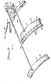
- FIGURE 3 is a greatly enlarged cross-sectional view through area 3 of the combustor of FIGURE 1 with portions of the combustor interior details being omitted for illustrative clarity;
- . Fig. 3A is an enlarged view of area 3A of Fig. -3 and illustrates a first sealing valve member of the actuation system moved to its closed position.
- Fig. 3B is an enlarged view of
area 3B of Fig. 3 and illustrates a second sealing valve member of the actuation system moved to its open position; - Fig. 4 is a fragmentary cross-sectional view taken through the combustor along line 4-4 of Fig. 3;
- Fig. 5 is an enlarged elevational view of a portion of the actuation system taken along line 5-5 of Figure 4,
- Fig. 6 is a cross-sectional view through the actuation system taken along line 6-6 of Fig. 4;
- Fig. 7 is an enlarged cross-sectional view through the actuation system taken along line 7-7 of Fig. 4; and
- Fig. 8 is a fragmentary isometric illustration of a portion of the actuation system which schematically depicts the selective movement of various of its components.
- Schematically illustrated in Fig. 1 are the primary components of a gas turbine propulsion engine 10 which embodies principles of the present invention. During operation of the engine, ambient air 12 is drawn into a
compressor 14 which is spaced apart from and rotationally coupled to a bladed turbine section 16 by an interconnectingshaft 18. Pressurizedair 20 discharged fromcompressor 14 is forced into an annular,reverse flow combustor 22 which circumscribes the turbine section 16 and an adjacent portion ofshaft 18. Theair 20 is mixed within the combustor withfuel 24, the resulting fuel-air mixture being continuously burned and discharged from the combustor across turbine section 16 in the form of hot, expandedgas 26. This expulsion of thegas 26 simultaneously drives the turbine and compressor, and provides the engine's propulsive thrust. - Conventional combustors used in aircraft jet propulsion engines are of fixed geometry construction and are designed to be operated only within a predetermined altitude-mach number flight envelope such as
envelope 28 bounded by thesolid line 30 in the graph of Fig. 2. If an attempt is made to operate the conventional combustor at higher altitudes or lower mach numbers than those within envelope 28 (i.e., within, for example, thecross-hatched area 32 bounded byline 30 and dashedline 36 in Fig. 2), the lean stability and altitude relight capability of the.combustor are adversely affected. More specifically, if a conventional, fixed geometry combustor were to be operated within the representative flightenvelope expansion area 32, the combustion process in the combustor would be subject to abrupt, unintended extinguishment, causing'an equally abrupt power loss. Compounding this rather serious problem, substantial difficulty would normally be encountered in relighting the combustor until the aircraft dropped back into thenormal flight envelope 28. - Not only is the upper boundary of a gas turbine propulsion engine's flight envelope limited by conventional fixed geometry combustor apparatus as just described, but certain other previously necessary combustor design compromises limit the engine's performance - even within the
design flight envelope 28. One such limitation arising from the use of fixed geometry high temperature rise combustors is the occurrence of engine ground starting difficulty - especially at low ambient temperatures. - As will now be described with reference to Figs. 3-8, the
combustor 22 of the present invention is of a unique, variable geometry construction which permits the engine 10 to be efficiently and reliably operated within the substantially expandedflight envelope - Referring to Fig. 3, the
combustor 22 includes a hollow, annularouter housing 36 having an annular radiallyouter sidewall 38 and an annular, radiallyinner sidewall 40 spaced apart from and connected tosidewall 38 by an annularupstream end wall 42. Positioned coaxially within thehousing 36 is an upstream end portion of an annular,hollow combustor liner 44 having a reverse flow configuration.Liner 44 has an annularupstream end wall 46 spaced axially inwardly from thehousing end wall 42, and annular radially outer andinner sidewalls liner end wall 46 and then curve radially inwardly through a full 180°. At their downstream termination, theliner sidewalls hot discharge gas 26 is expelled from the interior orcombustion flow passage 54 ofliner 44. - The interior of
housing 36 defines anintake plenum 56 which circumscribes the upstream end portion ofliner 44 as in- 7 dicated in Fig. 3.Compressor discharge air 20 is forced intoplenum 56 through an annular inlet opening 58 which circumscribes theliner 44 and is positioned at the left end ofcombustor 22. A portion of this pressurized air is used to cool theliner sidewalls sidewalls outer wall segments walls air 20 is forced inwardly throughopenings wall segments combustion flow passage 54, in a downstream direction, throughexit slots 48c, 50c formed between the skirted wall segments. - At the upstream end of the liner-44 is an annular
liner inlet plenum 60 which is positioned axially between theliner end wall 46 and an annular liner interior wall 62 which is axially spaced in a downstream direction from theliner end wall 46. Theplenum 60 opens radially outwardly through theouter liner sidewall 48 through a circumferentially spaced series of inlet slots 64 (only one of which is shown in Fig. 3) formed throughsidewall 48. Extending downstream from the interior wall 62 is a dome portion 54a of thecombustion flow passage 54 which is radially bounded by inner and outer annular cooling skirts 66, 68. Cooling skirts 66, 68 are spaced inwardly from the inner and outer liner sidewalls 50, 48, respectively, and define with the liner sidewalls axially extendingcooling passages combustion flow passage 54 as indicated in Fig. 3. Coolingpassage 70 communicates at its upstream end with theliner inlet plenum 60 through a circumferentially'spaced series of air passages 74 formed through the liner interior wall 62, while theannular cooling passage 72 communicates with theplenum 60 through a circumferentially spaced series ofair flow passages 76 also extending through the interior wall 62. In a manner subsequently described,compressor discharge air 20 is selectively admitted to theliner plenum 60 and is forced axially through theannular flow passages combustion flow passage 54 to thereby cool the inner wall surfaces of the liner dome portion 54a similarly to the cooling of the inner liner wall surfaces achieved by the cooling skirts 48a, 50a. - To inject
fuel 24 into the dome area 54a, a.circumferentially spaced series offuel nozzles 78 are utilized. Thenozzles 78 project axially inwardly through theliner end wall 46, theliner plenum 60, and the liner interior wall 62 into the dome area 54a (see also Fig. 4). Each of these fuel nozzles is of a piloted air blast type, being supplied by a pair offuel lines housing end wall 42. At the inner end of each of the nozzles is a pressure atomizing fuel outlet (not specifically illustrated) and an air blast fuel spray outlet (also not specifically illustrated). In a conventional manner the nozzles may be staged to deliver fuel through either of the atomizing or air blast outlets. - Coannularly circumscribing each of the
nozzles 78, and carried by the liner interior wall 62, are a pair ofannular air swirlers liner pleunum 60 radially inwardly of the cooling skirts 66, 68. Primary combustion air is admitted to theflow passage 54 through a circumferentially spaced series ofinlet orifices 88 positioned immediately downstream from the dome area 54a. At the left end of theliner 44 is anannular plenum 90 which opens outwardly into thehousing plenum 56 through a circumferentially spaced series ofslots 92 formed through theliner side wall 48, and communicates with thecombustion flow passage 54 through a circumferentially spaced series ofinlet passages 94 extending inwardly through thesidewall 48. - The previously described structure of the
combustor 44 uniquely permits its geometry to be effectively varied by selectively blocking or unblocking heinlet slots - Referring now to Figs. 3, 3A, 3B.and 8, to selectively block and unblock the liner
plenum inlet slots 64, a first sealing member in the form of avalve ring 96 is provided.Ring 96 coaxially circumscribes and outwardly overlies an upstream end portion of thecombustor liner 44 as best illustrated in Fig. 3.Ring 96 is axially movable relative to the combustor liner between a closed position illustrated in Fig. 3, and an open position illustrated in Fig. 3A. A left or forward axial portion 96a ofring 96 is radially outwardly enlarged and has formed therethrough a circumferentially spaced series of inlet slots 98 (Fig. 8). This forward portion 96a of thering 96 is slidably and sealingly engaged by apiston ring 100 carried by theouter liner wall 48, while the right orrear portion 96b ofring 96 is slidably and sealingly engaged by apiston ring 102 which is carried by theliner end wall 46. - At the left end of the combustor liner a
second sealing member 104 is provided for selectively blocking and unblocking theinlet slots 92.Ring 104 coaxially circumscribes and outwardly overlies theliner sidewall 48 for slidable axial movement therealong between a closed position indicated in Fig. 3Aand an open position shown in Fig. 3.. With the sealingring 104 in its closed position, theinlet ports 92 are blocked to preclude entry therethrough ofcompressor discharge air 20, an annular lip 104a on*thering 104 cooperating with an overlyingannular lip 106 on theliner side wall 48 to create a labyrinth seal 108 betweenring 104 andside wall 48, as shown in Fig. 3A, withring 104 in its closed position. - With the sealing
ring 96 in its closed position, the rearaxial portion 96b thereof blocks off the inlet slots 64 (Fig.3) to preclude entry ofcompressor discharge air 20 into theliner inlet plenum 60, the piston rings 100, 102 providing annular air flow seals between the combustor liner and thering 96 adjacent the opposite ends of theplenum 60. - Referring now to Figs. 3 and 8, the sealing rings 96, 104 are selectively moved in axially opposite directions (i.e. parallel to the center line or axis 110 of the combustor) between their previously described open and closed positions by a
novel actuation system 112. The actuation system includes an actuation orunison ring 114 which is positioned coaxially within thehousing plenum 56 immediately adjacent the outer ends of thefuel nozzles 78. Theactuation ring 114 is rotatably supported within theplenum 56 by a circumferentially spaced series of bearing support brackets 116 (only one of such brackets being illustrated in Fig. 4) which are positioned betweenadjacent nozzles 78 and externally secured to theliner end wall 46. Each of thesebrackets 116 carries a carbon bearing block 118 which is slidably received in a circumferential channel 120 (see Fig. 6) formed in the radially inner surface of theunison ring 114, thereby facilitating rotation ofring 114 within theplenum 56. - Selective rotation of the
unison ring 114 is achieved by the axial movement of acontrol rod 122 which extends into asmall housing 124, through seal means 126 carried by such housing, which is externally secured to theouter housing sidewall 38 over anopening 128 extending therethrough. 'Control rod 122 extends lengthwise generally tangentially to the outer surface ofhousing sidewall 38 and perpendicularly to the combustor axis. The inner end of thecontrol rod 122 is pivotally secured to one end of a connectingrod 130 which extends radially inwardly through thesidewall opening 128 and is secured at its inner end to theunison ring 114. As viewed in Fig. 4, inward axial movement of thecontrol rod 122, which may be achieved by conventional control means (not illustrated) positioned outside the combustor housing, moves the connectingrod 130 to the left within theopening 128 and causes a counter-clockwise rotation of theunison ring 114. In a similar manner, an outward axial movement of the control rod causes a clockwise rotation of the unison ring. - Such selective rotation of the
unison ring 114 is utilized to cause the opposite axial motion of the sealing rings 96, 104 by linking means in the form of four circumferentially spaced sets of actuatingrods 132, 134 (only one such rod set being illustrated in Figs. 3 and 8) which extend axially within thehousing sidewalls unison ring 114 by means of four circumferentially spaced bell crankmembers 136. - Referring again to Figs. 3 and 8, each of the four bell crank
members 136 has abase leg portion 138 which is pivoted at its outer end to the unison ring 114 (as at 140) and extends from its pivot point, in a generally axial direction toward thehousing end wall 42, to a radially outwardly directedtrunk portion 142 which is pivoted in asupport bracket 144 as indicated in phantom in Fig. 8. Each of the foursupport brackets 144 is secured to theliner end wall 46 between an adjacent pair ofnozzles 78 as can be best seen in Fig. 4. Like the previously described bearingbrackets 116, each of thesesupport brackets 144 also carries a carbon bearing block 118 (see Fig. 3) which slidably engages the inner surface of theunison ring 114. - Extending transversely in opposite directions from the bell crank member's
trunk portion 142 are a pair ofcontrol arms 146, 148 (Fig. 8). The outer end of eacharm 146 is pivotally connected to one end of anactuating rod 132 which is secured at its opposite end to thesealing ring 104. In a similar manner, the outer end of eacharm 148 is pivotally connected to one end of anactuating rod 134, the other end ofsuch actuating rod 134 being secured to the sealingring 96. - As viewed in Fig. 8, when the
control rod 122 is moved axially inwardly, the unison ring is rotated in a clockwise direction. This pivots the bell crankmember trunk portion 142 in a counter-clockwise direction within thesuppport bracket 144. This, in turn, simultaneously causes leftward axial motion of each of the actuatingrods 132, and rightward axial motion of each of the actuatingrods 134, thereby simultaneously moving the sealingring 104 leftwardly towards its closed position, and moving the sealingring 96 rightwardly towards its open position. Outward axial motion of thecontrol rod 122 causes opposite axial movement of each of the sealing rings 96, 104. - To laterally stabilize the much longer actuating
rods 132, each of them is slidably extended through a journal portion 144a of its associated support bracket 144 (Fig. 5) and an additional journal support 150 (Fig. 3) carried by theouter housing sidewall 38. Such journalling also rotationally stabilizes the sealingring 104, thereby assuring a smooth sliding motion thereof along theliner sidewall 48. A similar rotational stability is also provided to the sealingring 96 by means of a channel 152 (Fig. 5) which is formed in aguide member 154 secured to the sealingring 96, thechannel 152 slidably receiving a downturned lip portion 156 of support bracket 144 (see also Fig. 4). - During normal operation of the
combustor 22, theactuation system 112 is utilized to move the sealingring 96 to its open position (Fig. 3B) and to simultaneously move thesealing ring 104 to its closed position (Fig. 3A). With the sealing rings in their normal operating positions,compressor discharge air 20 in thehousing plenum 56 is forced inwardly through the sealingring inlet slots 98 into theliner plenum 60. From theplenum 60 enteringair 20 is forced outwardly through the domewall cooling slots annular air swirlers nozzles 78, further mixed with the primary combustion air entering through theprimary orifices 88, and continously burned. - The fuel richness within the combustor dome area 54a may be selectively varied both by variably staging the
fuel nozzles 78 and by moving the sealingring 96 toward its closed position, thereby blocking off a portion of the sealingring inlet slots 98. Such movement of the sealingring 96 toward its closed position simultaneously reduces air flow through thewall cooling slots swirler plates combustor 22 is substantially improved compared to conventional fixed geometry combustors, thus permitting reliable and efficient normal operation of the engine 10 within the expandedflight envelope portion 32 of Fig. 2. - Should combustion in the
combustor 22 be extinguished at altitude, the combustion is easily and rapidly reinitiated, even in the expandedflight envelope portion 32, by utilizing theactuation system 112 to move the sealing rings 96, 104 to their fully closed and fully opened positions, respectively, as depicted in Fig. 3. With the sealingring 96 in its fully closed position, all swirler air flow to the dome area 54a, and all cooling air flow through the skirteddome cooling slots nozzles 78 are then staged to their pilot position, andfuel 24 injected into the dome from the pressure atomizing outlets of thenozzles 78 is mixed with primary combustion air entering theorifices 88. This mixture is ignited by conventional igniter means 158 to reestablish combustion. - It is important to note that with the sealing
ring 96 in its fully closed position, and the nozzles staged to their pilot conditions, the fuel richness within thedome area 54 is maximized. Moreover, at the same time, the dome cooling is minimized, thereby maximizing the dome combustion temperature. These cooperating features of theimproved combustor 22 provide greatly improved altitude relight capabilities, thereby adding yet another measure of safety and reliability to the combustor when it is operated within the expandedflight envelope zone 32. - The altitude restart capabilities of the
combustor 22 are further enhanced when the sealingring 104 is brought to its fully opened positioned by theactuation system 112. During altitude relight procedures with conventional fixed geometry combustors, excess compressor discharge air is intentionally bypassed around the combustor and bled off to atmosphere. However, in the present invention, such compressor discharge air is uniquely utilised to assist in the altitude restart procedure. More specifically, with the sealingring 104 in its fully opened position, this previously wasted excess compressor discharge air is forced inwardly through theinlet slots 92, theplenum 90 and theinlet passages 94 into thecombustion flow passage 54. The entering compressor discharge air is then forced outwardly through thecombustor outlet opening 52 and across the bladed turbine section 16 to greatly assist in the "windmill" restarting of the engine 10. - During normal operation with the
seating ring 96 in its open position, the sealingring 104 is in its closed position so that the air for combustion is not extracted through the passages 9.4. - The previously described maximisation of the fuel richness and wall temperatures within the dome area 54a not only improves the altitude relight and Lean stability characteristics of the engine 10 but also substantially improves its ground start capabilities - especially in Low ambient temperature conditions.
- In summary, the present invention provides improved combustor apparatus, and associated operating methods, which eliminate or substantially reduce the stability and relight problems commonly associated with conventional fixed geometry combustors.
Claims (11)
Applications Claiming Priority (4)
| Application Number | Priority Date | Filing Date | Title |
|---|---|---|---|
| US400580 | 1982-07-22 | ||
| US400578 | 1982-07-22 | ||
| US06/400,578 US4497170A (en) | 1982-07-22 | 1982-07-22 | Actuation system for a variable geometry combustor |
| US06/400,580 US4532762A (en) | 1982-07-22 | 1982-07-22 | Gas turbine engine variable geometry combustor apparatus |
Publications (2)
| Publication Number | Publication Date |
|---|---|
| EP0100135A1 true EP0100135A1 (en) | 1984-02-08 |
| EP0100135B1 EP0100135B1 (en) | 1986-06-11 |
Family
ID=27017100
Family Applications (1)
| Application Number | Title | Priority Date | Filing Date |
|---|---|---|---|
| EP19830301586 Expired EP0100135B1 (en) | 1982-07-22 | 1983-03-22 | Combustor |
Country Status (2)
| Country | Link |
|---|---|
| EP (1) | EP0100135B1 (en) |
| DE (1) | DE3364029D1 (en) |
Cited By (12)
| Publication number | Priority date | Publication date | Assignee | Title |
|---|---|---|---|---|
| DE3942451A1 (en) * | 1989-12-22 | 1991-06-27 | Daimler Benz Ag | Gas turbine secondary air adjusting mechanism - has ports in tube, surrounding flame tube, controlled by throttle |
| EP0569300A1 (en) * | 1992-05-06 | 1993-11-10 | Societe Nationale D'etude Et De Construction De Moteurs D'aviation "Snecma" | Combustion chamber with adjustable passages for primary air |
| FR2704628A1 (en) * | 1993-04-29 | 1994-11-04 | Snecma | Combustion chamber comprising an oxidant injection system with variable geometry. |
| EP0691512A2 (en) * | 1994-07-05 | 1996-01-10 | R. Jan Mowill | Annular premix combustor for gasturbines |
| US5765363A (en) * | 1993-07-07 | 1998-06-16 | Mowill; R. Jan | Convectively cooled, single stage, fully premixed controllable fuel/air combustor with tangential admission |
| US5924276A (en) * | 1996-07-17 | 1999-07-20 | Mowill; R. Jan | Premixer with dilution air bypass valve assembly |
| EP0967437A1 (en) * | 1998-06-24 | 1999-12-29 | Entreprise Generale De Chauffage Industriel Pillard | Improvement to combustion apparatus with several combustion air inlet ducts |
| US6220034B1 (en) | 1993-07-07 | 2001-04-24 | R. Jan Mowill | Convectively cooled, single stage, fully premixed controllable fuel/air combustor |
| RU2505749C1 (en) * | 2012-07-27 | 2014-01-27 | Федеральное государственное унитарное предприятие "Центральный институт авиационного моторостроения им. П.И. Баранова" | Gas turbine engine combustion chamber and method of its operation |
| RU2513527C1 (en) * | 2012-12-20 | 2014-04-20 | Федеральное государственное унитарное предприятие "Центральный институт авиационного моторостроения им. П.И. Баранова" | Gas turbine engine combustion chamber and method of its operation |
| RU2531477C1 (en) * | 2013-08-30 | 2014-10-20 | Федеральное государственное казенное военное образовательное учреждение высшего профессионального образования "Военный учебно-научный центр Военно-воздушных сил "Военно-воздушная академия имени профессора Н.Е. Жуковского и Ю.А. Гагарина" (г. Воронеж) Министерства обороны Российской Федерации | Device to burn fuel in gas turbine engine |
| RU2625076C1 (en) * | 2016-02-08 | 2017-07-11 | Николай Борисович Болотин | Combustion chamber of gas turbine engine and means of air activation |
Citations (4)
| Publication number | Priority date | Publication date | Assignee | Title |
|---|---|---|---|---|
| US3919838A (en) * | 1974-11-04 | 1975-11-18 | Gen Motors Corp | Combustion control |
| US3927520A (en) * | 1974-02-04 | 1975-12-23 | Gen Motors Corp | Combustion apparatus with combustion and dilution air modulating means |
| US3930368A (en) * | 1974-12-12 | 1976-01-06 | General Motors Corporation | Combustion liner air valve |
| EP0026594A1 (en) * | 1979-09-28 | 1981-04-08 | General Motors Corporation | Low emissions prevaporization type combustor assembly |
-
1983
- 1983-03-22 EP EP19830301586 patent/EP0100135B1/en not_active Expired
- 1983-03-22 DE DE8383301586T patent/DE3364029D1/en not_active Expired
Patent Citations (4)
| Publication number | Priority date | Publication date | Assignee | Title |
|---|---|---|---|---|
| US3927520A (en) * | 1974-02-04 | 1975-12-23 | Gen Motors Corp | Combustion apparatus with combustion and dilution air modulating means |
| US3919838A (en) * | 1974-11-04 | 1975-11-18 | Gen Motors Corp | Combustion control |
| US3930368A (en) * | 1974-12-12 | 1976-01-06 | General Motors Corporation | Combustion liner air valve |
| EP0026594A1 (en) * | 1979-09-28 | 1981-04-08 | General Motors Corporation | Low emissions prevaporization type combustor assembly |
Cited By (18)
| Publication number | Priority date | Publication date | Assignee | Title |
|---|---|---|---|---|
| DE3942451A1 (en) * | 1989-12-22 | 1991-06-27 | Daimler Benz Ag | Gas turbine secondary air adjusting mechanism - has ports in tube, surrounding flame tube, controlled by throttle |
| EP0569300A1 (en) * | 1992-05-06 | 1993-11-10 | Societe Nationale D'etude Et De Construction De Moteurs D'aviation "Snecma" | Combustion chamber with adjustable passages for primary air |
| FR2690977A1 (en) * | 1992-05-06 | 1993-11-12 | Snecma | Combustion chamber having adjustable primary combustion inlet passages. |
| US5317863A (en) * | 1992-05-06 | 1994-06-07 | Societe Nationale D'etude Et De Construction De Moteurs D'aviation "S.N.E.C.M.A." | Gas turbine combustion chamber with adjustable primary oxidizer intake passageways |
| FR2704628A1 (en) * | 1993-04-29 | 1994-11-04 | Snecma | Combustion chamber comprising an oxidant injection system with variable geometry. |
| US5398495A (en) * | 1993-04-29 | 1995-03-21 | Societe Nationale D'etude Et De Construction De Moteurs D'aviation (S.N.E.C.M.A.) | Combustion chamber with variable oxidizer intakes |
| US5765363A (en) * | 1993-07-07 | 1998-06-16 | Mowill; R. Jan | Convectively cooled, single stage, fully premixed controllable fuel/air combustor with tangential admission |
| US6220034B1 (en) | 1993-07-07 | 2001-04-24 | R. Jan Mowill | Convectively cooled, single stage, fully premixed controllable fuel/air combustor |
| EP0691512A3 (en) * | 1994-07-05 | 1997-05-07 | Mowill Rolf Jan | Annular premix combustor for gasturbines |
| EP0691512A2 (en) * | 1994-07-05 | 1996-01-10 | R. Jan Mowill | Annular premix combustor for gasturbines |
| CN1065947C (en) * | 1994-07-05 | 2001-05-16 | R·简莫维尔 | Gas turbine engine with improved convectively cooled, single stage, fully premixed fuel/air combustion system |
| US5924276A (en) * | 1996-07-17 | 1999-07-20 | Mowill; R. Jan | Premixer with dilution air bypass valve assembly |
| EP0967437A1 (en) * | 1998-06-24 | 1999-12-29 | Entreprise Generale De Chauffage Industriel Pillard | Improvement to combustion apparatus with several combustion air inlet ducts |
| FR2780488A1 (en) * | 1998-06-24 | 1999-12-31 | Pillard Chauffage | IMPROVEMENT TO COMBUSTION APPLIANCES COMPRISING SEVERAL FUEL TRANSPORT DUCTS |
| RU2505749C1 (en) * | 2012-07-27 | 2014-01-27 | Федеральное государственное унитарное предприятие "Центральный институт авиационного моторостроения им. П.И. Баранова" | Gas turbine engine combustion chamber and method of its operation |
| RU2513527C1 (en) * | 2012-12-20 | 2014-04-20 | Федеральное государственное унитарное предприятие "Центральный институт авиационного моторостроения им. П.И. Баранова" | Gas turbine engine combustion chamber and method of its operation |
| RU2531477C1 (en) * | 2013-08-30 | 2014-10-20 | Федеральное государственное казенное военное образовательное учреждение высшего профессионального образования "Военный учебно-научный центр Военно-воздушных сил "Военно-воздушная академия имени профессора Н.Е. Жуковского и Ю.А. Гагарина" (г. Воронеж) Министерства обороны Российской Федерации | Device to burn fuel in gas turbine engine |
| RU2625076C1 (en) * | 2016-02-08 | 2017-07-11 | Николай Борисович Болотин | Combustion chamber of gas turbine engine and means of air activation |
Also Published As
| Publication number | Publication date |
|---|---|
| DE3364029D1 (en) | 1986-07-17 |
| EP0100135B1 (en) | 1986-06-11 |
Similar Documents
| Publication | Publication Date | Title |
|---|---|---|
| US4497170A (en) | Actuation system for a variable geometry combustor | |
| US4532762A (en) | Gas turbine engine variable geometry combustor apparatus | |
| US4567724A (en) | Variable geometry combustor apparatus and associated methods | |
| US8011188B2 (en) | Augmentor with trapped vortex cavity pilot | |
| EP1808644B1 (en) | Externally fueled trapped vortex cavity augmentor | |
| US5694767A (en) | Variable slot bypass injector system | |
| US3931707A (en) | Augmentor flameholding apparatus | |
| EP1605207B1 (en) | Thrust augmentor for gas turbine engines | |
| EP0100135B1 (en) | Combustor | |
| US5311735A (en) | Ramjet bypass duct and preburner configuration | |
| US5309710A (en) | Gas turbine combustor having poppet valves for air distribution control | |
| US4899539A (en) | Flow mixer and flame stabilizer for a turbofan engine | |
| US4594848A (en) | Gas turbine combustor operating method | |
| US6981361B2 (en) | Methods for operating gas turbine engines | |
| EP2400221B1 (en) | Ejector purge of cavity adjacent exhaust flowpath | |
| US4502636A (en) | Variable geometry ejector nozzle for turbomachines | |
| US4502637A (en) | Turbomachine ejector nozzle with thrust reverser | |
| US5481867A (en) | Combustor | |
| US4170109A (en) | Thrust augmentor having swirled flows for combustion stabilization | |
| US4170111A (en) | Thrust augmentor | |
| US2918794A (en) | Flameholder | |
| US4527390A (en) | Low loss duct burner | |
| US11828469B2 (en) | Adaptive trapped vortex combustor | |
| GB2503184A (en) | Combustor |
Legal Events
| Date | Code | Title | Description |
|---|---|---|---|
| PUAI | Public reference made under article 153(3) epc to a published international application that has entered the european phase |
Free format text: ORIGINAL CODE: 0009012 |
|
| AK | Designated contracting states |
Designated state(s): DE FR GB IT SE |
|
| 17P | Request for examination filed |
Effective date: 19840727 |
|
| ITF | It: translation for a ep patent filed |
Owner name: BARZANO' E ZANARDO ROMA S.P.A. |
|
| GRAA | (expected) grant |
Free format text: ORIGINAL CODE: 0009210 |
|
| AK | Designated contracting states |
Kind code of ref document: B1 Designated state(s): DE FR GB IT SE |
|
| REF | Corresponds to: |
Ref document number: 3364029 Country of ref document: DE Date of ref document: 19860717 |
|
| ET | Fr: translation filed | ||
| PLBE | No opposition filed within time limit |
Free format text: ORIGINAL CODE: 0009261 |
|
| STAA | Information on the status of an ep patent application or granted ep patent |
Free format text: STATUS: NO OPPOSITION FILED WITHIN TIME LIMIT |
|
| 26N | No opposition filed | ||
| ITTA | It: last paid annual fee | ||
| PGFP | Annual fee paid to national office [announced via postgrant information from national office to epo] |
Ref country code: FR Payment date: 19911223 Year of fee payment: 10 |
|
| PGFP | Annual fee paid to national office [announced via postgrant information from national office to epo] |
Ref country code: GB Payment date: 19920312 Year of fee payment: 10 |
|
| PGFP | Annual fee paid to national office [announced via postgrant information from national office to epo] |
Ref country code: SE Payment date: 19920319 Year of fee payment: 10 |
|
| PGFP | Annual fee paid to national office [announced via postgrant information from national office to epo] |
Ref country code: DE Payment date: 19920430 Year of fee payment: 10 |
|
| PG25 | Lapsed in a contracting state [announced via postgrant information from national office to epo] |
Ref country code: GB Effective date: 19930322 |
|
| PG25 | Lapsed in a contracting state [announced via postgrant information from national office to epo] |
Ref country code: SE Effective date: 19930323 |
|
| GBPC | Gb: european patent ceased through non-payment of renewal fee |
Effective date: 19930322 |
|
| PG25 | Lapsed in a contracting state [announced via postgrant information from national office to epo] |
Ref country code: FR Effective date: 19931130 |
|
| PG25 | Lapsed in a contracting state [announced via postgrant information from national office to epo] |
Ref country code: DE Effective date: 19931201 |
|
| REG | Reference to a national code |
Ref country code: FR Ref legal event code: ST |
|
| EUG | Se: european patent has lapsed |
Ref document number: 83301586.0 Effective date: 19931008 |