EP0966124B1 - Verfahren und Einrichtung zum Senden und Empfangen von punktierten, faltungskodierten Daten - Google Patents
Verfahren und Einrichtung zum Senden und Empfangen von punktierten, faltungskodierten Daten Download PDFInfo
- Publication number
- EP0966124B1 EP0966124B1 EP99111667A EP99111667A EP0966124B1 EP 0966124 B1 EP0966124 B1 EP 0966124B1 EP 99111667 A EP99111667 A EP 99111667A EP 99111667 A EP99111667 A EP 99111667A EP 0966124 B1 EP0966124 B1 EP 0966124B1
- Authority
- EP
- European Patent Office
- Prior art keywords
- transmission
- reception
- puncturing
- data series
- series
- Prior art date
- Legal status (The legal status is an assumption and is not a legal conclusion. Google has not performed a legal analysis and makes no representation as to the accuracy of the status listed.)
- Expired - Lifetime
Links
Images




Classifications
-
- H—ELECTRICITY
- H04—ELECTRIC COMMUNICATION TECHNIQUE
- H04L—TRANSMISSION OF DIGITAL INFORMATION, e.g. TELEGRAPHIC COMMUNICATION
- H04L1/00—Arrangements for detecting or preventing errors in the information received
- H04L1/004—Arrangements for detecting or preventing errors in the information received by using forward error control
- H04L1/0056—Systems characterized by the type of code used
- H04L1/0059—Convolutional codes
-
- H—ELECTRICITY
- H04—ELECTRIC COMMUNICATION TECHNIQUE
- H04L—TRANSMISSION OF DIGITAL INFORMATION, e.g. TELEGRAPHIC COMMUNICATION
- H04L1/00—Arrangements for detecting or preventing errors in the information received
- H04L1/004—Arrangements for detecting or preventing errors in the information received by using forward error control
- H04L1/0056—Systems characterized by the type of code used
- H04L1/0067—Rate matching
- H04L1/0068—Rate matching by puncturing
- H04L1/0069—Puncturing patterns
-
- H—ELECTRICITY
- H04—ELECTRIC COMMUNICATION TECHNIQUE
- H04L—TRANSMISSION OF DIGITAL INFORMATION, e.g. TELEGRAPHIC COMMUNICATION
- H04L1/00—Arrangements for detecting or preventing errors in the information received
- H04L1/02—Arrangements for detecting or preventing errors in the information received by diversity reception
- H04L1/06—Arrangements for detecting or preventing errors in the information received by diversity reception using space diversity
-
- H—ELECTRICITY
- H04—ELECTRIC COMMUNICATION TECHNIQUE
- H04L—TRANSMISSION OF DIGITAL INFORMATION, e.g. TELEGRAPHIC COMMUNICATION
- H04L1/00—Arrangements for detecting or preventing errors in the information received
- H04L1/08—Arrangements for detecting or preventing errors in the information received by repeating transmission, e.g. Verdan system
Definitions
- the present invention relates to a digital wireless transmission and reception system, a transmission and reception device, and a method of transmission and reception, in which quality of communication is improved.
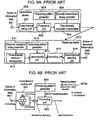
- a series of information data 851 to be transmitted is punctured (thinning-out process) in a unit of a fixed amount of data block by a puncturing unit 802 in order to reduce an amount of communication traffic in a transmission pathway, after it is convolution-coded by a convolutional coding unit 801.
- a puncturing (thinning-out) location within the data block is stored as a puncturing pattern in a puncturing pattern generator 803, from where it is supplied to the puncturing unit 802.
- a series of input information data ⁇ a 0 , b 0 , c 0 , d 0 , ... ⁇ is converted into a series of convolution-coded data ⁇ a 1 , a 2 , b1, b 2 , c 1 , c 2 , d 1 , d 2 , « ⁇ by the convolutional coding unit 801 having a constraint length of 3 and a coding rate of 1/2.
- the puncturing unit 802 removes b 2 , d 1 , etc., and outputs a series of punctured data ⁇ a 1 , a 2 , b 1 , c 1 , c 2 , d 2 , Vietnamese ⁇ , when a puncturing pattern 803b is supplied from the puncturing pattern generator 803.
- This series ofpunctured data is a combination of a series of data ⁇ a 1 , b 1 , c 1 , e 1 , Vietnamese ⁇ , which is obtained by deleting data corresponding to a 0 position in an upper row of the puncturing pattern 803b from a series of data ⁇ a 1 , b 1 , c 1 , d 1 , e 1 , whereas ⁇ corresponding to the upper row of the puncturing pattern 803b out of the foregoing series of convolution-coded data, and another series of data ⁇ a 2 , c 2 , d 2 , e 2 , bib ⁇ , which is obtained by deleting data corresponding to a 0 position in a lower row of the puncturing pattern 803b from a series of data ⁇ a 2 , b 2 , c 2 , d 2 , e 2 , ...... ⁇ corresponding to the lower row of the puncturing pattern 803b out of the series of convolution-coded data.
- a time-diversity modulator / transmitter 804 repeats modulation and transmission of the series of punctured data for a predetermined number of times in response to a diversity transmission timing control signal supplied by a diversity transmission timing controller 805 at intervals of a predetermined time.
- the predetermined time for the transmission device 800 to repeat the time-diversity transmission is set in advance with a diversity reception timing controller 811, so that the diversity reception timing controller 811 outputs a timing control signal for starting a time-diversity reception according to the set time.
- a time-diversity receiver / demodulator 812 receives and demodulates a signal transmitted repeatedly in response to the control signal of a time-diversity reception timing, and outputs a series of demodulated data of every diversity branch (every repeat time).
- a puncturing pattern generator 813 stores a puncturing pattern, which is identical to the puncturing pattern 803b used in the puncturing unit 802 of the transmission device.
- a depuncturing unit 814 uses this puncturing pattern to depuncture the series of demodulated data of every diversity branch, and outputs a series of depunctured data of every diversity branch.
- the depuncturing is a process in which the punctured position is filled with a dummy data such as a value of 0 corresponding to a middle value between the soft decision value of -7 corresponding to a mark and the soft decision value of +7 corresponding to a space, for example.
- the depuncturing unit 814 outputs a series of depunctured data ⁇ a 1 , a 2 , b 1 , 0, c 1 , c 2 , 0, d 2 , ... ⁇ .
- the series of depunctured data of every diversity branch obtained here is combined symbol by symbol in a unit of block by a combining unit 815, and they are convolution-decoded with a method such as the Viterbi soft quantization by a convolutional decoding unit 816, which in turn outputs a series of decoded information data.
- a method such as the Viterbi soft quantization by a convolutional decoding unit 816, which in turn outputs a series of decoded information data.
- the depuncturing and the combining are reversed in their order of transaction.
- the devices can thus achieve an improvement in quality of communication for both of the error-correction coding and diversity with the structure as described above, by performing punctured-convolution-coding and time-diversity transmission on the information data to be transmitted, and also combining and depunctured-convolution-decoding after time-diversity reception of the data at the receiving side.
- Figs. 8A and 8B punctures certain identical locations in the series of convolution-coded data (error-correction code word) in each of the repeated transmissions by way of the time-diversity transmission. Therefore, these certain punctured locations and vicinity of them become susceptible to noises, as they become low in likelihood when convolution-decoding them, since they are treated as values having a large length between codes from both of the mark and the space at the receiving side.
- the present invention is intended to solve the above problems and it aims at preventing a likelihood of certain information data from declining by adopting a different puncturing pattern for each of diversity branches when transmitting and receiving mainly information data by a combination of the punctured convolution-coding and the diversity, thereby improving quality of communication.
- the transmission and reception system, the transmission and/or reception device, and the method of transmission and/or reception executes the diversity transmission and reception of a plurality of different series of error-correction code word, as individual diversity branch data, by obtaining them through puncturing and convolution-coding the identical series of information data with different forms of puncturing patterns. Accordingly, the present invention is able to prevent a likelihood of certain information data from declining, and to further improve a quality of communication.
- the present invention relates to a transmission and reception system, a transmission and reception device and a method of transmission and reception, which realize an improvement in quality of communication by taking steps of:
- a first exemplary embodiment of the present invention relates to a time-diversity transmission and reception system for transmitting and receiving the above-cited plurality of different series of punctured data via a plurality of paths with carrier waves of the same frequency (same assigned range of frequency) but different in time (allotted time for transmission).
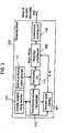
- Fig. 1A depicts a structure of a time-diversity transmission and reception system of the first exemplary embodiment
- Fig. 1B is a drawing for use in describing an essential part of the same.
- a primary difference of the present structure from that shown in Figs. 8A and 8B as described in the prior art system is that the puncturing pattern generator provided in each of the transmission device and the receiving device for generating a single form of the puncturing pattern is replaced by a multiple puncturing pattern generator for generating a plurality of puncturing patterns in various forms.
- the present embodiment is an example in which transmission and reception are made via two paths in order to simplify the description, a number of paths can be expanded easily without impairing the universality.
- a convolutional coding unit 101 convolution-codes a series of input information data 121, and outputs it as a series of convolution-coded data 125.
- the convolutional coding unit 101 in Fig. 1B is an example of circuit structure for convolution coding in a constraint length of 3 and a coding rate of 1/2.
- a multiple puncturing pattern generator 102 generates two forms of puncturing patterns having an identical puncturing rate, but different in block pattern of puncturing with each other. For instance, it generates two different puncturing patterns, a pattern A, 102a, and a pattern B, 102b, both having a same puncturing rate of 17/22 (a number of bits after puncturing / a number of bits before the puncturing), as shown in Fig. 1B.
- a numeral "0" indicates a location where the puncturing (thinning-out) is made within the puncturing patterns, and the puncturing locations are set in a manner that they do not overlap with each other between the patterns A and B.
- a puncturing unit 103 punctures the series of convolution-coded data 125 by using the two puncturing patterns, the pattern A, 102a, and the pattern B, 102b, and outputs respective series of punctured data 126a and 126b.
- the foregoing structure comprises the multiple puncturing pattern generator 102 and the puncturing unit 103 as being two separate blocks, the two functions can be combined into one block.
- the puncturing unit may have the function of generating plural forms of puncturing patterns as well as the function of puncturing.
- a diversity transmission timing controller 104 outputs two series of diversity transmission timing control signal 123 for the transmission device 100 to make time-diversity transmission at intervals of a predetermined time.
- a time-diversity modulator / transmitter 105 carries out the time-diversity transmission twice in response to each of the two orders of diversity transmission timing control signal 123 delivered by the diversity transmission timing controller 104 by using the series of punctured data 126a for a first data of the time-diversity modulation and transmission and the series of punctured data 126b for a second data of the time-diversity modulation and transmission.
- the predetermined time for the transmission device 100 to carry out the time-diversity transmission is set in advance with a diversity reception timing controller 111 of a receiving device 110, so that the controller 111 outputs a diversity reception timing control signal 124 twice on time for a start of time-diversity reception.
- a time-diversity receiver / demodulator 112 receives and demodulates the time-diversity transmitted signal in response to the diversity reception timing control signal 124, and outputs two series of demodulated data 127a and 127b of every diversity branch.
- a multiple puncturing pattern generator 113 generates two forms of puncturing patterns that are identical to those produced by the multiple puncturing pattern generator 102 of the transmission device 100.
- a depuncturing unit 114 depunctures the series of demodulated data 127a and 127b by using the puncturing patterns 102a and 102b supplied by the multiple puncturing pattern generator 113, one after another, and outputs series of depunctured data 128a and 128b.
- digital values in the series of demodulated data are output with their original values for unpunctured locations in the puncturing patterns, and a middle value between values of a mark and a space is inserted in each of the punctured locations. For instance, if individual symbols in the series of demodulated data are output in quantized soft decision values in a resolution of four bits, the mark and the space have values of -7 and +7 respectively, and a middle value between them corresponds to "0".
- the depuncturing unit 114 may have the function of generating two forms of puncturing patterns that are identical to those generated by the multiple puncturing pattern generator 102 of the transmission device 100, as well as the function of depuncturing.
- a combining unit 115 compounds the series of depunctured data 128a and 128b of every diversity branch, symbol by symbol in a unit of block.
- two 4 bits of digital data are added together.
- the addition of digital values in locations of the specific symbols does not leave the value "0" intact, since the locations where the value "0" is inserted in the depuncturing process differ between the two series of depunctured data 128a and 128b, as a matter of course.
- a convolutional decoding unit 116 decodes the series of combined results output by the combining unit 115 with a method such as the Viterbi soft quantization and the like means, and outputs a decoded series of information data 122.
- the present exemplary embodiment of this invention obtains two different series of punctured data by puncturing identical series of information data with two different forms of puncturing patterns, and executes time-diversity transmission of the obtained series of data as transmission data of individual diversity branches.
- a receiver compounds the transmitted data after depuncturing them by using two different forms of puncturing patterns, which are identical to those of the transmission side, and carries out convolution-decoding.
- the invention prevents a reduction of likelihood from concentrating on certain information data, since the punctured locations differ between individual diversity branches, so as to improve quality of the communication.
- a concept of the present exemplary embodiment is adaptable even to a structure, in which a number of puncturing patterns generated by the multiple puncturing pattern generator of the transmission device and the receiving device is increased to three forms or more, and a number of branches for the time-diversity transmission and reception is increased to three or more, so long as these branches include different puncturing patterns.
- Fig. 1B showing an example of circuit structure for the convolution coding in a constraint length of 3 and a coding rate of 1/2, and describes the puncturing as being made in a puncturing rate of 17/22, they are not restrictive as it is needless to mention.
- puncturing locations are said to be not overlapping among the plurality of puncturing patterns in the described embodiment, this is not restrictive, as some of the puncturing locations may overlap.
- the system can be constructed in a manner that the convolutional coding unit is supplied with a series of data processed by other error-correction coding or error-detection coding as the series of information data.
- the system may comprise a processing unit for interleaving and/or another unit for composing a burst, inserted between the puncturing unit and the modulator / transmitter.
- a second exemplary embodiment relates to an improvement of the multiple puncturing pattern generator in the time-diversity transmission and reception system of the first exemplary embodiment.
- the present system produces a reference matrix for generating a puncturing pattern at first, and generates plural forms of puncturing patterns by converting the reference matrix.
- Fig. 2A shows an internal structure of a multiple puncturing pattern generator (corresponding to the generators 102 and 113 in Figs. 1A and 1B) of the second exemplary embodiment.
- a reference matrix generator 201 is for generating a matrix for use as a reference when generating a plurality of puncturing patterns
- a matrix 201 a is an example of the reference matrix generated by it.
- a matrix converter 202 outputs a plurality of puncturing patterns by converting a row, a column or matrix elements of the reference matrix 201 a according to a predetermined process.
- the matrix converter 202 outputs two forms of puncturing patterns 202a and 202b by exchanging rows in the reference matrix 201 a. That is, the multiple puncturing pattern generator 102 first generates a matrix data from the reference matrix 201a without exchanging any of the rows, and outputs it as the puncturing pattern 202a. It then exchanges between a first row and a second row of the reference matrix 201 a, and outputs it as the puncturing pattern 202b.
- the structure and function of the time-diversity transmission and reception system of the second exemplary embodiment, other than the foregoing, remain the same as those of Figs. 1A and 1B.
- the system is able to save a memory capacity as compared to the system of the first exemplary embodiment, since it stores only one matrix as a reference for the multiple puncturing pattern generator to generate a plurality of puncturing patterns.
- the matrix converter adopts a method for exchanging matrix elements in rows of the reference matrix, this is not restrictive, and it may use a method of generating a plurality of puncturing patterns by exchanging column by column, as shown in Fig. 2B. There are also other methods of generating a plurality of puncturing patterns such as one that combines a plurality of rows in a predetermined order.
- a third exemplary embodiment relates to an improvement of the combining unit in the receiving device of the time-diversity transmission and reception system of the first exemplary embodiment.
- the present system obtains a result of combining by weighting a series of depunctured data according to a level of receiving signal, and adding it symbol by symbol.
- Fig. 3 shows a structure of a receiving device 310 in a time-diversity transmission and reception system of the third exemplary embodiment.
- a reception level memory 301 measures a level of receiving signal at a time-diversity receiver / demodulator 112 in response to a diversity reception timing control signal supplied by a diversity reception timing controller 111, and stores a result of the measurement for every diversity branch.
- the reception level memory 301 stores reception levels R1 and R2 for each of the time-diversity signals transmitted twice.
- a magnitude of weighting is classified into three steps of "large”, “medium” and “small” according to the reception level with their respective weighting factors of "1", “1/2” and “1/4", and the reception levels R1 and R2 are of magnitudes corresponding to "large” and “medium” respectively.
- a weighting factor W1 for the first diversity branch becomes “1”
- a weighting factor W2 for the second diversity branch becomes "1/2" at the weighting / combining unit 302.
- the present exemplary embodiment of the invention is expected to achieve an effectiveness equivalent to the maximum-ratio combining diversity, since it compounds depunctured data after weighting the data according to reception levels for each diversity branch of the received time-diversity signal, when combining the depunctured data.
- the foregoing example of the present exemplary embodiment has chosen a three-step classification for reception level with respective weighting factors of "1", "1/2" and "1/4", this is not exclusive.
- the classification can be set for any number of steps, and the weighting factors can be of any values so long as they correspond with the reception levels.
- a fourth exemplary embodiment relates to a code division multiplex signal transmission and reception system for transmitting and receiving the above-cited plurality of different series of punctured data with a plurality of paths for code division multiplex signal.
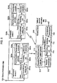
- Fig. 4 shows a structure of a transmission and reception system of the fourth exemplary embodiment.
- the system of Fig. 4 is provided with a code division multiplex signal transmitter 401 for code-division-multiplexing and transmitting a predetermined plural number of series of punctured data fed in it, in place of the diversity transmission timing controller 104 and the time-diversity modulator / transmitter 105 in the transmission device 100 of Fig. 1A.
- the system is also provided with a code division multiplex signal receiver 402 for receiving and demodulating individual signals transmitted with code-division-multiplexing and outputting a series of demodulated data, in place of the diversity reception timing controller 111 and the time-diversity receiver / demodulator 112 in the receiving device 110 of Fig. 1A.
- the transmission and reception system constituted as above will be described hereinafter for the portions that operate differently from that of the first exemplary embodiment.
- the transmission device 400 transmits a plural variety of punctured data series output from a puncturing unit 103 after they are code-division-multiplexed and spread-modulated by the code division multiplex signal transmitter 401.
- the receiving device 410 receives the transmitted signals multiplexed by code-division multiplexing, demodulates each of the multiplexed signals with a despreading process by the code division multiplex signal receiver 402, and supplies a predetermined plural number of series of demodulated data to a depuncturing unit 114. All other operations in the Fig.4 are same as those of Figs. 1A and 1B.
- this exemplary embodiment of the present invention enables the system to improve quality of communication in the like manner as the one using time-diversity transmission and reception, since it carries out transmission and reception of a plurality of different series of punctured and convolution-coded data with the code division multiplexing instead of the time-diversity transmission and reception.
- a fifth exemplary embodiment relates to a path-diversity transmission and reception system, in which a plurality of transmission devices transmits the above-described plurality of different series of punctured data via a plurality of paths, and a receiving device receives the same.
- FIG. 5 shows a structure of a transmission and reception system of the fifth exemplary embodiment.
- a path-diversity transmission system comprises two units of transmission devices 500a and 500b for processing and modulating identical series of information data, and transmitting them in a manner to avoid overlapping in time.
- a puncturing pattern generator in each of the transmission devices is adapted to generate a puncturing pattern having the same puncturing rate but in a different form from each other.
- a puncturing pattern generator 502a generates a puncturing pattern that is identical to the puncturing pattern 102a in Fig. 1B, and a puncturing pattern generator 502b generates a puncturing pattern identical to the pattern 102b in the same figure.
- Convolutional coding units 501a and 501b in the two transmission devices convolution-code a series of information data 521 fed in them, and output series of convolution-coded data.
- a puncturing unit 503a punctures the obtained series of convolution-coded data by using the puncturing pattern A, 102a, of Fig. 1B supplied from the puncturing pattern generator 502a.
- a puncturing unit 503b in the transmission device 500b punctures the obtained series of convolution-coded data by using the puncturing pattern B, 102b, of Fig. 1 B supplied from the puncturing pattern generator 502b.
- Modulator / transmitters 505a and 505b modulate and transmit the series of punctured data obtained in the foregoing puncturing units according to information for transmission timings and transmission frequencies supplied from transmission controllers 504a and 504b in the individual transmission devices.
- Each of the signals transmitted by the transmission devices 500a and 500b has approximately same frequency, and is so arranged not to overlap in transmission timing with each other.
- a receiving device 510 receives and demodulates the signals transmitted by the two transmission devices 500a and 500b according to information for a predetermined reception timing and a receiving frequency supplied from a reception controller 511, and outputs respective series of demodulated data.
- a depuncturing unit 114 depunctures the series of demodulated data of the signal transmitted by the transmission device 500a with a puncturing pattern, which is identical to the pattern 102a generated by the puncturing pattern generator 502a, out of the two predetermined forms of different puncturing patterns supplied by a multiple puncturing pattern generator 113, and the series of demodulated data of the signal transmitted by the transmission device 500b with a puncturing pattern that is identical to the pattern 102b generated by the puncturing pattern generator 502b, and outputs respective series of depunctured data.
- a compounding unit 115 compounds a plural series of the depunctured data delivered from the depuncturing unit 114, symbol by symbol in a unit of block.
- a convolutional decoding unit 116 then convolution-decodes the obtained series of combined results, and outputs a series of decoded information data 522.
- the transmission devices when transmitting identical series of information data with a plurality of transmission devices, transmit the identical series of information data after puncturing and convolution-coding each of the data series with a different puncturing pattern among the transmission devices.
- a receiving device depunctures the signals transmitted by each of the transmission devices with the identical patterns that are used by the transmission devices.
- the invention is able to vary puncturing locations from one transmission device to another, so as to avoid a reduction in likelihood of certain information data, and to further improve quality of the communication.
- the transmission controllers 504a and 504b in the present exemplary embodiment are so arranged that transmission frequency from each of the transmission devices are approximately equal, and their transmission timings do not overlap with each other, these are not restrictive. Instead, the transmission frequency from the transmission devices may be arranged so as not to overlap with each other, while maintaining the transmission timings approximately equal between the transmission devices. Or, both of the transmission timings and the transmission frequency can be arranged not to overlap between the transmission devices. In these cases, information for reception timings and receiving frequencies need to be set with the reception controller 511 according to the information of the transmission side.
- the transmission devices may be provided with code-division multiplex signal transmitters, instead of the modulator / transmitters 505a and 505b in each of the transmission devices, for modulating and transmitting the series of punctured data with code-division multiplexing according to information for transmission timing and transmission frequency, while maintaining the transmission timings and the transmission frequencies set by the transmission controllers 504a and 504b in the transmission devices approximately equal.
- the receiving device comprises a code-division multiplex signal receiver, instead of the receiver / demodulator 512, for outputting a series of demodulated data by receiving and demodulating every signals transmitted with code-division multiplexing from each of the transmission devices by way of extracting them with the despreading process, while maintaining the reception timings and the reception frequencies set with the reception controller 511 for the signals transmitted by the transmission devices approximately equal.
- a system can be constituted with a plurality of transmission devices for transmitting identical series of information data by code-division multiplexing, and a receiving device for receiving and demodulating every code-division multiplexed signals.
- the system of the present exemplary embodiment is provided with two transmission devices, this is not exclusive and three or more transmission devices can be provided, as long as puncturing patterns used by the individual transmission devices are generated in different varieties, and a multiple puncturing pattern generator in the receiving device is adapted to generate every one of these patterns.
- both of the transmission devices independently perform the entire operation between input and transmission of the series of information data, an operation common to both devices may be made together by providing an input processing unit for processing input data.
- a sixth exemplary embodiment relates to a time and space diversity transmission and reception system, which transmits the above-described plurality of different series of punctured data via a plurality of paths with a same carrier wave but different in time, and receives with a plurality of receiving devices.
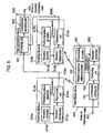
- FIG. 6 shows a structure of a transmission and reception system of the sixth exemplary embodiment.
- a space diversity reception system comprises a transmission device 600 for transmitting a signal, and two units of receiving devices 610a and 610b for performing a process of receiving and demodulating the signal.
- the transmission device 600 is provided with a transmission controller 601 and a modulator / transmitter 602 in place of the diversity transmission timing controller 104 and the time-diversity modulator / transmitter 105 in the transmission device 100 of Figs. 1A and 1B.
- an operation is carried out in the same manner as the transmission device 100 of the first exemplary embodiment between a process of convolution-coding the series of information data being transmitted and a process of puncturing them into two different series of punctured data by using two different puncturing patterns A, 102a, and B, 102b shown in Fig. 1B.
- the modulator / transmitter 602 modulates and transmits one of the two different series of punctured data obtained with the puncturing pattern A, 102a, of Fig. 1B toward the receiving device 610a according to information of a predetermined transmission timing and transmission frequency for the receiving device 610a supplied from the transmission controller 601.
- the modulator / transmitter 602 also modulates and transmits another series of data punctured with the puncturing pattern B, 102b, of Fig. 1B toward the receiving device 610b according to the information of a predetermined transmission timing and transmission frequency for the reception device 610b supplied from the transmission controller 601.
- An arrangement is made in advance so that the transmission timings set for the two series of punctured data do not overlap with each other, and the transmission frequencies are approximately same.
- the two units ofreceiving devices 610a and 610b receive and demodulate the signals transmitted to them from the transmission device 600 according to the information for transmission timings and transmission frequencies supplied by their respective reception controllers 611a and 611b, and output respective series of demodulated data.
- a depuncturing unit 614a depunctures the series of demodulated data by using the puncturing pattern A, 102a, supplied from a puncturing pattern generator 613a, and outputs a series of depunctured data 633a.
- a depuncturing unit 614b depunctures the series of demodulated data by using the puncturing pattern B, 102b, supplied from a puncturing pattern generator 613b, and outputs a series of depunctured data 633b.
- An output processing device 620 accumulates the series of depunctured data 633a and 633b supplied from both of the receiving devices, and a combining unit 621 compounds them symbol by symbol in a unit of block. Then, a convolutional decoding unit 622 convolution-decodes the combined result, and outputs a series of decoded information data 632.
- the foregoing exemplary embodiment of the present invention punctures and convolution-codes a series of information data with different puncturing patterns for every transmission to the individual receiving devices when transmitting identical series of information data to the plurality of the receiving devices, thereby enabling the system to vary puncturing locations for every transmission to the individual receiving devices, prevent a degradation in likelihood of certain information data, and further improve quality of communication.
- the transmission controller 601 in the present exemplary embodiment is so arranged in advance that transmission frequencies to the individual receiving devices are approximately equal, and their transmission timings do not overlap with each other, these are not restrictive. Instead, the transmission frequencies to the individual receiving devices may be arranged so as not to overlap between the transmissions, while maintaining the transmission timings approximately equal. Or, both of the transmission timings and the transmission frequencies can be arranged not to overlap between the transmissions to the receiving devices. In these cases, information for reception timings and receiving frequencies are to be set with the reception controllers 611a and 611b in the individual receiving devices according to information of the transmission side.
- the transmission devices may be provided with a code-division multiplex signal transmitter, instead of the modulator / transmitters 602, for modulating and transmitting the plurality of punctured data series with code-division multiplexing, while maintaining the transmission timings and the transmission frequencies of the transmission controller 601 approximately equal.
- each of the receiving devices may comprise a code-division multiplex signal receiver, instead of the receiver / demodulators 612a and 612b, for outputting series of demodulated data by receiving and demodulating a specific signal addressed to the individual receiving devices out of the signals transmitted with code-division multiplexing from the transmission device by way of extracting it with the despreading process, while setting the reception timings and the receiving frequencies approximately equal between the reception controllers 611a and 611b.
- the system can be constituted with a transmission device for transmitting identical series of information data by code-division multiplexing to a plurality of receiving devices, and the receiving devices for receiving and demodulating the code-division multiplexed signals.
- each receiving device may be provided with a reception level measuring unit for measuring individual signal levels received by the receiver / demodulator 612a or 612b according to information for the reception timing and the reception frequency supplied by the reception controller 611a or 611b, and outputting a result of the measurements.
- the output processing device 620 may be provided with a weighting / combining unit, instead of the combining unit 621, for weighting and compounding the individual series of depunctured data based on the signal reception levels supplied by the individual receiving devices in order to gain an effectiveness equivalent to the maximum-ratio combine diversity, in the same manner as the third exemplary embodiment.
- the system of the described embodiment is provided with two receiving devices, this is not exclusive and three or more receiving devices may be provided, if puncturing patterns to be used for puncturing during transmission to the individual receiving devices are generated in different varieties, and a multiple puncturing pattern generator in the transmission device is adapted to generate every one of these patterns.
- a seventh exemplary embodiment relates to a satellite-path diversity transmission and reception system, in which a transmission device transmits the above-described plurality of different series of punctured data via a plurality of paths with same carrier wave but different in time, and a receiving device receives them via a plurality of satellite repeater stations.
- Fig. 7 shows a structure of a satellite-path diversity transmission and reception system of the seventh exemplary embodiment.
- Satellite repeater stations 700a and 700b relay transmission signals from an earth station transmission device 710 to an earth station receiving device 720.
- the earth station transmission device 710 is provided with an earth station modulator / transmitter 711 in place of the diversity transmission timing controller 104 and the time-diversity modulator / transmitter 105 in the transmission device100 of Figs. 1A and 1B. All other structure and operation remain same as the transmission device 100 of Figs. 1A and 1B.
- the earth station receiving device 720 is provided with an earth station receiver / demodulator 721 in place of the diversity reception timing controller 111 and the time-diversity receiver / demodulator 112 in the receiving device110 of Figs. 1A and 1B. All other structure and operation remain same as the receiving device 110 of Figs. 1 A and 1B.
- a convolutional coding unit 101 convolution-codes identical series of information data at first.
- a puncturing unit 103 punctures the series of obtained convolution-coded data by using each of two forms of puncturing patterns A, 102a, and B, 102b, shown in Fig. 1B, supplied from a multiple puncturing pattern generator 102, and outputs two series of punctured data.
- the earth station modulator / transmitter 711 modulates and transmits a series of data punctured with the puncturing pattern A, 102a, out of the two series of punctured data supplied from the puncturing unit 103 toward the satellite repeater station 700a.
- the earth station modulator / transmitter 711 also modulates and transmits another series of data punctured with the puncturing pattern B, 102b, toward the satellite repeater station 700b.
- the earth station receiver / demodulator 721 in the earth station receiving device 720 receives and demodulates individual transmission signals relayed via the satellite repeater stations 700a and 700b, and outputs two varieties of demodulated data series.
- a depuncturing unit 114 depunctures the series of demodulated data derived from a signal of the satellite repeater station 700a, out of the two series of demodulated data supplied from the earth station receiver / demodulator 721, by using a puncturing pattern, which is identical to the puncturing pattern A, 102a, supplied by a multiple puncturing pattern generator 113.
- the depuncturing unit 114 also depunctures another series of demodulated data derived from a signal of the satellite repeater station 700b by using a puncturing pattern that is identical to the puncturing pattern B, 102b, supplied by the multiple puncturing pattern generator 113.
- a combining unit 115 compounds the two varieties of depunctured data series obtained here from symbol to symbol in a unit of block. Then, a convolutional decoding unit 116 convolution-decodes the combined result, and outputs a series of decoded information data 732.
- the earth station transmission device punctures identical series of information data by using a plurality of different puncturing patterns, and executes a satellite-path diversity transmission of the different series of obtained punctured data to a plurality of satellites as transmission data for individual satellite-path diversity branches.
- the earth station receiving device depunctures the transmission data by using a plurality of different puncturing patterns, which are identical to those of the transmission side, compounds and convolution-decodes thereafter.
- the invention is able to avoid a degradation in likelihood of certain information data, and to further improve quality of the communication.
- each of the earth stations may comprise both of an earth station transmission device 710 and an earth station receiving device 720.
- system of the described embodiment is adapted to use two satellite repeater stations, this is not exclusive and three or more repeater stations can be used as is evident from the other exemplary embodiments.
- first, fourth, fifth and sixth exemplary embodiments are systems that make one-way communication from transmission devices to receiving devices, they can be systems that make bi-directional communication between two transmission / reception devices having a combined function of both transmission device and receiving device and sharing common functional components between them.
- the transmission device in each of the foregoing exemplary embodiments has been described as having a (multiple) puncturing pattern generator and a puncturing unit as separate blocks, they can be combined into one block.
- the puncturing unit may be adapted to generate a (or plural forms of) puncturing pattern(s), and carry out puncturing also.
- the receiving device has been described as having a (multiple) puncturing pattern generator and a depuncturing unit as separate blocks, they can be combined also into one block.
- the depuncturing unit may be adapted to generate a (or plural forms of) puncturing pattern(s) identical to the (plural forms of) puncturing pattern(s) generated by the (multiple) puncturing pattern generator of the transmission device, and carry out depuncturing.
- a system of the present invention convolution-codes series of information data by using puncturing patterns, which differ from one diversity branch to another, when transmitting and receiving primarily the series of information data with a combination of punctured-convolution-coding and diversity, thereby preventing a degradation in likelihood of certain information data, and achieving a remarkable improvement in quality of communication.
Landscapes
- Engineering & Computer Science (AREA)
- Computer Networks & Wireless Communication (AREA)
- Signal Processing (AREA)
- Error Detection And Correction (AREA)
- Detection And Prevention Of Errors In Transmission (AREA)
- Radio Transmission System (AREA)
Claims (19)
- Empfänger, der umfasst:dadurch gekennzeichnet, dass er des Weiteren umfasst:eine Empfangs-/Demodulationseinrichtung (112), die ein Signal empfängt und demoduliert, das von einer Sendequelle (100) über ein Kommunikationssignal gesendet wird, und eine Vielzahl demodulierter Datenreihen (127a, 127b) ausgibt;eine Depunktiereinrichtung (114), die die Vielzahl demodulierter Datenreihen (127a, 127b) unter Verwendung von Punktiermustern (102a, 102b), die identisch mit denen sind, die durch die Sendequelle (100) verwendet werden, einzeln depunktiert und eine Vielzahl depunktierter Datenreihen (128a, 128b) ausgibt;eine Kombiniereinrichtung (115), die die Vielzahl depunktierter Datenreihen (128a, 128b) kombiniert und ein Kombinationsergebnis ausgibt;eine Faltungsdecodiereinrichtung (116), die das Kombinationsergebnis decodiert und decodierte Daten (122) ausgibt;wobei die Kombiniereinrichtung (302) des Weiteren eine Wichtungseinrichtung umfasst, die die Vielzahl depunktierter Datenreihen (128a, 128b) entsprechend der gespeicherten Messergebnisse (R1, R2) wichtet, bevor sie diese kombiniert.eine Empfangspegel-Speichereinrichtung (301), die einen Empfangspegel für jede der gesendeten Vielzahl punktierter Datenreihen (126a, 126b), die von der Empfangs-/Demodulationseinrichtung (112) empfangen werden, misst und ein Ergebnis (R1, R2) der Messung speichert; und
- Sende-und-Empfangs-System, das einen Sender (100), einen Empfänger (110, 310) und einen Kommunikationskanal zwischen dem Sender und dem Empfänger umfasst,
wobei der Sender (100) umfasst:wobei der Empfänger (110, 310) umfasst:eine Faltungscodiereinrichtung (101), die Faltungscodierung einer Reihe von Eingabedaten (121) durchführt und eine faltungscodierte Datenreihe (125) ausgibt,eine Punktiereinrichtung (103), die die faltungscodierten Datenreihen (125) unter Verwendung einer Vielzahl von Punktiermustern (120a, 102 b) einzeln punktiert und eine Vielzahl punktierter Datenreihen (126a, 126b) ausgibt;eine Modulations-/Sendeeinrichtung (105), die die Vielzahl punktierter Datenreihen (126a, 126b) moduliert und sendet,gekennzeichnet durch:eine Empfangs-/Demodulationseinrichtung (112), die die Vielzahl gesendeter punktierter Datenreihen empfängt und demoduliert und eine Vielzahl demodulierter Datenreihen (127a, 127b) ausgibt;eine Depunktiereinrichtung (114), die die Vielzahl demodulierter Datenreihen (127a, 127b) unter Verwendung von Punktiermustern (102a, 102b), die identisch mit denen sind, die durch die Sendequelle (100) verwendet werden, einzeln depunktiert und eine Vielzahl depunktierter Datenreihen (128a, 128b) ausgibt;eine Kombiniereinrichtung (115), die die Vielzahl depunktierter Datenreihen (128a, 128b) kombiniert und ein Kombinationsergebnis ausgibt;eine Faltungsdecodiereinrichtung (116), die das Kombinationsergebnis decodiert und decodierte Daten (122) ausgibt;wobei die Kombiniereinrichtung (115) des Weiteren eine Wichtungseinrichtung umfasst, die die Vielzahl depunktierter Datenreihen (128a, 128b) entsprechend der gespeicherten Messergebnisse (R1, R2) wichtet, bevor sie diese kombiniert.eine Empfangspegel-Speichereinrichtung (301), die einen Empfangspegel für jede der gesendeten Vielzahl punktierter Datenreihen (126a, 126b), die von der Empfangs-/Demodulationseinrichtung (112) empfangen werden, misst und ein Ergebnis der Messung speichert; und - Sende-und-Empfangs-System nach Anspruch 2, dadurch gekennzeichnet, dass:wobei die Empfangs-/Demodulationseinrichtung (112) die gesendete Vielzahl punktierter Daten über den wenigstens einen Kommunikationssignal empfängt.die Modulations-/Sendeeinrichtung (105) die Vielzahl punktierter Datenreihen (126a, 126b) über wenigstens einen Kommunikationssignal sendet;
- Sende-und-Empfangs-System nach Anspruch 2 oder 3, dadurch gekennzeichnet, dass:wobei der Sender (100) dadurch gekennzeichnet ist, dass:der Sender (100) des Weiteren umfasst:mehrere Punktiermuster-Erzeugungseinrichtungen (102), die eine vorgegebene Vielzahl von Punktiermustern (102a, 102b) erzeugen, die eine identische Punktierrate haben, sich jedoch hinsichtlich ihrer Blockmuster unterscheiden;eine Diversitysende-Zeitsteuereinrichtung (104), die ein Diversitysende-Zeitsteuersignal (123) ausgibt, um ein Diversitysenden in vorgegebenen Zeitintervallen auszuführen;wobei der Empfänger (110, 310) des Weiteren umfasst:die Punktiereinrichtung (103) jedes der Vielzahl von Punktiermustern (102a, 102b) verwendet, um die faltungscodierten Datenreihen (125) zu punktieren;die Modulations-/Sendeeinrichtung (105) eine Zeitdiversity-Modulations-/Sendeeinrichtung (105) ist, die in Reaktion auf das Diversitysende-/Zeitsteuersignal (123) die Vielzahl punktierter Datenreihen (126a, 126b) nacheinander als Zeitdiversity-Sendedaten moduliert und sendet;wobei der Empfänger (110, 310) dadurch gekennzeichnet ist, dass:eine Diversityempfangs-Zeitsteuereinrichtung (111), die ein vorgegebenes Diversityempfangs-Zeitsteuersignal ausgibt, um Empfang eines Zeitdiversity-Sendesignals des Senders in den vorgegebenen Intervallen auszuführen;mehrere Punktiermuster-Erzeugungseinrichtung (113), die Punktiermuster (102a, 102b) erzeugen, die mit der vorgegebenen Vielzahl von Punktiermustern (102a, 102b) des Empfängers (100) identisch sind;die Empfangs-/Demodulationseinrichtung ( 112) eine Zeitdiversity-Empfangs-/Demodulationseinrichtung (112) ist, die das Zeitdiversity-Sendesignal des Senders empfängt und demoduliert;die Depunktiereinrichtung (114) jede der Vielzahl punktierter Datenreihen (126a, 126b), die durch die Zeitdiversity-Empfangs-/Demodulationseinrichtung (112) empfangen und demoduliert werden, unter Verwendung der Vielzahl von Punktiermustern (102a, 102b), die durch die mehreren Punktiermuster-Erzeugungseinrichtungen (113) des Empfängers zugeführt werden, depunktiert.
- Sende-und-Empfangs-System nach Anspruch 4, dadurch gekennzeichnet, dass:die demodulierte Datenreihen (127a, 127b), die von der Zeitdiversity-Empfangs/Demodulationseinrichtung (112) ausgegeben werden, digitale Werte sind, die mit einer vorgegebenen Anzahl von Bits quantisiert sind;bei dem Depunktiervorgang, der durch die erste Depunktiereinrichtung (114) ausgeführt wird, ein mittlerer Wert zwischen zwei digitale Werte eingefügt wird, die einem einem Zeichen und einer Leerstelle entsprechen;bei dem Kombiniervorgang, der durch die Kombiniereinrichtung (115) ausgeführt wird, zu jedem Symbol in einer Blockeinheit der Vielzahl depunktierter Datenserien (128a, 128b) ein digitaler Wert hinzugefügt wird, unddie Faltungsdecodiereinrichtung (116) eine Viterbi-Weichquantifizierungseinrichtung zum Durchführen von Viterbi-Weichentscheidung enthält.
- Sende-und-Empfangs-System nach Anspruch 4 oder 5, dadurch gekennzeichnet, dass Punktierpositionen in der vorgegebenen Vielzahl von Punktiermustem (102a, 102b) im Voraus so festgelegt werden, dass sich die Punktierpositionen in der Vielzahl von Mustern nicht überlappen.
- Sende-und-Empfangs-System nach einem der Ansprüche 4 bis 6, dadurch gekennzeichnet, dass die mehreren Punktiermuster-Erzeugungseinrichtungen (112, 113) in dem Empfänger und dem Sender jeweils umfassen:eine Bezugsmatrix-Erzeugungseinrichtung (201), die eine Bezugsmatrix von Punktiermustern (102a, 102b) erzeugt, undeine Matrix-Umwandlungseinrichtung (202), die ein anderes Punktiermuster für jeden Diversityzweig ausgibt, in dem sie eine oder mehrere Reihen, Spalten und Elemente der Bezugsmatrix umwandelt.
- Sende-und-Empfangs-System nach einem der Ansprüche 3 bis 7, dadurch gekennzeichnet, dass:der Sender (400) mehrere Punktiermuster-Erzeugungseinrichtungen (102) umfasst, die eine vorgegebene Vielzahl von Punktiermustern (102a, 102b) erzeugen, die eine identische Punktierrate haben, sich jedoch hinsichtlich ihrer Blockmuster unterscheiden;die Modulier-/Sendeeinrichtung (105) eine Codemultiplex-Signalsendeeinrichtung (401) ist, die die Vielzahl punktierter Datenreihen (126a, 126b) sendet und diese gleichzeitig sendet;der Empfänger (410) mehrere Punktiermuster-Erzeugungseinrichtungen (113) umfasst, die eine vorgegebene Vielzahl von Punktiermustern (102a, 102b) erzeugen, die mit der Vielzahl von Punktiermustern (102a, 102b) identisch sind, die durch die mehreren Punktiermuster-Erzeugungseinrichtungen (102) des Senders (400) erzeugt werden; unddie Empfangs-/Demoduliereinrichtung (112) eine Codemultiplex-Signalempfangseinrichtung (402) ist, die die Vielzahl gesendeter punktierter Datenreihen empfängt und demoduliert und eine Vielzahl demodulierter Datenreihen (127a, 127b) ausgibt.
- Sende-und-Empfangs-System nach einem der Ansprüche 4 bis 8, dadurch gekennzeichnet, dass:der Sender eine Sende-Erdstation (710) eines Satellitenkanal-Sender-Empfänger-Systems ist;der Empfänger eine Empfangs-Erdstation (720) eines Satelliten-Sender-Empfänger-Systems ist; unddas Sende-und-Empfangs-System des Weiteren eine Vielzahl von Zwischenverstärkerstationen (700a, 700b) umfasst, die die faltungscodierten und punktierten Datenreihen empfangen, die von einer Sende-Erdstation (710) gesendet werden, und die faltungscodierten und punktierten Datenreihen zu der Empfangs-Erdstation (720) weiterleiten.
- Sende-und-Empfangs-System nach einem der Ansprüche 3 bis 9, dadurch gekennzeichnet, dass:das Sende-und-Empfangs-System eine Vielzahl von Erdstationen (710, 720) umfasst, die miteinander über die Vielzahl von Satelliten-Zwischenverstärkerstationen (700a, 700b) kommunizieren, wobei jede Erdstation eine Sende-Erdstation und eine Empfangs-Erdstation umfasst.
- Sende-und-Empfangs-System, das eine Vielzahl von Sendern (500a, 500b), die Reihen identischer Informationsdaten (521 ) senden, und einen Empfänger (510), der eine Vielzahl von Signalen empfängt, die von den Sendern (500a, 500b) gesendet werden, umfasst, wobei jeder der Vielzahl von Sendern umfasst:wobei der Empfänger (510) umfasst:eine Faltungscodiereinrichtung (501 a, 501 b), die Faltungscodierung der Reihe identischer Informationseingabedaten (521 ) durchführt und sie ausgibt;eine Punktiermuster-Erzeugungseinrichtung (502a, 502b), die ein Punktiermuster erzeugt;eine Punktiereinrichtung (503a, 503b), die eine faltungscodierte Datenreihe (125), die von der Faltungscodiereinrichtung (501 a, 501 b) ausgegeben wird, unter Verwendung des Punktiermusters von der Punktiermuster-Erzeugungseinrichtung (502a, 502b) punktiert und eine punktierte Datenreihe ausgibt;eine Sendesteuereinrichtung (504a, 504b), die eine vorgegebene Sendezeit und eine vorgegebene Sendefrequenz an den Sender ausgibt, um ein Senden zu steuern; undeine erste Modulations-/Sendeeinrichtung (505a, 505b), die in Reaktion auf die Sendezeit und die Sendefrequenz die punktierte Datenreihe moduliert und sendet;dadurch gekennzeichnet, dass:eine Sendesteuereinrichtung (511), die eine vorgegebene Empfangszeit und eine vorgegebene Empfangsfrequenz ausgibt, um einen Empfangsvorgang zu steuern;eine Empfangs-/Demodulationseinrichtung (512), die in Reaktion auf die vorgegebene Empfangszeit und die vorgegebene Empfangsfrequenz die Vielzahl punktierter Datenreihen (126a, 126b) der Vielzahl von Sendern empfängt und demoduliert und einzelne demodulierte Datenreihen (127a, 127b) ausgibt;mehrere Punktiermuster-Erzeugungseinrichtungen (113), die eine Vielzahl von Punktiermustern (102a, 102b) erzeugen;eine Depunktiereinrichtung (114), die jede der demodulierten Datenreihen (127a, 127b) depunktiert und einzelne depunktierte Datenreihen (128a. 129b) ausgibt;eine Kombiniereinrichtung (115), die jedes Symbol in einer Blockeinheit der mehreren Datenreihen (128a, 128b) kombiniert und ein Kombinationsergebnis ausgibt; undeine Faltungsdecodiereinrichtung (116), die Faltungsdecodierung des Kombinationsergebnisses durchführt,die erzeugten Punktiermuster (102a, 102b), die durch die Punktiermuster-Erzeugungseinrichtungen (502a, 502b) der Vielzahl von Sendern erzeugt werden, eine identische Punktierrate haben, sich jedoch hinsichtlich ihrer Blockmuster unterscheiden;die Empfangssteuereinrichtung (511) den Empfang der Vielzahl punktierter Datenreihen (126a, 126b) steuert, die durch die Vielzahl von Sendern gesendet werden;die Empfangs-/Demodulationseinrichtung (512), die Vielzahl punktierter Datenreihen (126a, 126b), die durch jeden der Sender gesendet werden, empfängt und demoduliert;die Punktiermuster (102a, 102b), die durch die mehreren Punktiermuster-Erzeugungseinrichtungen (113) des Empfängers erzeugt werden, mit den einzelnen Punktiermustern (102a, 102b) der Vielzahl von Sendern (500a, 500b) identisch sind;die Depunktiereinrichtung (114) jede der demodulierten Datenreihen (127a, 127b) unter Verwendung eines Punktiermusters depunktiert, das mit dem identisch ist, das durch den entsprechenden Sender zum Punktieren der entsprechenden Daten verwendet wird; unddas Sende-und-Empfangs-System die Sendefrequenzen annähernd gleich einstellt und die Sendezeiten im Voraus so auswählt, dass die Sendezeiten der Vielzahl von Sendern einander nicht überlappen, und jeder Sender die faltungscodierten und mit verschiedenen Punktiermustern (102a, 102b) punktierten Reihen identischer Informationsdaten zu einer anderen Zeit sendet.
- Sende-und-Empfangs-System nach Anspruch 9, dadurch gekennzeichnet, dass:die Sendesteuereinrichtung (504a, 504b) Sendezeiten annähernd gleich einstellt und die Sendefrequenzen im Voraus so auswählt, dass die Sendefrequenzen der Vielzahl der Sender einander nicht überlappen; unddie Empfangssteuereinrichtung (511) Empfangszeiten und Empfangsfrequenzen im Voraus einstellt, so dass sie den Sendezeiten und den Sendefrequenzen der Vielzahl von Sendern entsprechen.
- Sende-und-Empfangs-System nach Anspruch 9, dadurch gekennzeichnet, dass:die Sendesteuereinrichtung (504a, 504b) Sendezeiten und Sendefrequenzen im Voraus so einstellt, dass die Sendezeiten und die Sendefrequenzen der Vielzahl von Sendern einander nicht überlappen; unddie Empfangssteuereinrichtung (511) Empfangszeiten und Empfangsfrequenzen im Voraus so einstellt, dass sie den Sendezeiten und den Sendefrequenzen der Sendesteuereinrichtung entsprechen.
- Sende-und-Empfangs-System nach Anspruch 11, wobei:die Sendesteuereinrichtung (504a, 504b) Sendezeiten und Sendefrequenzen im Voraus einstellt, so dass sie einander unter der Vielzahl von Sendern gleich sind;die Modulations-/Sendeeinrichtung (505a, 505b) eine Codemultiplex-Signalsendeeinrichtung ist, die die Vielzahl punktierter Datenreihen (126a, 126b) sendet;die Empfangssteuereinrichtung (511) in der Empfangsvorrichtung Empfangszeiten und Empfangsfrequenzen im Voraus einstellt, so dass sie den Sendezeiten und den Sendefrequenzen der Sendesteuereinrichtung entsprechen; unddie Empfangs-/Demodulationseinrichtung (512) eine Codemultiplex-Signalempfangseinrichtung ist, die die gesendeten faltungscodierten und mit verschiedenen Punktiermustern (102a, 102b) punktierten Reihen identischer Informationsdaten empfängt und demoduliert und eine Vielzahl demodulierter Datenreihen (127a, 127b) ausgibt.
- Sende-und-Empfangs-System, das einen Sender (600), eine Vielzahl von Empfängern (610a, 610b), die ein von dem Sender ausgegebenes Signal empfangen, umfasst,
wobei der Sender (600) umfasst:wobei jeder der Vielzahl von Empfängern (610a, 610b) umfasst:eine Faltungscodiereinrichtung (101), die ei ne Reihe von Eingabedaten (631) ausgibt, indem sie Faltungscodierung der Reihe von Daten durchführt;mehrere Punktiermuster-Erzeugungseinrichtungen (102), die eine vorgegebene Vielzahl von Punktiermustern (102a, 102b) erzeugen und ausgeben, die eine identische Punktierrate haben, sich jedoch hinsichtlich ihres Blockmusters unterscheiden;eine Punktiereinrichtung (103), die die faltungscodierten Datenreihen (125) unter Verwendung jedes der vorgegebenen Vielzahl von Punktiermustern (102a, 102b) punktiert und eine vorgegebene Vielzahl verschiedener punktierter Datenreihen ausgibt;eine Sendesteuereinrichtung (601), die eine vorgegebene Sendezeit und eine vorgegebene Sendefrequenz für den Sender ausgibt; undeine Modulations-/Sendeeinrichtung (602), die in Reaktion auf die Sendezeit und die Sendefrequenz jede der Vielzahl verschiedener punktierter Datenreihen moduliert und sendet,dadurch gekennzeichnet, dass:eine Empfangssteuereinrichtung (611a, 611 b), die eine vorgegebene Sendezeit und eine vorgegebene Sendefrequenz ausgibt, um einen Empfangsvorgang zu steuern;eine Empfangs-/Demodulationseinrichtung (612a, 612b), die eine gesendete punktierte Datenreihe entsprechend der vorgegebenen Empfangszeit und der vorgegebenen Empfangsfrequenz empfängt und demoduliert und eine demodulierte Datenreihe ausgibt;eine Punktiermuster-Erzeugungseinrichtung (613a, 613b), die ein Punktiermuster erzeugt; undeine Depunktiereinrichtung (614a, 614b), die die demodulierte Datenreihe unter Verwendung des Punktiermusters, das von der Punktiermuster-Erzeugungseinrichtung (613a, 613b) zugeführt wird, depu nktiert und eine depunktierte Datenreihe (128a, 128b) ausgibt, unddie Punktiermuster-Erzeugungseinrichtungen (613a, 613b) in der Vielzahl von Empfängern (610a, 610b) ein Punktiermuster erzeugen, das mit dem Punktiermuster identisch ist, das verwendet wird, um die punktierte Datenreihe zu punktieren, die der jeweilige Empfänger empfängt;die Sendezeit in dem Sender (600) so ist, dass sich die einzelnen Sendevorgänge der einzelnen punktierten Datenreihen nicht überlappen, unddie Sendefrequenz in dem Sender unter den einzelnen Sendevorgängen annähernd gleich ist,das Sende-und-Empfangs-System des Weiteren eine Ausgabe-Verarbeitungseinrichtung (620) umfasst, die Reihen von Daten, die in der Vielzahl von Empfängern empfangen werden, akkumuliert, wobei die Ausgabe-Verarbeitungsvorrichtung umfasst:eine Kombiniereinrichtung (621), die jedes Symbol in einer Blockeinheit in der depunktierten Datenreihe (633a, 633b), die von jedem der Vielzahl von Empfängern gewonnen wird, kombiniert und ein Kombinationsergebnis ausgibt,eine Faltungsdecodiereinrichtung (622), die Faltungsdecodierung des Kombinationsergebnisses durchführt. - Sende-und-Empfangs-System nach Anspruch 13, dadurch gekennzeichnet, dass:die Sendesteuereinrichtung (601 ) die einzelnen Sendezeiten annähernd gleich einstellt und die Sendefrequenzen im Voraus so auswählt, dass sich die Sendefrequenzen nicht überlappen; unddie Empfangssteuereinrichtung (611 a, 611 b) Empfangszeiten und Empfangsfrequenzen für jeden Empfänger (610a, 610b im Voraus so einstellt, dass sie den Sendezeiten und den Sendefrequenzen der Sendesteuereinrichtung (601) entsprechen.
- Sende-und-Empfangs-System nach Anspruch 13, dadurch gekennzeichnet, dass:die Sendesteuereinrichtung (601) Sendezeiten und Sendefrequenzen im Voraus so einstellt, dass sich die Sendezeiten und die Sendefrequenzen nicht überlappen; unddie Empfangssteuereinrichtung (611a, 611b) Empfangszeiten und Empfangsfrequenzen für jeden Empfänger im Voraus so einstellt, dass sie den Sendezeiten und den Sendefrequenzen der Sendesteuereinrichtungen (601) entsprechen.
- Sende-und-Empfangs-System nach Anspruch 15, dadurch gekennzeichnet, dass:die Sendesteuereinrichtung (601) Sendezeiten und Sendefrequenzen im Voraus so einstellt, dass sie annähernd gleich sind;die Modulations-/Sendeeinrichtung (602) eine Codemultiplex-Signalsendeeinrichtung ist, die die Vielzahl punktierter Datenreihen (126a, 126b) sendet;die Empfangssteuereinrichtung (611a, 611b) in der Empfangsvorrichtung Empfangszeiten und Empfangsfrequenzen für jeden Empfänger im Voraus so einstellt, dass sie den Sendezeiten und den Sendefrequenzen der Sendesteuereinrichtung (601) entsprechen; unddie Empfangs-/Demoduliereinrichtung (612a, 612b) eine Codemultiplex-Signalempfangsvorrichtung ist, die die gesendeten faltungscodierten und mit verschiedenen Punktiermustern (102a, 102b) punktierten Reihen identischer Informationsdaten empfängt und demoduliert und eine Vielzahl demodulierter Datenreihen ausgibt.
- Verfahren zum Empfangen, das die folgenden Schritte umfasst:dadurch gekennzeichnet, dass:Empfangen und Demodulieren eines Signals, das über einen Kommunikationskanal gesendet wird, und Ausgeben einer Vielzahl demodulierter Datenreihen (127a, 127b);Depunktieren der Vielzahl demodulierter Datenreihen (127a, 127b) unter Verwendung von Punktiermustern (102a, 102b), die mit der Vielzahl von Punktiermustern (102a, 102b) identisch sind, die beim Schritt des Punktierens verwendet werden, und Ausgeben einer Vielzahl depunktierter Datenreihen (128a, 128b);Kombinieren der Vielzahl depunktierter Datenreihen (128a, 128b) und Ausgeben eines Kombinationsergebnisses; undFaltungscodieren des Kombinationsergebnisses und Ausgeben decodierter Daten (122),der Schritt des Kombinierens den Schritt des Wichtens einschließt, bei dem jede der gesendeten Vielzahl punktierter Datenreihen (128a, 128b) entsprechend dem Empfangspegel jeder der gesendeten Vielzahl punktierter Datenreihen (126a, 126b) gewichtet wird, bevor die Vielzahl depunktierter Datenreihen (128a, 128b) kombiniert werden.
Applications Claiming Priority (2)
| Application Number | Priority Date | Filing Date | Title |
|---|---|---|---|
| JP10167868A JP2000004215A (ja) | 1998-06-16 | 1998-06-16 | 送受信システム |
| JP16786898 | 1998-06-16 |
Publications (3)
| Publication Number | Publication Date |
|---|---|
| EP0966124A2 EP0966124A2 (de) | 1999-12-22 |
| EP0966124A3 EP0966124A3 (de) | 2002-05-15 |
| EP0966124B1 true EP0966124B1 (de) | 2003-12-17 |
Family
ID=15857581
Family Applications (1)
| Application Number | Title | Priority Date | Filing Date |
|---|---|---|---|
| EP99111667A Expired - Lifetime EP0966124B1 (de) | 1998-06-16 | 1999-06-16 | Verfahren und Einrichtung zum Senden und Empfangen von punktierten, faltungskodierten Daten |
Country Status (4)
| Country | Link |
|---|---|
| US (2) | US6693889B1 (de) |
| EP (1) | EP0966124B1 (de) |
| JP (1) | JP2000004215A (de) |
| DE (1) | DE69913608T2 (de) |
Families Citing this family (76)
| Publication number | Priority date | Publication date | Assignee | Title |
|---|---|---|---|---|
| FI109251B (fi) | 1999-09-10 | 2002-06-14 | Nokia Corp | Tiedonsiirtomenetelmä, radiojärjestelmä, radiolähetin ja radiovastaanotin |
| DE19956492A1 (de) * | 1999-11-24 | 2001-05-31 | Siemens Ag | Verfahren zum Abbilden von Formatkennungs-Bits auf einen in einem Komprimiermodus zu sendenden Rahmen |
| JP3450788B2 (ja) * | 2000-03-06 | 2003-09-29 | 松下電器産業株式会社 | 復号化装置および復号化処理方法 |
| EP1277287A4 (de) * | 2000-04-21 | 2004-03-03 | Samsung Electronics Co Ltd | Vorrichtung und verfahren zur flexiblen datenratenanpassung in einem datenkommunikationssystem |
| US6728323B1 (en) * | 2000-07-10 | 2004-04-27 | Ericsson Inc. | Baseband processors, mobile terminals, base stations and methods and systems for decoding a punctured coded received signal using estimates of punctured bits |
| JP4213879B2 (ja) * | 2000-07-11 | 2009-01-21 | エルジー エレクトロニクス インコーポレイティド | 通信システム及び該システムの信号伝送方法 |
| KR100339343B1 (ko) * | 2000-07-11 | 2002-06-03 | 서평원 | 통신 시스템 및 이 시스템의 신호 처리 방법 |
| US7068619B2 (en) * | 2000-08-07 | 2006-06-27 | Lucent Technologies Inc. | Radio link control with limited retransmissions for streaming services |
| US7095808B1 (en) * | 2000-08-16 | 2006-08-22 | Broadcom Corporation | Code puncturing method and apparatus |
| US20020181439A1 (en) * | 2000-08-30 | 2002-12-05 | Masayuki Orihashi | Data transmitting apparatus, radio communication system and radio communication method |
| US7295509B2 (en) * | 2000-09-13 | 2007-11-13 | Qualcomm, Incorporated | Signaling method in an OFDM multiple access system |
| US9130810B2 (en) | 2000-09-13 | 2015-09-08 | Qualcomm Incorporated | OFDM communications methods and apparatus |
| WO2002032016A1 (en) * | 2000-10-09 | 2002-04-18 | Samsung Electronics Co., Ltd. | Apparatus and method for coding/decoding tfci bits in an asynchronous cdma communicaiton system |
| DE10051243A1 (de) * | 2000-10-17 | 2002-04-25 | Philips Corp Intellectual Pty | Verfahren zum Auswählen (puncturing) von Datenbits |
| US7034893B2 (en) * | 2001-03-30 | 2006-04-25 | Broadcom Corporation | Method and apparatus for reception of terrestrial digital television signals |
| JP4634672B2 (ja) | 2001-09-25 | 2011-02-16 | 三菱電機株式会社 | サイトダイバーシチ送受信装置 |
| EP1458203A4 (de) * | 2001-12-21 | 2005-08-03 | Mitsubishi Electric Corp | Funkkommunikationssystem und -sender |
| US8078808B2 (en) | 2002-04-29 | 2011-12-13 | Infineon Technologies Ag | Method and device for managing a memory for buffer-storing data blocks in ARQ transmission systems |
| KR100539854B1 (ko) | 2003-01-09 | 2005-12-28 | 삼성전자주식회사 | 시공간 트렐리스 코드를 사용하는 이동 통신 시스템에서다중화 이득과 다이버시티 이득을 동시에 획득하기 위한데이터 송수신 장치 및 방법 |
| EP1445885B1 (de) * | 2003-02-05 | 2008-03-05 | Broadcom Corporation | Verfahren und Gerät zur Punktierung von Kodesymbolen |
| US7430241B2 (en) | 2003-03-14 | 2008-09-30 | Lucent Technologies Inc. | Method for early decoding of control channel information |
| US7260659B2 (en) * | 2003-06-30 | 2007-08-21 | Intel Corporation | Rate matching apparatus, systems, and methods |
| WO2005041469A1 (en) * | 2003-10-23 | 2005-05-06 | Philips Intellectual Property & Standards Gmbh | Decoding and reconstruction of data |
| US9148256B2 (en) | 2004-07-21 | 2015-09-29 | Qualcomm Incorporated | Performance based rank prediction for MIMO design |
| US9137822B2 (en) | 2004-07-21 | 2015-09-15 | Qualcomm Incorporated | Efficient signaling over access channel |
| JP4949268B2 (ja) * | 2004-12-14 | 2012-06-06 | シリコン ハイブ ビー・ヴィー | プログラム可能な信号及び処理回路及びデパンクチャリング方法 |
| US7953047B2 (en) * | 2005-01-24 | 2011-05-31 | Qualcomm Incorporated | Parser for multiple data streams in a communication system |
| WO2006096689A1 (en) * | 2005-03-08 | 2006-09-14 | Qualcomm Flarion Technologies, Inc. | Methods and apparatus for efficient digital broadcast signaling in a wireless communications system |
| US9246560B2 (en) | 2005-03-10 | 2016-01-26 | Qualcomm Incorporated | Systems and methods for beamforming and rate control in a multi-input multi-output communication systems |
| US9154211B2 (en) | 2005-03-11 | 2015-10-06 | Qualcomm Incorporated | Systems and methods for beamforming feedback in multi antenna communication systems |
| US8446892B2 (en) | 2005-03-16 | 2013-05-21 | Qualcomm Incorporated | Channel structures for a quasi-orthogonal multiple-access communication system |
| US9143305B2 (en) * | 2005-03-17 | 2015-09-22 | Qualcomm Incorporated | Pilot signal transmission for an orthogonal frequency division wireless communication system |
| US9461859B2 (en) | 2005-03-17 | 2016-10-04 | Qualcomm Incorporated | Pilot signal transmission for an orthogonal frequency division wireless communication system |
| US9520972B2 (en) * | 2005-03-17 | 2016-12-13 | Qualcomm Incorporated | Pilot signal transmission for an orthogonal frequency division wireless communication system |
| JP4562575B2 (ja) * | 2005-03-30 | 2010-10-13 | 京セラ株式会社 | 通信システム、通信装置、通信方法及び通信制御プログラム |
| US9184870B2 (en) | 2005-04-01 | 2015-11-10 | Qualcomm Incorporated | Systems and methods for control channel signaling |
| US9036538B2 (en) | 2005-04-19 | 2015-05-19 | Qualcomm Incorporated | Frequency hopping design for single carrier FDMA systems |
| US9408220B2 (en) | 2005-04-19 | 2016-08-02 | Qualcomm Incorporated | Channel quality reporting for adaptive sectorization |
| US8611284B2 (en) | 2005-05-31 | 2013-12-17 | Qualcomm Incorporated | Use of supplemental assignments to decrement resources |
| US8879511B2 (en) * | 2005-10-27 | 2014-11-04 | Qualcomm Incorporated | Assignment acknowledgement for a wireless communication system |
| US8565194B2 (en) | 2005-10-27 | 2013-10-22 | Qualcomm Incorporated | Puncturing signaling channel for a wireless communication system |
| US8462859B2 (en) | 2005-06-01 | 2013-06-11 | Qualcomm Incorporated | Sphere decoding apparatus |
| US9179319B2 (en) | 2005-06-16 | 2015-11-03 | Qualcomm Incorporated | Adaptive sectorization in cellular systems |
| US8599945B2 (en) | 2005-06-16 | 2013-12-03 | Qualcomm Incorporated | Robust rank prediction for a MIMO system |
| US20070025463A1 (en) * | 2005-07-29 | 2007-02-01 | Aldana Carlos H | Bit parser for interleaver in transmitter with multiple transmit antennas |
| US8885628B2 (en) | 2005-08-08 | 2014-11-11 | Qualcomm Incorporated | Code division multiplexing in a single-carrier frequency division multiple access system |
| US9209956B2 (en) | 2005-08-22 | 2015-12-08 | Qualcomm Incorporated | Segment sensitive scheduling |
| US20070041457A1 (en) | 2005-08-22 | 2007-02-22 | Tamer Kadous | Method and apparatus for providing antenna diversity in a wireless communication system |
| US8644292B2 (en) | 2005-08-24 | 2014-02-04 | Qualcomm Incorporated | Varied transmission time intervals for wireless communication system |
| US9136974B2 (en) | 2005-08-30 | 2015-09-15 | Qualcomm Incorporated | Precoding and SDMA support |
| US9088384B2 (en) | 2005-10-27 | 2015-07-21 | Qualcomm Incorporated | Pilot symbol transmission in wireless communication systems |
| US8582509B2 (en) | 2005-10-27 | 2013-11-12 | Qualcomm Incorporated | Scalable frequency band operation in wireless communication systems |
| US9172453B2 (en) | 2005-10-27 | 2015-10-27 | Qualcomm Incorporated | Method and apparatus for pre-coding frequency division duplexing system |
| US8477684B2 (en) | 2005-10-27 | 2013-07-02 | Qualcomm Incorporated | Acknowledgement of control messages in a wireless communication system |
| US8693405B2 (en) | 2005-10-27 | 2014-04-08 | Qualcomm Incorporated | SDMA resource management |
| US9210651B2 (en) | 2005-10-27 | 2015-12-08 | Qualcomm Incorporated | Method and apparatus for bootstraping information in a communication system |
| US9144060B2 (en) | 2005-10-27 | 2015-09-22 | Qualcomm Incorporated | Resource allocation for shared signaling channels |
| US9225416B2 (en) | 2005-10-27 | 2015-12-29 | Qualcomm Incorporated | Varied signaling channels for a reverse link in a wireless communication system |
| US8045512B2 (en) | 2005-10-27 | 2011-10-25 | Qualcomm Incorporated | Scalable frequency band operation in wireless communication systems |
| US9225488B2 (en) | 2005-10-27 | 2015-12-29 | Qualcomm Incorporated | Shared signaling channel |
| US8582548B2 (en) | 2005-11-18 | 2013-11-12 | Qualcomm Incorporated | Frequency division multiple access schemes for wireless communication |
| KR100739182B1 (ko) * | 2005-12-08 | 2007-07-13 | 엘지전자 주식회사 | 시공간 harq 기법을 제공하는 이동 통신 단말기 및 그방법 |
| US8831607B2 (en) | 2006-01-05 | 2014-09-09 | Qualcomm Incorporated | Reverse link other sector communication |
| EP1981197A4 (de) * | 2006-01-31 | 2011-03-23 | Mitsubishi Electric Corp | Funksendeeinrichtung, funkempfangseinrichtung und funkkommunikationssystem |
| JP2008042338A (ja) * | 2006-08-02 | 2008-02-21 | Oki Electric Ind Co Ltd | 車々間通信における誤り訂正方法、及び、車々間通信システム |
| US8254492B2 (en) * | 2007-04-26 | 2012-08-28 | Samsung Electronics Co., Ltd. | Transmit diversity in a wireless communication system |
| US8155232B2 (en) | 2007-05-08 | 2012-04-10 | Samsung Electronics Co., Ltd. | Multiple antennas transmit diversity scheme |
| JP2009200927A (ja) * | 2008-02-22 | 2009-09-03 | Mitsubishi Electric Corp | 誤り訂正復号装置 |
| US8380531B2 (en) * | 2008-07-25 | 2013-02-19 | Invivodata, Inc. | Clinical trial endpoint development process |
| JP5181961B2 (ja) * | 2008-09-18 | 2013-04-10 | 沖電気工業株式会社 | 符号分割多重信号送信装置及び符号分割多重方法 |
| FR2944171B1 (fr) * | 2009-04-03 | 2012-12-21 | Get Enst | Procede et dispositif de modulation mettant en oeuvre une modulation differentielle, procede et dispositif de demodulation, signal et produits programme d'ordinateur correspondants. |
| KR102453472B1 (ko) * | 2015-02-27 | 2022-10-14 | 한국전자통신연구원 | 가변 길이 시그널링 정보 부호화를 위한 패리티 펑처링 장치 및 이를 이용한 패리티 펑처링 방법 |
| JP6275330B2 (ja) * | 2015-04-30 | 2018-02-07 | 三菱電機株式会社 | 送信局、制御局、受信局、データ伝送システムおよびデータ伝送方法 |
| WO2021049024A1 (ja) * | 2019-09-13 | 2021-03-18 | 三菱電機株式会社 | 送信装置、受信装置、通信システム、制御回路、通信方法および記憶媒体 |
| DE102019218563B4 (de) * | 2019-11-29 | 2021-10-28 | Diehl Metering Gmbh | Optimiertes interleaving für eine übertragung von nachrichten über einen zeitvarianten kanal |
| US20230421287A1 (en) * | 2020-11-25 | 2023-12-28 | Telefonaktiebolaget Lm Ericsson (Publ) | Method for multisite transmission using complementary codes |
Family Cites Families (4)
| Publication number | Priority date | Publication date | Assignee | Title |
|---|---|---|---|---|
| JPH08298466A (ja) | 1995-04-27 | 1996-11-12 | N T T Ido Tsushinmo Kk | 誤り訂正符号の生成方法 |
| EP0846387A1 (de) * | 1996-06-26 | 1998-06-10 | Koninklijke Philips Electronics N.V. | Trelliskodiertes qam mit ratenkompatiblen punktierten faltungscodes |
| US5907582A (en) * | 1997-08-11 | 1999-05-25 | Orbital Sciences Corporation | System for turbo-coded satellite digital audio broadcasting |
| US6131180A (en) * | 1997-11-03 | 2000-10-10 | Ericsson, Inc. | Trellis coded modulation system |
-
1998
- 1998-06-16 JP JP10167868A patent/JP2000004215A/ja active Pending
-
1999
- 1999-06-16 US US09/335,315 patent/US6693889B1/en not_active Expired - Lifetime
- 1999-06-16 EP EP99111667A patent/EP0966124B1/de not_active Expired - Lifetime
- 1999-06-16 DE DE69913608T patent/DE69913608T2/de not_active Expired - Fee Related
-
2003
- 2003-11-13 US US10/712,613 patent/US7457276B2/en not_active Expired - Fee Related
Also Published As
| Publication number | Publication date |
|---|---|
| JP2000004215A (ja) | 2000-01-07 |
| US20040097215A1 (en) | 2004-05-20 |
| DE69913608T2 (de) | 2004-06-09 |
| US6693889B1 (en) | 2004-02-17 |
| EP0966124A3 (de) | 2002-05-15 |
| DE69913608D1 (de) | 2004-01-29 |
| EP0966124A2 (de) | 1999-12-22 |
| US7457276B2 (en) | 2008-11-25 |
Similar Documents
| Publication | Publication Date | Title |
|---|---|---|
| US7457276B2 (en) | Transmission and reception system, transmission and reception device, and method of transmission and reception | |
| US6628667B1 (en) | Variable rate transmitting method and apparatus using bi-orthogonal functions for variable rate transmission rates above a predetermined value | |
| CN1937476B (zh) | 应用码元累积实现有效再次发射的方法和设备 | |
| ES2233966T3 (es) | Metodo y aparato para proporcionar datos a velocidad variable en un sistema de comunicaciones usando los canales no ortogonales de rebosamiento. | |
| US6484284B2 (en) | Digital broadcasting system and method | |
| EP1123597B1 (de) | Vorrichtung und verfahren zur datenübermittlung und zum datenempfang | |
| KR101639294B1 (ko) | Μιμο 시스템에서의 데이터 스트림 전송 방법 및 장치 | |
| EP0758168B1 (de) | Verfahren zur übertragung variabler bitraten und dieses verwendende sender und empfänger | |
| US8265187B2 (en) | Method and device for transmitting data in a communication system | |
| EP1865644B1 (de) | Sendevorrichtung, empfangsvorrichtung und verfahren zur verbindungsanpassung | |
| US20120155373A1 (en) | Wireless communication system, base station apparatus and communication method | |
| US20160099725A1 (en) | Reception apparatus and reception method | |
| US6876641B2 (en) | Fast feedback channel with flexible bit reliability for wireless communications | |
| KR100749705B1 (ko) | 스위치 안테나를 사용한 전송 다이버시티 획득 방법 및 장치 | |
| CN103036600A (zh) | 通信系统 | |
| CN102265663B (zh) | 无线通信系统、基站、移动站、无线通信方法 | |
| CA2228714A1 (en) | Method and apparatus for spectral efficient transmission of cdma modulated signals | |
| EP1244237B1 (de) | Verfahren und Vorrichtung zur Kodierung/Dekodierung in einem mobilen CDMA Nachrichtenübertragungssystem | |
| US7349713B2 (en) | Data communication apparatus and data communication method | |
| CN101009531B (zh) | 进行差错控制的方法和互助中转系统 | |
| EP1189379A1 (de) | Verfahren und vorrichtung zur erhöhung der kanalskapazität in einem punkt-zu-mehrpunkt funkkommunikationssystem | |
| US7769077B2 (en) | Diversity transmitter-receiver in CDMA system using space-time code, and method thereof | |
| US7046719B2 (en) | Soft handoff between cellular systems employing different encoding rates | |
| US7715805B2 (en) | Method for transmitting data in a MIMO telecommunication system offering a high diversity as perceived from a receiver end | |
| JPS6342457B2 (de) |
Legal Events
| Date | Code | Title | Description |
|---|---|---|---|
| PUAI | Public reference made under article 153(3) epc to a published international application that has entered the european phase |
Free format text: ORIGINAL CODE: 0009012 |
|
| AK | Designated contracting states |
Kind code of ref document: A2 Designated state(s): AT BE CH CY DE DK ES FI FR GB GR IE IT LI LU MC NL PT SE |
|
| AX | Request for extension of the european patent |
Free format text: AL;LT;LV;MK;RO;SI |
|
| PUAL | Search report despatched |
Free format text: ORIGINAL CODE: 0009013 |
|
| AK | Designated contracting states |
Kind code of ref document: A3 Designated state(s): AT BE CH CY DE DK ES FI FR GB GR IE IT LI LU MC NL PT SE |
|
| AX | Request for extension of the european patent |
Free format text: AL;LT;LV;MK;RO;SI |
|
| RIC1 | Information provided on ipc code assigned before grant |
Free format text: 7H 04L 1/00 A, 7H 04L 1/06 B, 7H 04L 1/04 B, 7H 04B 7/02 B |
|
| 17P | Request for examination filed |
Effective date: 20020705 |
|
| 17Q | First examination report despatched |
Effective date: 20020916 |
|
| AKX | Designation fees paid |
Designated state(s): DE FR GB |
|
| GRAH | Despatch of communication of intention to grant a patent |
Free format text: ORIGINAL CODE: EPIDOS IGRA |
|
| GRAS | Grant fee paid |
Free format text: ORIGINAL CODE: EPIDOSNIGR3 |
|
| GRAA | (expected) grant |
Free format text: ORIGINAL CODE: 0009210 |
|
| AK | Designated contracting states |
Kind code of ref document: B1 Designated state(s): DE FR GB |
|
| REG | Reference to a national code |
Ref country code: GB Ref legal event code: FG4D |
|
| REG | Reference to a national code |
Ref country code: IE Ref legal event code: FG4D |
|
| REF | Corresponds to: |
Ref document number: 69913608 Country of ref document: DE Date of ref document: 20040129 Kind code of ref document: P |
|
| ET | Fr: translation filed | ||
| PLBE | No opposition filed within time limit |
Free format text: ORIGINAL CODE: 0009261 |
|
| STAA | Information on the status of an ep patent application or granted ep patent |
Free format text: STATUS: NO OPPOSITION FILED WITHIN TIME LIMIT |
|
| 26N | No opposition filed |
Effective date: 20040920 |
|
| REG | Reference to a national code |
Ref country code: IE Ref legal event code: MM4A |
|
| PGFP | Annual fee paid to national office [announced via postgrant information from national office to epo] |
Ref country code: GB Payment date: 20090610 Year of fee payment: 11 Ref country code: DE Payment date: 20090615 Year of fee payment: 11 |
|
| GBPC | Gb: european patent ceased through non-payment of renewal fee |
Effective date: 20100616 |
|
| REG | Reference to a national code |
Ref country code: FR Ref legal event code: ST Effective date: 20110228 |
|
| PG25 | Lapsed in a contracting state [announced via postgrant information from national office to epo] |
Ref country code: DE Free format text: LAPSE BECAUSE OF NON-PAYMENT OF DUE FEES Effective date: 20110101 |
|
| PG25 | Lapsed in a contracting state [announced via postgrant information from national office to epo] |
Ref country code: FR Free format text: LAPSE BECAUSE OF NON-PAYMENT OF DUE FEES Effective date: 20100630 |
|
| PG25 | Lapsed in a contracting state [announced via postgrant information from national office to epo] |
Ref country code: GB Free format text: LAPSE BECAUSE OF NON-PAYMENT OF DUE FEES Effective date: 20100616 |
|
| PGFP | Annual fee paid to national office [announced via postgrant information from national office to epo] |
Ref country code: FR Payment date: 20090611 Year of fee payment: 11 |