EP0966090A2 - Verfahren und Vorrichtung zur Ladung von Batterien - Google Patents
Verfahren und Vorrichtung zur Ladung von Batterien Download PDFInfo
- Publication number
- EP0966090A2 EP0966090A2 EP99304742A EP99304742A EP0966090A2 EP 0966090 A2 EP0966090 A2 EP 0966090A2 EP 99304742 A EP99304742 A EP 99304742A EP 99304742 A EP99304742 A EP 99304742A EP 0966090 A2 EP0966090 A2 EP 0966090A2
- Authority
- EP
- European Patent Office
- Prior art keywords
- battery
- terminals
- charger
- charging
- identification device
- Prior art date
- Legal status (The legal status is an assumption and is not a legal conclusion. Google has not performed a legal analysis and makes no representation as to the accuracy of the status listed.)
- Withdrawn
Links
Images
Classifications
-
- H—ELECTRICITY
- H02—GENERATION; CONVERSION OR DISTRIBUTION OF ELECTRIC POWER
- H02J—CIRCUIT ARRANGEMENTS OR SYSTEMS FOR SUPPLYING OR DISTRIBUTING ELECTRIC POWER; SYSTEMS FOR STORING ELECTRIC ENERGY
- H02J7/00—Circuit arrangements for charging or depolarising batteries or for supplying loads from batteries
- H02J7/00032—Circuit arrangements for charging or depolarising batteries or for supplying loads from batteries characterised by data exchange
- H02J7/00038—Circuit arrangements for charging or depolarising batteries or for supplying loads from batteries characterised by data exchange using passive battery identification means, e.g. resistors or capacitors
-
- H—ELECTRICITY
- H02—GENERATION; CONVERSION OR DISTRIBUTION OF ELECTRIC POWER
- H02J—CIRCUIT ARRANGEMENTS OR SYSTEMS FOR SUPPLYING OR DISTRIBUTING ELECTRIC POWER; SYSTEMS FOR STORING ELECTRIC ENERGY
- H02J7/00—Circuit arrangements for charging or depolarising batteries or for supplying loads from batteries
- H02J7/00047—Circuit arrangements for charging or depolarising batteries or for supplying loads from batteries with provisions for charging different types of batteries
Definitions
- This invention relates generally to a method and apparatus for charging rechargeable batteries.
- the battery packs for portable power tools, outdoor tools, and certain kitchen and domestic appliances may include rechargeable batteries, such as lithium, nickel cadmium and lead-acid batteries, so that they can be recharged rather than be replaced. Thereby a substantial cost saving is achieved.
- Some users of battery energized equipment may have need for batteries having substantially different capacities, and to properly charge batteries, different charging rates should be used to avoid damaging the batteries.
- a substantial cost and space saving is realized by providing a universal charging apparatus for charging the different batteries which require different charging rates. Further, it would be advantageous for the charging apparatus to optimize the different charging rates for each battery, in order to avoid overcharging of the battery and/or minimize the charging time. In addition, it would be advantageous if the charging apparatus was adaptable to charge future battery technologies for which it may not have been programmed to charge.
- a method for charging a rechargeable battery pack comprises identifying battery capacity, determining sampling interval length according to the battery capacity, and implementing the determined sampling interval length.
- Also disclosed herein is a method for charging batteries comprising identifying battery capacity, determining current-on period length in duty cycle according to the battery capacity, and implementing the determined current-on period length.
- a battery charging apparatus comprising a charger for charging first and second batteries, where the first battery comprises a microprocessor.
- the charger further comprises at least one terminal for receiving a battery identification signal, so that the charger can distinguish between the first and second batteries.
- a battery/charger combination comprising a battery comprising first, second and third terminals, at least one cell disposed between the first and second terminals and a microprocessor disposed within the battery between the first and third terminals, a charger connected to the battery via the first, second and third terminals, wherein the microprocessor controls charging of the battery by sending instructions to the charger.
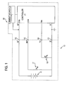
- Battery 10 is connected to a charger control circuit 20.
- Battery 10 comprises a plurality of battery cells 11 connected in series, which dictate the voltage and storage capacity for battery 10.
- Battery 10 preferably includes four battery contacts: first battery contact 12, second battery contact 13, third battery contact 14 and fourth battery contact 15.
- Battery contact 12 is the B+ (positive) terminal for battery 10.
- Battery contact 13 is the B- or negative/common terminal.
- Battery contact 14 is the TC or temperature/communication terminal.
- Battery contact 15 is the IDP or identification terminal.
- Battery contacts 12 and 13 receive the charging current sent from the charger control circuit 20 (preferably from current source 22, as discussed below) for charging the battery 10.
- the battery cells 11 are coupled between the battery contacts 12 and 13.
- a temperature sensing device 16 such as a negative temperature co-efficient (NTC) resistor, or thermistor, R T .
- NTC negative temperature co-efficient
- the temperature sensing device 16 is preferably in close physical proximity to the cells 11 for monitoring of the battery temperature.
- other components such as capacitors, etc., or circuits can be used to provide a signal representative of the battery temperature.
- the charger control circuit 20 preferably comprises a controller 21, which may be a microprocessor.
- Controller 21 may include positive terminal B+ and negative terminal B-, which are coupled to battery 10 via battery contacts 12 and 13, respectively.
- the positive terminal may also act as an input VIN, in order for the controller 21 to detect the battery voltage.
- the controller 21 may include an input TIN, which is coupled to the temperature sensing device 16 via the TC battery contact 14. This allows the controller 21 to monitor the battery temperature.
- Controller 21 may control a current source 22 that provides current to battery 10. This current may be a fast charging current and/or an equalization current.
- Current source 22 may be integrated within controller 21.
- current source 22 is designed to produce different fixed current outputs, rather than constantly variable outputs. Such current source 22 would be easy to design and inexpensive to manufacture.
- Controller 21 may also have an input IDIN, which is coupled to the IDP terminal 15. This input is used in part by the controller 21 to identify the type and capacity of the battery to be charged.
- a battery identification device 17 may be connected to the IDP terminal to provide the identification information to controller 21.
- a battery identification device 17 in this case a resistor R id , is connected between the IDP terminal and the negative terminal B-. The value of resistor R id (and thus the voltage drop across the resistor) is selected to indicate the type and capacity of battery 10. Because of the voltage drop caused by resistor R id , the controller 21 receives via IDIN input an analog signal which can be interpreted by the controller 21 to indicate the type and capacity of battery 10. Controller 21 can then modify any and/or all charging parameters, such as charging voltage, current and time, in order to minimize charging time and/or avoid overcharging.
- the range of voltage drop can be mapped out and programmed into controller 21 so that, upon input of a signal via the IDIN input, the controller 21 can access the programmed values and determine the type and capacity of the battery. Accordingly, the controller 21 may be programmed to recognize that if the ID value ranges between 50 and 106, the battery 10 contains nickel-cadmium (NiCd) cells. Similarly, ID values between 112 and 160 may indicate that the battery 10 contains nickel metal hydride (NiMH) cells.
- NiCd nickel-cadmium
- ID values between 112 and 160 may indicate that the battery 10 contains nickel metal hydride (NiMH) cells.
- ID values between 180 and 230 may indicate that battery 10 contains fixed-voltage cell technologies, such as lead acid or lithium-ion, etc., which needs to be charged under the absolute voltage termination scheme
- the controller may be programmed to recognize that if the ID value is, for example, 56, the battery 10 is a NiCd battery with 1.3 Amps/hour capacity.
- the ID values and their meaning may be stored in a table T. Controller 21 need only then to access table T to determine the type and capacity of the battery. Alternatively, controller 21 may derive the type and capacity of the battery by inputing the ID value into a predetermined equation, preferably of linear form.
- controller 21 can be programmed to recognize batteries incorporating such technologies in order to properly charge them.
- controller 21 uses the signals received via the IDIN input to identify such batteries.
- the ID value ranges may be can be mapped out and programmed into controller 21 (and/or table T) so that, upon input of a signal via the IDIN input, the controller 21 can access the programmed values and determine the required course of action.
- controller 21 may manipulate the ID value in order to determine the required course of action.
- the controller 21 will recognize that it already has the charging methods for these batteries and alter the corresponding charging method according to the type and capacity of the battery. If the ID values are below 50 and/or above 230, the controller 21 then will recognize that it does not have a preprogrammed charging method for this battery. The controller 21 will then stop the charging process or receive the appropriate charging information from the battery.
- the ID value ranges can then be used to identify what kind of information the controller 21 will receive. For example, if the ID values are between 231 and 240, the controller 21 will recognize that the battery will send a list of commands for the controller 21 to execute and that, once the list is transmitted, the battery will not receive any further information from and/or send any further commands to controller 21. Preferably, such list of commands is sent through the TC contact 14. Similarly, if the ID values are below 50, the controller 21 will recognize that the battery is a "smart power-up" battery, as discussed below. Further, if the ID values are above 240, the controller 21 will recognize that the battery is a "full smart" battery, as discussed below.
- the controller 21 is able to distinguish between a battery having a charging method pre-programmed in the controller 21 and a battery that will provide controller 21 with charging instructions.
- the controller 21 is able to make this distinction through the use of a single input line (IDIN).
- the controller 21 preferably detects the battery type and capacity through the use of the same input line.
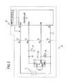
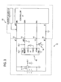
- FIGS. 2 and 3 illustrate two different types of smart batteries.
- battery 10 in addition to the resistor R id , battery 10 has an on-board controller 30 (preferably comprising a microprocessor 31).
- the controller 30 is preferably not normally powered-up and is dormant until the battery 10 is connected to charger 20.
- controller 21 detects that battery 10 is a power-up smart battery (because of the ID value obtained via the IDIN input)
- controller 21 preferably provides enough current and voltage through the IDP terminal to drive controller 30.
- controller 21 relinquishes control of the charging process to controller 30.
- Controllers 21 and 30 preferably communicate via the TC terminal. Controller 30 can then control the charging of battery 10 by providing charger 20 with the steps required to charge the battery.
- controller 30 actively controls the charging process.
- controller 30 issues commands to controller 21 to enable/disable current feed, etc.
- Controller 30 may also request information from controller 21, such as charger status, battery voltage and/or temperature, etc., which controller 30 can then use to carry out the charging process.
- battery 10 has an on-board controller 40 (preferably comprising a microprocessor 41).
- controller 40 is preferably normally powered-up at all times. Such controller 40 can then provide to or receive from the charger and/or device data, such as state-of-charge information. By being normally powered, controller 40 can also log and/or store any data as required.
- controller 21 detects that battery 10 is a power-up smart battery (because of the ID value obtained via the IDIN input)
- controller 21 relinquishes control of the charging process to controller 40.
- controllers 21 and 40 preferably communicate via the TC terminal. Controller 40 can then control the charging of battery 10 by providing charger 20 with the steps required to charge the battery.
- controller 40 actively controls the charging process. In other words, controller 40 issues commands to controller 21 to enable/disable current feed, etc. Controller 40 may also request information from controller 21, such as charger status, battery voltage and/or temperature, etc., which controller 40 can then use to carry out the charging process.
- the preferred current source 22 provides fixed current outputs. Accordingly, battery packs of varying capacities may be charged with this fixed-current output power supply. Thus, it is preferable that the charging method is adaptable to properly charge the different batteries.
- sampling time intervals are selected as a compromises between having a long time interval, accelerating the processing time but risking missing important events between samples, and a short time interval, slowing the processing time to process unimportant events or noise. In other words, if the sample time interval is too long, an event between samples may be missed and the battery may be overcharged. Conversely, if the sample time interval is too long, the charging process may be tenninated prematurely without fully charging the battery.
- sample time intervals be preferably C-rate-specific, otherwise the battery may be overcharged or undercharged.
- the C-rate is equal to the charger current output divided by the battery capacity. Accordingly, the C-rate when a four amp/hour battery is charged by a two amp charger is 0.5C. It has been found that a two amp charger may be used to charge a two amp/hour battery (at a 1C rate), the battery should reach full charge in one hour.
- the termination algorithm used to terminate the charging process may have, for example, a sample time interval of one minute. If a one amp/hour battery is placed in the same two amp charger (at a 2C rate), the battery should reach full charge in 0.5 hours.
- the termination algorithm uses the same sample time interval of one minute, the sampling will be too slow and may cause overcharging of the battery. Similarly, if a four amp/hour battery is placed in the same two amp charger (at a 0.5C rate), the battery should reach full charge in two hours. However, if the termination algorithm uses the same sample time interval of one minute, the sampling will be too fast, causing early termination of the charging process and thus undercharging of the battery.
- the controller 21 may calculate the desired sampling rate by identifying the battery type and capacity, using a prior scheme or the schemes proposed above, calculating the C-rate, and dividing a constant X by the C-rate to determine the length of sampling interval.
- Constant X preferably represents the length of a preferred sampling interval, which may be about 30 or 60 seconds. Persons skilled in the art will recognize that the selected length of the preferred sampling interval involves weighing different considerations, as discussed above.
- the ID value may also be used to provide the proper sampling interval.
- the controller 21 may access a table of stored values representative of different sampling intervals related to different batteries and use the ID value to select the value related to the proper sampling interval from the table.
- the controller 21 may input the ID value into an equation that would provide the proper sampling interval. This equation is preferably linear in nature, i.e., follows the form m(ID value) + b, where m and b are constants selected to provide proper one-to-one correspondence between the range of ID values and the range of sampling intervals.
- controller 21 implement the proper sampling interval automatically.
- the controller 21 can then properly calculate meaningful voltage and/or temperature change rates, and terminate according to methods well known in the art.
- controller 21 may terminate charging after a predetermined number of sampling intervals has elapsed.
- the predetermined number of sampling intervals may range between 30 and 140, where the preferred number of sampling intervals is 120.
- the current source 22 may provide a maintenance and/or equalization current to the battery.
- Such scheme is especially useful for cell chemistries, such as NiCd, that allow the battery to be charged over wide range of charge rates, allowing the battery to be charged as quickly as possible.
- This scheme may also simplify the code for controller 21, if the different voltage curves for the different capacities vary only along the x-axis, i.e., time, rather than on the y-axis, i.e., voltage or temperature.
- This scheme may also be used for cell chemistries, such as NiMH, that cannot accept charging current beyond capacity.
- Another scheme may be used for cell chemistries, such as NiMH, that cannot accept charging current beyond capacity.
- cell chemistries such as NiMH
- the controller 21 repeatedly switches on and off the current source 22, preferably creating a duty cycle where the current is on for a specific period of time and off for a specific period of time.
- the controller 21 need only calculate the length of the "current-on” period, as the length of the "current-off” period will be equal to the length of the duty cycle minus the length of the current-on period.
- the controller 21 may calculate the desired sampling rate by identifying the battery type and capacity, using a prior scheme or the schemes proposed above, calculating the C-rate, and multiplying a constant Y by the C-rate to determine the current-on period length.
- Constant Y preferably represents the length of a duty cycle, which may be about 30 or 60 seconds. Persons skilled in the art will recognize that the selected length of the duty cycle involves weighing different considerations, as known in the art.
- the ID value may also be used to provide the proper current-on period length.
- the controller 21 may access a table of stored values representative of different current sampling intervals related to different batteries and use the ID value to select the value related to the proper current-on period length from the table.
- the controller 21 may input the ID value into an equation that would provide the proper current-on period length. This equation is preferably linear in nature, i.e., follows the form n(ID value) + c, where n and c are constants selected to provide proper one-to-one correspondence between the range of ID values and the range of current-on period lengths.
- the controller 21 implement the proper current-on period length automatically.
- the controller 21 can then properly calculate meaningful voltage and/or temperature change rates, and terminate according to methods well known in the art.
- controller 21 may terminate charging after a predetermined number of sampling intervals has elapsed.
- the predetermined number of sampling intervals may range between 30 and 140, where the preferred number of sampling intervals is 120.
- the current source 22 may provide a maintenance and/or equalization current to the battery.
- sampling interval length coincides with the duty cycle length. It is also preferable that the instant when the battery conditions are sampled be coincident or near coincident with the end of the duty cycle.
- the sampling interval is selected according to the method described above.
Priority Applications (2)
| Application Number | Priority Date | Filing Date | Title |
|---|---|---|---|
| EP08162246A EP1988617A2 (de) | 1998-06-17 | 1999-06-17 | Verfahren und Vorrichtung zum Laden von Batterien |
| EP08162245A EP1988616A2 (de) | 1998-06-17 | 1999-06-17 | Verfahren und Vorrichtung zum Laden von Batterien |
Applications Claiming Priority (2)
| Application Number | Priority Date | Filing Date | Title |
|---|---|---|---|
| US9042798P | 1998-06-17 | 1998-06-17 | |
| US90427P | 1998-06-17 |
Related Child Applications (2)
| Application Number | Title | Priority Date | Filing Date |
|---|---|---|---|
| EP08162246A Division EP1988617A2 (de) | 1998-06-17 | 1999-06-17 | Verfahren und Vorrichtung zum Laden von Batterien |
| EP08162245A Division EP1988616A2 (de) | 1998-06-17 | 1999-06-17 | Verfahren und Vorrichtung zum Laden von Batterien |
Publications (2)
| Publication Number | Publication Date |
|---|---|
| EP0966090A2 true EP0966090A2 (de) | 1999-12-22 |
| EP0966090A3 EP0966090A3 (de) | 2003-04-23 |
Family
ID=22222725
Family Applications (3)
| Application Number | Title | Priority Date | Filing Date |
|---|---|---|---|
| EP08162245A Withdrawn EP1988616A2 (de) | 1998-06-17 | 1999-06-17 | Verfahren und Vorrichtung zum Laden von Batterien |
| EP08162246A Withdrawn EP1988617A2 (de) | 1998-06-17 | 1999-06-17 | Verfahren und Vorrichtung zum Laden von Batterien |
| EP99304742A Withdrawn EP0966090A3 (de) | 1998-06-17 | 1999-06-17 | Verfahren und Vorrichtung zur Ladung von Batterien |
Family Applications Before (2)
| Application Number | Title | Priority Date | Filing Date |
|---|---|---|---|
| EP08162245A Withdrawn EP1988616A2 (de) | 1998-06-17 | 1999-06-17 | Verfahren und Vorrichtung zum Laden von Batterien |
| EP08162246A Withdrawn EP1988617A2 (de) | 1998-06-17 | 1999-06-17 | Verfahren und Vorrichtung zum Laden von Batterien |
Country Status (5)
| Country | Link |
|---|---|
| EP (3) | EP1988616A2 (de) |
| JP (1) | JP2000032674A (de) |
| CN (2) | CN1604423B (de) |
| CA (1) | CA2272943C (de) |
| TW (1) | TW457757B (de) |
Cited By (7)
| Publication number | Priority date | Publication date | Assignee | Title |
|---|---|---|---|---|
| EP1775653A3 (de) * | 2005-10-14 | 2007-05-30 | Research In Motion Limited | Mobiles Kommunikationsgerät mit einem intelligenten Batteriesystem |
| US7667429B2 (en) | 2005-10-14 | 2010-02-23 | Research In Motion Limited | Battery pack authentication for a mobile device |
| US7715884B2 (en) | 2005-10-14 | 2010-05-11 | Research In Motion Limited | Mobile device with a smart battery having a battery information profile corresponding to a communication standard |
| ITPA20090015A1 (it) * | 2009-06-08 | 2010-12-09 | Rosario Marretta | Disposito a logica e componentistica elettronico-digitale per la acquisizione e accumulazione di energia elettrica spillata dal sistema meccanico-elettrico di un veicolo a combustione interna (otto, diesel, brayton-joule, sabathe') alimentato da carb |
| DE102010036397A1 (de) * | 2010-07-14 | 2012-01-19 | Dr. Ing. H.C. F. Porsche Aktiengesellschaft | Automatische Erkennung einer Zellchemie bzw. eines Batterietyps einer Batterie |
| DE102010041510A1 (de) | 2010-09-28 | 2012-03-29 | Robert Bosch Gmbh | Elektrisches Energiespeichersystem und Aufladeverfahren |
| EP2654175B1 (de) * | 2011-01-17 | 2016-10-12 | ZTE Corporation | Batterieschutzvorrichtung und -verfahren für eine gleichstromversorgung |
Families Citing this family (15)
| Publication number | Priority date | Publication date | Assignee | Title |
|---|---|---|---|---|
| US7176654B2 (en) | 2002-11-22 | 2007-02-13 | Milwaukee Electric Tool Corporation | Method and system of charging multi-cell lithium-based batteries |
| KR101094045B1 (ko) | 2005-05-09 | 2011-12-19 | 엘지전자 주식회사 | 배터리 단자 |
| KR20070008048A (ko) * | 2005-07-12 | 2007-01-17 | 엘지전자 주식회사 | 배터리의 충전제어장치 및 방법 |
| US20070069689A1 (en) * | 2005-09-27 | 2007-03-29 | Shum King M | Battery charger |
| JP4241714B2 (ja) | 2005-11-17 | 2009-03-18 | パナソニック電工株式会社 | 電動工具用の電池パック |
| JP2010522533A (ja) * | 2007-03-26 | 2010-07-01 | ザ ジレット カンパニー | 電池検出を備える超高速電池充電器 |
| US20100191490A1 (en) * | 2007-07-09 | 2010-07-29 | Koninklijke Philips Electronics N.V. | Method and device for determining the state of charge of a battery |
| JP4831179B2 (ja) * | 2009-02-17 | 2011-12-07 | パナソニック電工株式会社 | 充電制御装置 |
| JP2011212792A (ja) * | 2010-03-31 | 2011-10-27 | Makita Corp | 電動工具 |
| CN102751541B (zh) * | 2011-04-22 | 2015-02-04 | 比亚迪股份有限公司 | 一种电池管理方法、系统、电池识别方法及电池控制装置 |
| JP6040743B2 (ja) * | 2012-12-07 | 2016-12-07 | 日立工機株式会社 | 充電装置 |
| CN105553060A (zh) * | 2016-01-22 | 2016-05-04 | 中达电通股份有限公司 | 电动车辆的充电系统及充电方法 |
| CN108569144B (zh) * | 2017-03-13 | 2020-06-02 | 宁德时代新能源科技股份有限公司 | 应用于电动客车的电池防失效切断系统 |
| CN111308357B (zh) * | 2020-04-01 | 2022-10-28 | 一汽解放汽车有限公司 | 电池容量估算方法、电池管理系统、车辆及存储介质 |
| CN113190062B (zh) * | 2021-04-27 | 2022-07-26 | 上海烟草集团有限责任公司 | 一种恒温控制方法、恒温控制系统及电加热烟具 |
Citations (3)
| Publication number | Priority date | Publication date | Assignee | Title |
|---|---|---|---|---|
| US5696435A (en) | 1982-06-07 | 1997-12-09 | Norand Corporation | Fast battery charger for a device having a varying electrical load during recharging |
| US5744937A (en) | 1995-10-12 | 1998-04-28 | Samsung Electronics Co., Ltd. | Dual battery charging device for charging nickel metal-hydride and lithium-ion batteries |
| EP0966547B1 (de) | 1997-03-13 | 2001-10-04 | Thyssen Krupp Stahl AG | Verfahren zur herstellung eines bandstahles mit hoher festigkeit und guter umformbarkeit |
Family Cites Families (15)
| Publication number | Priority date | Publication date | Assignee | Title |
|---|---|---|---|---|
| US4388582A (en) | 1978-05-31 | 1983-06-14 | Black & Decker Inc. | Apparatus and method for charging batteries |
| US4392101A (en) | 1978-05-31 | 1983-07-05 | Black & Decker Inc. | Method of charging batteries and apparatus therefor |
| US4845419A (en) * | 1985-11-12 | 1989-07-04 | Norand Corporation | Automatic control means providing a low-power responsive signal, particularly for initiating data preservation operation |
| US5164652A (en) * | 1989-04-21 | 1992-11-17 | Motorola, Inc. | Method and apparatus for determining battery type and modifying operating characteristics |
| US5365160A (en) * | 1991-09-06 | 1994-11-15 | Telxon Corporation | Apparatus and method for charging batteries |
| US5422560A (en) * | 1991-09-30 | 1995-06-06 | Telcom Semiconductor, Inc. | Battery charger with battery detection circuit |
| EP0539640A1 (de) * | 1991-10-30 | 1993-05-05 | Texas Instruments Limited | Batterieverbesserungen |
| US5332957A (en) * | 1992-08-31 | 1994-07-26 | Motorola, Inc. | Battery module and charger |
| US5633573A (en) * | 1994-11-10 | 1997-05-27 | Duracell, Inc. | Battery pack having a processor controlled battery operating system |
| US5572110A (en) * | 1994-12-15 | 1996-11-05 | Intel Corporation | Smart battery charger system |
| WO1996031892A1 (en) * | 1995-04-03 | 1996-10-10 | Motorola Inc. | Thermal sensing device comprising a capacitor with dielectric layer of space charge polarization material |
| US5625291A (en) * | 1995-05-16 | 1997-04-29 | Brink; Gregory D. | System for exchanging information in a battery mailbox |
| AU3803097A (en) * | 1996-07-17 | 1998-02-09 | Duracell Inc. | Battery operating system |
| US5717307A (en) * | 1996-07-24 | 1998-02-10 | Motorola, Inc. | Apparatus and method for identifying the type and brand of a battery for a portable device |
| KR100281536B1 (ko) * | 1997-01-06 | 2001-02-15 | 윤종용 | 밧데리 감지 및 제어기능을 갖는 컴퓨터 |
-
1999
- 1999-05-20 CA CA002272943A patent/CA2272943C/en not_active Expired - Fee Related
- 1999-05-25 TW TW088108507A patent/TW457757B/zh not_active IP Right Cessation
- 1999-06-10 CN CN2004100899926A patent/CN1604423B/zh not_active Expired - Fee Related
- 1999-06-10 CN CNB991083652A patent/CN1180521C/zh not_active Expired - Fee Related
- 1999-06-11 JP JP11165297A patent/JP2000032674A/ja active Pending
- 1999-06-17 EP EP08162245A patent/EP1988616A2/de not_active Withdrawn
- 1999-06-17 EP EP08162246A patent/EP1988617A2/de not_active Withdrawn
- 1999-06-17 EP EP99304742A patent/EP0966090A3/de not_active Withdrawn
Patent Citations (3)
| Publication number | Priority date | Publication date | Assignee | Title |
|---|---|---|---|---|
| US5696435A (en) | 1982-06-07 | 1997-12-09 | Norand Corporation | Fast battery charger for a device having a varying electrical load during recharging |
| US5744937A (en) | 1995-10-12 | 1998-04-28 | Samsung Electronics Co., Ltd. | Dual battery charging device for charging nickel metal-hydride and lithium-ion batteries |
| EP0966547B1 (de) | 1997-03-13 | 2001-10-04 | Thyssen Krupp Stahl AG | Verfahren zur herstellung eines bandstahles mit hoher festigkeit und guter umformbarkeit |
Cited By (18)
| Publication number | Priority date | Publication date | Assignee | Title |
|---|---|---|---|---|
| US8543162B2 (en) | 2005-10-14 | 2013-09-24 | Blackberry Limited | Interface and communication protocol for a mobile device with a smart battery |
| US7697957B2 (en) | 2005-10-14 | 2010-04-13 | Research In Motion Limited | Interface and communication protocol for a mobile device with a smart battery |
| US8280454B2 (en) | 2005-10-14 | 2012-10-02 | Research In Motion Limited | Mobile device with a smart battery having a battery information profile corresponding to a communication standard |
| US8280439B2 (en) | 2005-10-14 | 2012-10-02 | Research In Motion Limited | Interface and communication protocol for a mobile device with a smart battery |
| US8278870B2 (en) | 2005-10-14 | 2012-10-02 | Research In Motion Limited | Battery pack authentication for a mobile communication device |
| US8032187B2 (en) | 2005-10-14 | 2011-10-04 | Research In Motion Limited | Mobile device with a smart battery having a battery information profile corresponding to a communication standard |
| US8670799B2 (en) | 2005-10-14 | 2014-03-11 | Blackberry Limited | Interface and communication protocol for a mobile device with a smart battery |
| US8639219B2 (en) | 2005-10-14 | 2014-01-28 | Blackberry Limited | Battery pack authentication for a mobile communication device |
| US8554284B2 (en) | 2005-10-14 | 2013-10-08 | Blackberry Limited | Mobile device with a smart battery having a battery information profile corresponding to a communication standard |
| US7667429B2 (en) | 2005-10-14 | 2010-02-23 | Research In Motion Limited | Battery pack authentication for a mobile device |
| US7715884B2 (en) | 2005-10-14 | 2010-05-11 | Research In Motion Limited | Mobile device with a smart battery having a battery information profile corresponding to a communication standard |
| US8285327B2 (en) | 2005-10-14 | 2012-10-09 | Research In Motion Limited | Interface and communication protocol for a mobile communication device with a smart battery |
| EP1775653A3 (de) * | 2005-10-14 | 2007-05-30 | Research In Motion Limited | Mobiles Kommunikationsgerät mit einem intelligenten Batteriesystem |
| ITPA20090015A1 (it) * | 2009-06-08 | 2010-12-09 | Rosario Marretta | Disposito a logica e componentistica elettronico-digitale per la acquisizione e accumulazione di energia elettrica spillata dal sistema meccanico-elettrico di un veicolo a combustione interna (otto, diesel, brayton-joule, sabathe') alimentato da carb |
| DE102010036397A1 (de) * | 2010-07-14 | 2012-01-19 | Dr. Ing. H.C. F. Porsche Aktiengesellschaft | Automatische Erkennung einer Zellchemie bzw. eines Batterietyps einer Batterie |
| DE102010041510A1 (de) | 2010-09-28 | 2012-03-29 | Robert Bosch Gmbh | Elektrisches Energiespeichersystem und Aufladeverfahren |
| US9853491B2 (en) | 2011-01-17 | 2017-12-26 | Xi'an Zhongxing New Software Co., Ltd. | Battery protection device and method for DC power supply |
| EP2654175B1 (de) * | 2011-01-17 | 2016-10-12 | ZTE Corporation | Batterieschutzvorrichtung und -verfahren für eine gleichstromversorgung |
Also Published As
| Publication number | Publication date |
|---|---|
| CN1180521C (zh) | 2004-12-15 |
| CN1604423B (zh) | 2010-05-12 |
| EP0966090A3 (de) | 2003-04-23 |
| EP1988617A2 (de) | 2008-11-05 |
| CN1239336A (zh) | 1999-12-22 |
| CA2272943A1 (en) | 1999-12-17 |
| TW457757B (en) | 2001-10-01 |
| JP2000032674A (ja) | 2000-01-28 |
| CA2272943C (en) | 2008-08-12 |
| EP1988616A2 (de) | 2008-11-05 |
| CN1604423A (zh) | 2005-04-06 |
Similar Documents
| Publication | Publication Date | Title |
|---|---|---|
| US6175211B1 (en) | Battery pack with identification device | |
| CA2272943C (en) | Apparatus for charging batteries | |
| JP7198293B2 (ja) | 電池充電器 | |
| US5744937A (en) | Dual battery charging device for charging nickel metal-hydride and lithium-ion batteries | |
| US9118189B2 (en) | Method and system for charging multi-cell lithium-based battery packs | |
| US6218806B1 (en) | Method and apparatus for obtaining product use information | |
| US20010000212A1 (en) | Battery system providing indicia of a charging parameter | |
| CN1989675B (zh) | 用于给电池充电的方法和系统 | |
| EP1717926A2 (de) | Batterieladegerät | |
| GB2396755A (en) | Battery charger for several nominal voltages | |
| US20080174263A1 (en) | Battery charger for different capacity cells | |
| US5617005A (en) | Method and apparatus for charging lead acid batteries | |
| KR101750781B1 (ko) | 전기 자동차용 배터리 충전제어시스템 | |
| US20070035274A1 (en) | Method and apparatus for obtaining product use information | |
| JPH06141482A (ja) | 充電制御回路 |
Legal Events
| Date | Code | Title | Description |
|---|---|---|---|
| PUAI | Public reference made under article 153(3) epc to a published international application that has entered the european phase |
Free format text: ORIGINAL CODE: 0009012 |
|
| AK | Designated contracting states |
Kind code of ref document: A2 Designated state(s): AT BE CH CY DE DK ES FI FR GB GR IE IT LI LU MC NL PT SE |
|
| AX | Request for extension of the european patent |
Free format text: AL;LT;LV;MK;RO;SI |
|
| PUAL | Search report despatched |
Free format text: ORIGINAL CODE: 0009013 |
|
| AK | Designated contracting states |
Designated state(s): AT BE CH CY DE DK ES FI FR GB GR IE IT LI LU MC NL PT SE |
|
| AX | Request for extension of the european patent |
Extension state: AL LT LV MK RO SI |
|
| 17P | Request for examination filed |
Effective date: 20030519 |
|
| AKX | Designation fees paid |
Designated state(s): DE FR GB |
|
| 17Q | First examination report despatched |
Effective date: 20071213 |
|
| TPAC | Observations filed by third parties |
Free format text: ORIGINAL CODE: EPIDOSNTIPA |
|
| STAA | Information on the status of an ep patent application or granted ep patent |
Free format text: STATUS: THE APPLICATION IS DEEMED TO BE WITHDRAWN |
|
| 18D | Application deemed to be withdrawn |
Effective date: 20140103 |