EP0966059A1 - Vier Quadranten-Gruppenantenne - Google Patents
Vier Quadranten-Gruppenantenne Download PDFInfo
- Publication number
- EP0966059A1 EP0966059A1 EP99201594A EP99201594A EP0966059A1 EP 0966059 A1 EP0966059 A1 EP 0966059A1 EP 99201594 A EP99201594 A EP 99201594A EP 99201594 A EP99201594 A EP 99201594A EP 0966059 A1 EP0966059 A1 EP 0966059A1
- Authority
- EP
- European Patent Office
- Prior art keywords
- sum
- radiators
- quadrant
- array antenna
- outer portion
- Prior art date
- Legal status (The legal status is an assumption and is not a legal conclusion. Google has not performed a legal analysis and makes no representation as to the accuracy of the status listed.)
- Granted
Links
- 238000000034 method Methods 0.000 claims abstract description 10
- 238000009826 distribution Methods 0.000 claims description 22
- 238000013459 approach Methods 0.000 description 3
- 238000010586 diagram Methods 0.000 description 3
- 238000003491 array Methods 0.000 description 1
- 238000010276 construction Methods 0.000 description 1
- 238000005457 optimization Methods 0.000 description 1
Images




Classifications
-
- H—ELECTRICITY
- H01—ELECTRIC ELEMENTS
- H01Q—ANTENNAS, i.e. RADIO AERIALS
- H01Q21/00—Antenna arrays or systems
- H01Q21/06—Arrays of individually energised antenna units similarly polarised and spaced apart
- H01Q21/061—Two dimensional planar arrays
- H01Q21/064—Two dimensional planar arrays using horn or slot aerials
-
- H—ELECTRICITY
- H01—ELECTRIC ELEMENTS
- H01Q—ANTENNAS, i.e. RADIO AERIALS
- H01Q25/00—Antennas or antenna systems providing at least two radiating patterns
- H01Q25/02—Antennas or antenna systems providing at least two radiating patterns providing sum and difference patterns
-
- H—ELECTRICITY
- H01—ELECTRIC ELEMENTS
- H01Q—ANTENNAS, i.e. RADIO AERIALS
- H01Q3/00—Arrangements for changing or varying the orientation or the shape of the directional pattern of the waves radiated from an antenna or antenna system
- H01Q3/26—Arrangements for changing or varying the orientation or the shape of the directional pattern of the waves radiated from an antenna or antenna system varying the relative phase or relative amplitude of energisation between two or more active radiating elements; varying the distribution of energy across a radiating aperture
- H01Q3/30—Arrangements for changing or varying the orientation or the shape of the directional pattern of the waves radiated from an antenna or antenna system varying the relative phase or relative amplitude of energisation between two or more active radiating elements; varying the distribution of energy across a radiating aperture varying the relative phase between the radiating elements of an array
- H01Q3/34—Arrangements for changing or varying the orientation or the shape of the directional pattern of the waves radiated from an antenna or antenna system varying the relative phase or relative amplitude of energisation between two or more active radiating elements; varying the distribution of energy across a radiating aperture varying the relative phase between the radiating elements of an array by electrical means
Definitions
- This invention relates to array antennas and, more specifically, to the side lobe patterns generated by those antennas.
- graph 10 shows an example of a sum pattern 12 and difference pattern 14 of a conventional corporate-fed standing wave array antenna.
- the sum pattern 12 has low sum pattern side lobes 16.
- the difference pattern 14 has relatively high side lobes 18.
- the array aperture sum amplitude distribution 20 and difference amplitude distribution 22 are usually optimized for low sum pattern side lobes 16. The optimization creates an abrupt change at the center 24 of the difference amplitude distribution 22. It is this abrupt change, or discontinuity of the amplitude distribution, that produces the very high difference pattern side lobes 18.
- a radar system comprising an array antenna of relatively simple construction that provides low difference side lobes is needed.
- the radar system has a corporate-fed wave guide standing wave array antenna comprising radiators distributed amongst four quadrants A, B, C, and D.
- the quadrants are arranged in a clockwise order of A, B, D, and C.
- Each quadrant is further divided into an inner portion and an outer portion.
- the monopulse sum pattern is determined by adding signals from radiators in both the inner and outer portions of the A quadrant, B quadrant, C quadrant, and D quadrant.
- the elevation difference pattern is determined by subtracting signals received by radiators in the C outer portion and the D outer portion from signals received by radiators in the A outer portion and the B outer portion.
- the azimuth difference pattern is determined by subtracting signals received by radiators in the B outer portion and the D outer portion from signals received by radiators in the A outer portion and the C outer portion.
- the aperture array antenna is a passive phased array antenna.
- the passive phased array antenna has an outer quad array corporate feed that is functionally connected to the radiators in the aperture array antenna outer portions and an inner quad array corporate feed that is functionally connected to the radiators in the aperture array antenna inner portions.
- the aperture array antenna is an active aperture phased array antenna.
- the radar system has an active aperture phased array antenna that has an outer quad array receive corporate feed that is functionally connected to the radiators in the aperture array antenna outer portions and an inner quad array receive corporate feed that is functionally connected to the radiators in the aperture array antenna inner portions.
- the aperture array antenna is an active aperture phased array antenna.
- the radiators are independently controlled by corporate feed networks that transmit a sum signal and receive both sum and difference signals.
- the sum signal is received by an independently controllable sum aperture distribution corporate feed network.
- the difference signals are received by another independently controllable difference aperture distribution corporate feed network.
- the shapes of the inner and outer portions of the aperture array antenna are designed to achieve predetermined difference patterns.
- the shapes of the inner and outer portions of the aperture array antenna are designed to optimize the sum, elevation difference, and azimuth difference patterns.
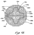
- an array aperture 100a has a surface 102a covered with radiators 104a.
- the surface 102a is divided into an A quadrant 106a, a B quadrant 108a, a C quadrant 110a, and a D quadrant 112a.
- the term "quadrant" is defined as approximately one quarter of the surface and may, or may not, have borders that align with the radii of the aperture.
- the clockwise order of the quadrants is the A quadrant 106a, the B quadrant 108a, the D quadrant 112a, and the C quadrant 110a.
- the A quadrant 106a has an a inner portion 114a and an A outer portion 116a.
- the B quadrant 108a has a b inner portion 118a and a B outer portion 120a.
- the C quadrant 110a has a c inner portion 122a and a C outer portion 124a.
- the D quadrant 112a has a d inner portion 126a and a D outer portion 128a.
- the designation "inner portion” does not imply that the inner portions for other embodiments of the invention are wholly surrounded by the outer portions, as is the case in the instant embodiment. Further, other embodiments of the invention may have discontinuous portions.
- an array aperture 100b comprises inner portions 114b, 118b, 122b, and 126b that extend to the perimeter 101b of the aperture.
- the surface 102b is divided into an A quadrant 106b, a B quadrant 108b, a C quadrant 110b, and a D quadrant 112b.
- the clockwise order of the quadrants is the A quadrant 106b, the B quadrant 108b, The D quadrant 112b, and the C quadrant 110b.
- the A, B, C, D outer portions 116b, 120b, 124b, and 128b of the array aperture 100b are adjacent the a, b, c, d inner portions 114b, 118b, 122b, and 126b. More specifically, the a inner portion 114b straddles a centerline 103 between the A quadrant 106b and the B quadrant 108b. Further, The b inner portion 118b straddles a centerline 105 between the B quadrant 106b and the D quadrant 112b. Additionally, the d inner portion 126b straddles the centerline 103 between the D quadrant 112b and the C quadrant 110b.
- the c inner portion 122b straddles the centerline 105 between the C quadrant 110b and the A quadrant 106b.
- the term "quadrant" should be loosely interpreted to mean that a quadrant is comprised of an outer portion and an inner portion that is approximately one quarter of the array.
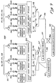
- the radiators 104 are functionally connected to an outer quad array corporate feed 130 and an inner quad array corporate feed 132. More specifically, the radiators 104 in the A, B, C, D outer portions 116, 120, 124, and 128 are functionally connected to the feed 130 and the radiators 104 in the a, b, c, d inner portions 114, 118, 122, and 126 are functionally connected to the feed 132.
- the feed 130 identifies and outputs the signals 134, 136, 138, and 140 coming from A, B, C, D outer portions 116, 120, 124, and 128, respectively.
- the feed 132 identifies and outputs the signals 142, 144, 146, and 148 coming from a, b, c, d inner portions 114, 118, 122, and 126, respectively.
- the outputs from the feeds 130 and 132 are combined to form a sum signal 150, an elevation difference signal 152, and an azimuth difference signal 154.
- the signals 142, 144, 146, and 148 are combined into an [a b+c+d] signal 156 and the signals 134, 136, 138, and 140 are combined into [A+B+C+D] signal 158.
- the [A+B+C+D] signal 158 is then combined with the [ b+c+d] signal 156 to form the sum signal 150.
- the signals 138 and 140 are combined into a (C+D) signal 160 and the signals 134 and 136 are combined into an (A+B) signal 162.
- the (C+D) signal 160 is subtracted from the (A+B) signal 162 to form the elevation difference signal 152.
- the signal 136 is subtracted from the signal 134 to form an (A-B) signal 163, and the signal 140 is subtracted from the signal 138 to form a (C-D) signal 161.
- the (A-B) signal 163 and the (C-D) signal 161 are then combined to form the elevation difference signal [(A+C) - (B+D)] 154.
- an array aperture sum amplitude distribution 166 of the sum signal 150 is the same as the array aperture sum distribution 20 of the prior art (see Figure 2).
- graph 172 shows a sum pattern 174, the prior art difference pattern 14, and a difference pattern 176.
- the sum pattern 174 is the same as the sum pattern 12 of the prior art.
- the result of not using the a, b, c, d signals 142 through 148 from the a, b, c, d inner portions 114, 118, 122, and 126 results in a difference pattern 176 that has much lower difference side lobes 178 compared to the relatively high difference side lobes 18 of the difference pattern 14 of the prior art.
- the size and shape of the difference side lobes may be predetermined by a designer of apertures choosing appropriate shapes of the A, B, C, D outer portions 116, 120, 124, and 128 and the a, b, c, d inner portions 114, 118, 122, and 126 using techniques commonly known in the art. Likewise, the size and shapes of the difference side lobes may also be optimized using techniques commonly known in the art.
- a radar system's active aperture phased array antenna 200 is similar to the passive aperture array antenna 129 (see Figure 5) except for the feeds.
- the transmit sum feed and the receive sum and difference feeds are independently optimized for the best system performance, but the receive difference feed networks are not independent of the receive sum network.
- the antenna 200 has an outer quad array receive feed 202 functionally connected to the radiators 104 of A, B, C, D portions 116, 120, 124, and 128.
- the embodiment shown in Figure 9 also has an inner quad array receive feed 204 functionally connected to the radiators 104 of a, b, c, d portions 114, 118, 122, and 126.
- a radar system's active aperture phased array antenna 210 is similar to the active aperture phased array antenna 200 but for the radiators 212 and the feeds 218 and 220.
- the radiators 212 are independently controlled and each radiator receives a sum signal 214 and a difference signal 216.
- the sum signals 214 are received by an independently controllable sum aperture feed network 218.
- the difference signals 216 are received by an independently controllable difference aperture feed network 220.
- the array aperture does not need to separate into inner portions 114, 118, 122, 126, and the outer portions 116, 120, 124, 128, to achieve predetermined array aperture amplitude distributions to obtain low sum and difference side lobe patterns because the receive difference aperture distributions are independent of the sum aperture distribution.
Landscapes
- Variable-Direction Aerials And Aerial Arrays (AREA)
- Radar Systems Or Details Thereof (AREA)
Applications Claiming Priority (2)
| Application Number | Priority Date | Filing Date | Title |
|---|---|---|---|
| US98409 | 1998-06-16 | ||
| US09/098,409 US6005512A (en) | 1998-06-16 | 1998-06-16 | Array antennas with low sum and difference pattern side lobes and method of producing same |
Publications (2)
| Publication Number | Publication Date |
|---|---|
| EP0966059A1 true EP0966059A1 (de) | 1999-12-22 |
| EP0966059B1 EP0966059B1 (de) | 2002-11-13 |
Family
ID=22269151
Family Applications (1)
| Application Number | Title | Priority Date | Filing Date |
|---|---|---|---|
| EP99201594A Expired - Lifetime EP0966059B1 (de) | 1998-06-16 | 1999-05-20 | Vier Quadranten-Gruppenantenne |
Country Status (3)
| Country | Link |
|---|---|
| US (1) | US6005512A (de) |
| EP (1) | EP0966059B1 (de) |
| DE (1) | DE69903882T2 (de) |
Families Citing this family (5)
| Publication number | Priority date | Publication date | Assignee | Title |
|---|---|---|---|---|
| JP3306657B2 (ja) * | 2000-01-26 | 2002-07-24 | 独立行政法人産業技術総合研究所 | 角度補正方法 |
| US6670931B2 (en) | 2001-11-19 | 2003-12-30 | The Boeing Company | Antenna having cross polarization improvement using rotated antenna elements |
| JP5228979B2 (ja) * | 2009-02-17 | 2013-07-03 | 日本電気株式会社 | アンテナビーム形成方法およびアレイアンテナ |
| US8593334B2 (en) * | 2011-07-29 | 2013-11-26 | The Boeing Company | Split aperture monopulse antenna system |
| CN115425397B (zh) * | 2022-08-31 | 2024-05-10 | 西安电子科技大学 | 一种用于w波段的低副瓣稀布相控阵天线 |
Citations (3)
| Publication number | Priority date | Publication date | Assignee | Title |
|---|---|---|---|---|
| US4121220A (en) * | 1975-01-31 | 1978-10-17 | Electronique Marcel Dassault | Flat radar antenna employing circular array of slotted waveguides |
| US4547779A (en) * | 1983-02-10 | 1985-10-15 | Ball Corporation | Annular slot antenna |
| US4754286A (en) * | 1984-10-18 | 1988-06-28 | Siemens Aktiengesellschaft | Line-fed phase controlled antenna |
Family Cites Families (6)
| Publication number | Priority date | Publication date | Assignee | Title |
|---|---|---|---|---|
| US3860934A (en) * | 1973-08-02 | 1975-01-14 | United Aircraft Corp | Unambiguous phase interferometer antenna |
| US3965475A (en) * | 1975-05-30 | 1976-06-22 | The United States Of America As Represented By The United States Administrator Of The National Aeronautics And Space Administration | Switchable beamwidth monopulse method and system |
| FR2595873B1 (fr) * | 1986-03-14 | 1988-09-16 | Thomson Csf | Reseau reflecteur a controle de phases et antenne comportant un tel reseau |
| US4792805A (en) * | 1987-04-28 | 1988-12-20 | Hughes Aircraft Company | Multifunction active array |
| US4882587A (en) * | 1987-04-29 | 1989-11-21 | Hughes Aircraft Company | Electronically roll stabilized and reconfigurable active array system |
| US5068671A (en) * | 1988-06-24 | 1991-11-26 | The United States Of America As Representated By The Secretary Of The Air Force | Orthogonally polarized quadraphase electromagnetic radiator |
-
1998
- 1998-06-16 US US09/098,409 patent/US6005512A/en not_active Expired - Fee Related
-
1999
- 1999-05-20 DE DE69903882T patent/DE69903882T2/de not_active Expired - Lifetime
- 1999-05-20 EP EP99201594A patent/EP0966059B1/de not_active Expired - Lifetime
Patent Citations (3)
| Publication number | Priority date | Publication date | Assignee | Title |
|---|---|---|---|---|
| US4121220A (en) * | 1975-01-31 | 1978-10-17 | Electronique Marcel Dassault | Flat radar antenna employing circular array of slotted waveguides |
| US4547779A (en) * | 1983-02-10 | 1985-10-15 | Ball Corporation | Annular slot antenna |
| US4754286A (en) * | 1984-10-18 | 1988-06-28 | Siemens Aktiengesellschaft | Line-fed phase controlled antenna |
Also Published As
| Publication number | Publication date |
|---|---|
| DE69903882T2 (de) | 2003-03-27 |
| DE69903882D1 (de) | 2002-12-19 |
| EP0966059B1 (de) | 2002-11-13 |
| US6005512A (en) | 1999-12-21 |
Similar Documents
| Publication | Publication Date | Title |
|---|---|---|
| US6140972A (en) | Multiport antenna | |
| US7212163B2 (en) | Circular polarized array antenna | |
| US5434580A (en) | Multifrequency array with composite radiators | |
| CN113823891B (zh) | 天线模组、毫米波雷达以及车辆 | |
| US5457465A (en) | Conformal switched beam array antenna | |
| US20110063170A1 (en) | Radar apparatus for radiating and receiving electric waves having grating lobes | |
| EP1269570B1 (de) | Reflektorantenne mit gemeinsamer apertur und verbessertem zuführungsentwurf | |
| JPH0669713A (ja) | 整相周波数ステアリング形アンテナアレイ | |
| JP2005525771A (ja) | アルキメデス螺旋を含むフェーズドアレイアンテナ素子アレイ及び関連方法 | |
| US6501434B1 (en) | Multi-band corrugated antenna feed horn with a hexagonal aperture and antenna array using same | |
| US6005512A (en) | Array antennas with low sum and difference pattern side lobes and method of producing same | |
| JPH0411122B2 (de) | ||
| EP1032960B1 (de) | Antennenanordnung für eine einzelne frequenz | |
| CN113206372B (zh) | 阵列天线装置及其制备方法和电子设备 | |
| CN115498416B (zh) | 一种边射波束和锥状波束可重构的微带贴片天线 | |
| CN119231192A (zh) | 基于圆环阵列天线的涡旋电磁波的生成方法 | |
| US6169525B1 (en) | High-performance sectored antenna system using low profile broadband feed devices | |
| EP0237110A1 (de) | Peilantennensystem | |
| US4231043A (en) | Technique for reducing near-in sidelobes of an offset antenna | |
| JP3304019B2 (ja) | アレーアンテナ、それを備えた受信装置およびアレーアンテナにおける指向特性決定方法 | |
| CN111541035B (zh) | 一种gnss智能天线布阵优化方法 | |
| CN115425397B (zh) | 一种用于w波段的低副瓣稀布相控阵天线 | |
| JPH10190539A (ja) | ダイバーシチ受信装置 | |
| US6445356B1 (en) | Primary radiator having reduced side lobe | |
| CN220291083U (zh) | 一体化双脊喇叭天线 |
Legal Events
| Date | Code | Title | Description |
|---|---|---|---|
| PUAI | Public reference made under article 153(3) epc to a published international application that has entered the european phase |
Free format text: ORIGINAL CODE: 0009012 |
|
| AK | Designated contracting states |
Kind code of ref document: A1 Designated state(s): DE FR GB |
|
| AX | Request for extension of the european patent |
Free format text: AL;LT;LV;MK;RO;SI |
|
| 17P | Request for examination filed |
Effective date: 20000502 |
|
| AKX | Designation fees paid |
Free format text: DE FR GB |
|
| 17Q | First examination report despatched |
Effective date: 20010215 |
|
| GRAG | Despatch of communication of intention to grant |
Free format text: ORIGINAL CODE: EPIDOS AGRA |
|
| GRAG | Despatch of communication of intention to grant |
Free format text: ORIGINAL CODE: EPIDOS AGRA |
|
| GRAH | Despatch of communication of intention to grant a patent |
Free format text: ORIGINAL CODE: EPIDOS IGRA |
|
| GRAH | Despatch of communication of intention to grant a patent |
Free format text: ORIGINAL CODE: EPIDOS IGRA |
|
| GRAA | (expected) grant |
Free format text: ORIGINAL CODE: 0009210 |
|
| AK | Designated contracting states |
Kind code of ref document: B1 Designated state(s): DE FR GB |
|
| REG | Reference to a national code |
Ref country code: GB Ref legal event code: FG4D |
|
| REF | Corresponds to: |
Ref document number: 69903882 Country of ref document: DE Date of ref document: 20021219 |
|
| ET | Fr: translation filed | ||
| PLBE | No opposition filed within time limit |
Free format text: ORIGINAL CODE: 0009261 |
|
| STAA | Information on the status of an ep patent application or granted ep patent |
Free format text: STATUS: NO OPPOSITION FILED WITHIN TIME LIMIT |
|
| 26N | No opposition filed |
Effective date: 20030814 |
|
| REG | Reference to a national code |
Ref country code: FR Ref legal event code: PLFP Year of fee payment: 18 |
|
| REG | Reference to a national code |
Ref country code: FR Ref legal event code: PLFP Year of fee payment: 19 |
|
| PGFP | Annual fee paid to national office [announced via postgrant information from national office to epo] |
Ref country code: GB Payment date: 20170530 Year of fee payment: 19 Ref country code: DE Payment date: 20170530 Year of fee payment: 19 Ref country code: FR Payment date: 20170525 Year of fee payment: 19 |
|
| REG | Reference to a national code |
Ref country code: DE Ref legal event code: R119 Ref document number: 69903882 Country of ref document: DE |
|
| GBPC | Gb: european patent ceased through non-payment of renewal fee |
Effective date: 20180520 |
|
| PG25 | Lapsed in a contracting state [announced via postgrant information from national office to epo] |
Ref country code: GB Free format text: LAPSE BECAUSE OF NON-PAYMENT OF DUE FEES Effective date: 20180520 Ref country code: FR Free format text: LAPSE BECAUSE OF NON-PAYMENT OF DUE FEES Effective date: 20180531 Ref country code: DE Free format text: LAPSE BECAUSE OF NON-PAYMENT OF DUE FEES Effective date: 20181201 |