EP0965957A2 - Dispositif visant l'identification des pièces de monnaie et/ou répondeurs - Google Patents
Dispositif visant l'identification des pièces de monnaie et/ou répondeurs Download PDFInfo
- Publication number
- EP0965957A2 EP0965957A2 EP99111014A EP99111014A EP0965957A2 EP 0965957 A2 EP0965957 A2 EP 0965957A2 EP 99111014 A EP99111014 A EP 99111014A EP 99111014 A EP99111014 A EP 99111014A EP 0965957 A2 EP0965957 A2 EP 0965957A2
- Authority
- EP
- European Patent Office
- Prior art keywords
- coins
- transponders
- situated
- sliding channel
- channel
- Prior art date
- Legal status (The legal status is an assumption and is not a legal conclusion. Google has not performed a legal analysis and makes no representation as to the accuracy of the status listed.)
- Ceased
Links
Images


Classifications
-
- G—PHYSICS
- G07—CHECKING-DEVICES
- G07D—HANDLING OF COINS OR VALUABLE PAPERS, e.g. TESTING, SORTING BY DENOMINATIONS, COUNTING, DISPENSING, CHANGING OR DEPOSITING
- G07D5/00—Testing specially adapted to determine the identity or genuineness of coins, e.g. for segregating coins which are unacceptable or alien to a currency
- G07D5/08—Testing the magnetic or electric properties
-
- G—PHYSICS
- G07—CHECKING-DEVICES
- G07D—HANDLING OF COINS OR VALUABLE PAPERS, e.g. TESTING, SORTING BY DENOMINATIONS, COUNTING, DISPENSING, CHANGING OR DEPOSITING
- G07D5/00—Testing specially adapted to determine the identity or genuineness of coins, e.g. for segregating coins which are unacceptable or alien to a currency
Definitions
- the present invention relates to electronic devices for identification and storing of credit values, to be used in stations and/or machines for automatic distribution of goods and/or services, video games, etc., with particular reference to devices for identification of predetermined coins or transponders.
- a device of this type e.g. an electronic slot machine, identifies, according to known techniques, The kind of coin introduced therein by the user; if the coin corresponds to one of the models for which the slot machine is used, it is collected, otherwise it is given back to the user.
- the electronic slot machine When the value of the introduced and collected coins reaches the value of a corresponding good and/or service, the electronic slot machine operates the distributor to deliver the article.
- the electronic slot machines of the stations and/or machines for automatic distribution of goods and/or services can be substituted or integrated by another device which is situated on the machine outer surface for introduction and identification of only electronic means for storing credit values.
- the encoded electronic means for credit values storing are distinguished by an identification code and can be charged up to the credit value desired by the user, upon paying a suitable sum of money.
- a suitable device interacts with the transponder, so as to make a credit transition and operate the distributor to deliver the desired article.
- an additional device for identification of transponders changes the aesthetic look of the outer surface of the stations and/or machines for automatic distribution of goods and/or services, video games stations, etc.
- This invention was evolved with the general object of providing a device suited to introduction and identification of either predetermined coins or the electronic means of credit value storing.
- Another object of the present invention is to propose a device which can be used with the already existing slot machines for identification of coins only by adapting them for the introduction and identification, as well as interaction with transponders.
- a further object of the present invention is to propose a device for identification of coins and/or transponders which does not change in any way the aesthetic look of the distributors of goods and/or services, video games stations, etc.
- Still another object of the present invention is to propose a device which prevents a user, previously provided with a suitably transponder, from useless waste of time for looking for big number of coins.
- Yet further object of the present invention is to propose a device for identification and subsequent encoded storing of credit, which is easy to use for anyone and rapid, reducing the time necessary for obtaining required goods and/or services.
- Still a further object of the present invention is to propose a device which not only identifies and interacts with transponders, but also charges them in a rapid and simple way.
- the proposed device is obtained by a simple, extremely reliable technical solution, which is also functional and cheap.
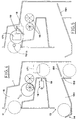
- reference numeral 1 generally designates a box-like case
- numeral 11 indicates a first rectangular slot for introduction of the predetermined coins or circular transponders 10
- numeral 13 indicates a second slot, featuring a stop 14 for a possible rejection of the coin or returning of the transponder.
- the first rectangular slot 11 situated in the upper part of the case 1, on its front surface, accessible from outside, forms a mouth of a sliding channel 15.
- the shape of the channel is such that different types of coins or transponders can be freely received therein.
- the sliding channel 15 extends inside the case 1, from its top downwards, so as to guide the coin or transponder along a well defined path on different levels.
- Detecting and identification means formed by e.g. as in Figure 1, a couple of coils 16, are situated in the sliding channel 15 on its lateral walls and on a first level below the slot 11.
- the detecting and identification means can be also formed by a single coil of any shape, with or without inner core, and adapted to work within any frequency range.
- the coils 16 for identifying predetermined coins and transponders are connected to a control unit 17.
- the coils 16 act as a primary winding and a secondary winding of a transformer and detect possible changes of the medium situated therebetween.
- the coils detect and identify the characteristic features of any type of coin, such as material, mass, geometry, etc.), and if a transponder is introduced into the slot, the coils identify its code.
- Each type of coins and each transponder code is associated with a signal or impulse which will be sent to the control unit 17.
- the control unit 17 is interfaced, by known interface means, with a first actuator 18 situated on the final level of the sliding channel 15, and with a second actuator 181, situated on a lower level, near the mouth of a connecting channel 153.
- the first actuator 18 controls a positioning member 19 situated in the falling area of the sliding channel 15, so as to stop the transponder descent blocking it near an electronic data reading/writing sensor 171.
- the electronic data reading sensor 171 suitably interfaced with the control unit 17 by known connecting means, reads the amount of credit still stored in the transponder.
- the second actuator 181 controls a baffle 191, so as to make it assume two different positions.
- the baffle 191 When in its first position, e.g. indicated with H in Figure 3, the baffle 191 joins the terminal part of the sliding channel 15 to the mouth of the connecting channel 153; when in its second position, indicated with K in Figure 3, the baffle 191 joins the sliding channel 15 to a discharge channel 151, at the end of which there is the second slot 13.
- the joining of the sliding channel 15 to the connecting channel 153 allows to collect coins which have been identified as valid, while joining of the sliding channel 15 to the discharge channel 151 allows to reject the unidentified coins or transponders.
- the joining of the sliding channel 15 and the connecting channel 153 can also allow to collect the transponders out of credit, according to the administrator of the stations and/or automatic machines for distribution of goods and services.
- the baffle 191 can assume either the first position H or the second position K.
- the coin is introduced in the first slot 11 and let fall in the sliding channel 15.
- the coin follows the path defined by the sliding channel 15 and passes between the coils 16 which detect possible changes of the medium situated therebetween.
- the coils send to the control unit 17 a signal corresponding to the detected type of coin.
- control unit 17 If the control unit 17 identifies the type of signal as known and corresponding to a predetermined type of coin, it enables the second actuator 181 to operate the baffle 191 to assume the position in which it joins the sliding channel 15 to connecting channel 153.
- the coin can arrive to the credit storing device and increase the collected credit to reach the value of the desired good and/or service.
- control unit 17 if it does not identify the received signal as known, it enables the second actuator 181 to operate the baffle 191 to assume the position in which it joins the sliding channel 15 to the discharge channel 151, so as to reject the coin which appears on the stop 14 of the second slot 13.
- the transponder of circular form is introduced in the first slot 11 and let fall in the sliding channel 15.
- the transponder follows the path defined by the sliding channel 15 and passes between the coils 16 which detect its identifying code.
- the coils 16 send a signal to the control unit 17 that a transponder with credit stored therein has been introduced.
- the control unit 17 enables the first actuator 18 to operate the positioning member 19, so as to stop the transponder descent near the electronic data reading sensor 171.
- the electronic data reading sensor 171 detects if the credit of the transponder is enough to deliver the desired good and/or service.
- the electronic data reading/writing sensor 171 detracts the sum relative to the required good and/or service from the stored credit value.
- the electronic data reading sensor 171 sends a signal to the first actuator 18 to make the positioning member 19 return, so that the transponder can continue its run.
- the electronic data reading sensor 171 sends a signal to the control unit 17 to operate, by the second actuator 181, the baffle 191, so as to make it assume the position in which it joins the sliding channel 15 and the discharge channel 151.
- the electronic data reading sensor 171 can detect that the transponder is out of credit or that the stored credit value is lower than the requested value.
- the electronic data reading sensor 171 sends a signal to the control unit 17 to operate the second actuator 181, so as to join the sliding channel 15 and the discharge channel 151, in the above described way, so as to return the transponder to the user and possibly communicate him/her, by a suitable display, that the credit stored therein is not big enough or off.
- control unit 17 If requested by the administrator of stations and/or automatic machines for distribution of goods and/or services, it is also possible to program the control unit 17 so that the baffle 191 joins the sliding channel 15 to the connecting channel 153 so as to collect the transponders out of credit.
- the administrator will store new credit values in the transponder, whereas if the transponder is returned to the user, the user himself will store the new credit value therein.
- the proposed device in addition to the coils 16 or instead of them, is equipped with a sensor for identifying transponders with credit values stored therein, interfaced with the control unit 17 by known means.
- the additional (or substitute) sensor can be situated in place of the coils 16 or, as indicated with 161a in Figures 5, 7, immediately after the mouth of the sliding channel 15.
- the electronic data reading/writing sensor 171 and the first actuator 18 with the positioning member 19 are situated immediately after the mouth of the sliding channel 15 and downstream of the sensor 161.
- the device features either the coils 16 or the sensor 161 for identification of transponders and it does not feature the first actuator 18 and the positioning member 19.
- the electronic data reading/writing sensor 171 reads the transponder rapidly, advantageously accelerating the reading operation of the remaining credit and consequently, allowing to optimize the credit accumulation and distribution of the good and/or service.
- the electronic data reading/writing sensor 171 can he situated either at the end of the sliding channel 15 or downstream of the sensor 161a placed immediately after the mouth of the sliding channel 15.
- the location of the electronic data reading/writing sensor 171 can coincide with the location of the coils 16, and the electronic data reading/writing sensor 171 can read the transponder rapidly (without the positioning member 19) or the transponder, stopped by the positioning member 19, can be read in the previously described ways.
- Figure 8 shows a further and particularly interesting embodiment of the proposed device.
- the reference numeral 1 indicates the case of a normal and common slot machine identifying only coins and including the sliding channel 15, the coils 16, the control unit 17, the discharge channel 151, the connecting channel 153 and the baffle 191.
- This slot machine is adapted to identification of transponders by adding an outer unit 3, including an inlet channel 31 which joins with the mouth of the sliding channel 15 in the area of the slot 11.
- a sensor 161b Inside the channel 15 there are situated a sensor 161b, an electronic data reading/writing sensor 171a, and actuator 180 and a positioning member 190.
- the sensor 161b suitably interfaced with the control unit 17 by known means, send a signal to the control unit that a transponder 10 has been introduced and reads its identification code.
- the control unit 17 enables the actuator 180 to operate the positioning member 190 in such a way, as to intercept the transponder and place it in the area of the electronic data reading/writing sensor 171a.
- the electronic data reading/writing sensor 171a interfaced with the control unit 17 by known means, detects possible credit still stored in the transponder 10 and detracts therefrom the sum corresponding to the value of the requested good or service.
- the electronic data reading/writing sensor 171a After having detracted this sum, the electronic data reading/writing sensor 171a send a signal to the control unit 17 to enable the actuator 180 to withdraw the positioning member 190.
- the transponder leaves the inlet channel 31, slides in the sliding channel 15, passes through the connecting channel 153 and is ejected by the slot 13.
- baffle 191 it is possible to position the baffle 191, so as to join the sliding channel 15 with the connecting channel 153 for collecting transponders out of credit.
- the sensor 161b detects that no transponder has been introduced and send a signal to the control unit not to operate the positioning member 190.
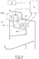
- the proposed device for identification of predetermined coins and/or transponders can be also equipped, as shown in Figure 9, with a credit storing and updating electronic element A, so as to allow the user to personally store now credit values in the transponder out of credit.
- the credit storing and updating electronic element A is interfaced, by known means, with the electronic data reading sensor 171 and the coils 16.
- the transponder If the transponder is out of credit, it is enough to introduce such a number of coins, as to reach the desired value of re-charge; the coils 16 detect the values of single coins and signal it to the electronic element A which stores the credit.
- the user After having reached the desired value, the user introduces the transponder which is stopped by the positioning member in the area of the electronic data reading/writing sensor and the electronic element A updates the transponder credit by the electronic data reading/writing sensor 171.
- the transponder credit can be also read rapidly and in this case there is no positioning member.
- a banknote reader B can be connected to the credit storing and updating electronic element A for accumulating credit necessary to store new credit value in the transponder.
- One of the advantages of the present invention is that it proposes a device, obtained by all described embodiments, which is able to receive and identify predetermined coins as well as credit storing encoded electronic means, like e.g. circular transponders.
- the proposed device can be easily integrated with already used slot machines, adapting these machines to identification of transponders without changing the look of the outer surface of the distributing machines.
- Another advantage of the present invention is that it proposes a device, which is easy to use for anyone and rapid, reducing the time necessary for obtaining required goods and/or services.
Applications Claiming Priority (2)
| Application Number | Priority Date | Filing Date | Title |
|---|---|---|---|
| IT1998BO000382A IT1306301B1 (it) | 1998-06-19 | 1998-06-19 | Dispositivo per il riconoscimento di prefissate monete e/o transponder |
| ITBO980382 | 1998-06-19 |
Publications (2)
| Publication Number | Publication Date |
|---|---|
| EP0965957A2 true EP0965957A2 (fr) | 1999-12-22 |
| EP0965957A3 EP0965957A3 (fr) | 2001-04-11 |
Family
ID=11343254
Family Applications (1)
| Application Number | Title | Priority Date | Filing Date |
|---|---|---|---|
| EP99111014A Ceased EP0965957A3 (fr) | 1998-06-19 | 1999-06-10 | Dispositif visant l'identification des pièces de monnaie et/ou répondeurs |
Country Status (3)
| Country | Link |
|---|---|
| US (1) | US6260686B1 (fr) |
| EP (1) | EP0965957A3 (fr) |
| IT (1) | IT1306301B1 (fr) |
Cited By (8)
| Publication number | Priority date | Publication date | Assignee | Title |
|---|---|---|---|---|
| EP1191489A2 (fr) * | 2000-09-22 | 2002-03-27 | O.T.R. S.r.l. | Dispositif pour l'identification de pièces de monnaie, transpondeurs et/ou moyens de stockage de crédit électronique |
| EP1577853A2 (fr) * | 2004-03-19 | 2005-09-21 | Aruze Corp. | Système de jeu |
| EP1577852A2 (fr) * | 2004-03-19 | 2005-09-21 | Aruze Corp. | Système de jeu |
| EP1585074A2 (fr) * | 2004-04-05 | 2005-10-12 | Aruze Corp. | Machine à sous |
| EP1901240A2 (fr) | 2006-09-13 | 2008-03-19 | Asahi Seiko Co. Ltd. | Dispositif de traitement de support de valeur |
| EP2048630A1 (fr) | 2007-09-12 | 2009-04-15 | Asahi Seiko Co., Ltd. | Dispositif de traitement de support de valeur |
| EP2091027A1 (fr) | 2008-02-14 | 2009-08-19 | Asahi Seiko Co. Ltd. | Appareil de traitement de support de valeur |
| KR101028446B1 (ko) | 2009-07-31 | 2011-04-14 | 아사히 세이코 가부시키가이샤 | 가치 매체 처리 장치 |
Families Citing this family (3)
| Publication number | Priority date | Publication date | Assignee | Title |
|---|---|---|---|---|
| JP2002024775A (ja) * | 2000-07-06 | 2002-01-25 | Nippon Conlux Co Ltd | コイン型icカード用リーダライタ |
| US20070007104A1 (en) * | 2005-06-22 | 2007-01-11 | Piccirillo James S | Electronic coin recognition system |
| US20070068766A1 (en) * | 2005-07-07 | 2007-03-29 | Giridhar Sithamraju | Electronic Coin Wallet |
Citations (3)
| Publication number | Priority date | Publication date | Assignee | Title |
|---|---|---|---|---|
| DE4400744A1 (de) * | 1993-02-20 | 1994-08-25 | Farmont Technik | Ein- und Ausgabevorrichtung für runde, ein Identifikations- und/oder Kommunikationselement aufweisende Parkkarten zur gebührenpflichtigen Betätigung einer Parkschranke |
| US5366058A (en) * | 1991-12-17 | 1994-11-22 | Kabushiki Kaisha Universal | Coin selector and selection method for coin-operated machines for detecting fraud in coin insertion |
| DE19512878A1 (de) * | 1995-04-06 | 1995-11-09 | Meonic Entwicklung Und Geraete | Spielautomat, insbesondere Geldspielautomat |
Family Cites Families (9)
| Publication number | Priority date | Publication date | Assignee | Title |
|---|---|---|---|---|
| CH565420A5 (fr) * | 1973-09-17 | 1975-08-15 | Schulte Schlagbaum Ag | |
| CH594938A5 (fr) * | 1975-10-30 | 1978-01-31 | Landis & Gyr Gmbh | |
| US4185730A (en) * | 1978-04-06 | 1980-01-29 | Cubic Western Data | Magnetically encoded token and handling apparatus |
| EP0147099B1 (fr) * | 1983-12-06 | 1992-06-17 | Mars Incorporated | Jetons et dispositifs pour leur manipulation |
| GB2186411B (en) * | 1986-02-07 | 1990-01-10 | Mars Inc | Apparatus for handling coins and tokens and a combination of a token with such apparatus |
| GB8608264D0 (en) * | 1986-04-04 | 1986-05-08 | Shop Along Bingo Midlands Ltd | Games apparatus |
| GB8628299D0 (en) * | 1986-11-26 | 1986-12-31 | Coin Controls | Token verification system |
| GB2206720A (en) * | 1987-07-10 | 1989-01-11 | Conimaster Mfg Ltd | A coin and token freed apparatus |
| EP0650148B2 (fr) * | 1993-10-18 | 2005-10-12 | Gemplus | Machine de jeux à monnayeur électronique |
-
1998
- 1998-06-19 IT IT1998BO000382A patent/IT1306301B1/it active
-
1999
- 1999-06-10 EP EP99111014A patent/EP0965957A3/fr not_active Ceased
- 1999-06-14 US US09/332,495 patent/US6260686B1/en not_active Expired - Lifetime
Patent Citations (3)
| Publication number | Priority date | Publication date | Assignee | Title |
|---|---|---|---|---|
| US5366058A (en) * | 1991-12-17 | 1994-11-22 | Kabushiki Kaisha Universal | Coin selector and selection method for coin-operated machines for detecting fraud in coin insertion |
| DE4400744A1 (de) * | 1993-02-20 | 1994-08-25 | Farmont Technik | Ein- und Ausgabevorrichtung für runde, ein Identifikations- und/oder Kommunikationselement aufweisende Parkkarten zur gebührenpflichtigen Betätigung einer Parkschranke |
| DE19512878A1 (de) * | 1995-04-06 | 1995-11-09 | Meonic Entwicklung Und Geraete | Spielautomat, insbesondere Geldspielautomat |
Cited By (18)
| Publication number | Priority date | Publication date | Assignee | Title |
|---|---|---|---|---|
| EP1191489A3 (fr) * | 2000-09-22 | 2003-05-14 | O.T.R. S.r.l. | Dispositif pour l'identification de pièces de monnaie, transpondeurs et/ou moyens de stockage de crédit électronique |
| EP1191489A2 (fr) * | 2000-09-22 | 2002-03-27 | O.T.R. S.r.l. | Dispositif pour l'identification de pièces de monnaie, transpondeurs et/ou moyens de stockage de crédit électronique |
| CN100365667C (zh) * | 2004-03-19 | 2008-01-30 | 阿鲁策株式会社 | 币接受装置 |
| EP1577853A2 (fr) * | 2004-03-19 | 2005-09-21 | Aruze Corp. | Système de jeu |
| EP1577852A2 (fr) * | 2004-03-19 | 2005-09-21 | Aruze Corp. | Système de jeu |
| EP1577853A3 (fr) * | 2004-03-19 | 2005-11-16 | Aruze Corp. | Système de jeu |
| EP1577852A3 (fr) * | 2004-03-19 | 2005-11-16 | Aruze Corp. | Système de jeu |
| CN100435895C (zh) * | 2004-03-19 | 2008-11-26 | 阿鲁策株式会社 | 币接受装置 |
| EP1585074A2 (fr) * | 2004-04-05 | 2005-10-12 | Aruze Corp. | Machine à sous |
| CN100346362C (zh) * | 2004-04-05 | 2007-10-31 | 阿鲁策株式会社 | 游戏介质接受装置 |
| EP1585074A3 (fr) * | 2004-04-05 | 2006-04-12 | Aruze Corp. | Machine à sous |
| EP1901240A2 (fr) | 2006-09-13 | 2008-03-19 | Asahi Seiko Co. Ltd. | Dispositif de traitement de support de valeur |
| EP1901240A3 (fr) * | 2006-09-13 | 2008-05-14 | Asahi Seiko Co. Ltd. | Dispositif de traitement de support de valeur |
| KR100897571B1 (ko) | 2006-09-13 | 2009-05-15 | 아사히 세이코 가부시키가이샤 | 가치매체 처리장치 |
| US7677381B2 (en) | 2006-09-13 | 2010-03-16 | Asahi Sieko Co., Ltd. | Value medium processing device |
| EP2048630A1 (fr) | 2007-09-12 | 2009-04-15 | Asahi Seiko Co., Ltd. | Dispositif de traitement de support de valeur |
| EP2091027A1 (fr) | 2008-02-14 | 2009-08-19 | Asahi Seiko Co. Ltd. | Appareil de traitement de support de valeur |
| KR101028446B1 (ko) | 2009-07-31 | 2011-04-14 | 아사히 세이코 가부시키가이샤 | 가치 매체 처리 장치 |
Also Published As
| Publication number | Publication date |
|---|---|
| EP0965957A3 (fr) | 2001-04-11 |
| IT1306301B1 (it) | 2001-06-04 |
| US6260686B1 (en) | 2001-07-17 |
| ITBO980382A1 (it) | 1999-12-19 |
Similar Documents
| Publication | Publication Date | Title |
|---|---|---|
| EP2062230B1 (fr) | Appareil de distribution de pièces de monnaie et appareil de dépôt et de distribution de pièces de monnaie | |
| KR950000946B1 (ko) | 자동판매기의 제어장치 | |
| US6260686B1 (en) | Device for identification of coins and/or transponders | |
| US3978962A (en) | Solid state, coin activated mechanism | |
| JP2008506172A (ja) | 貨幣品払出装置 | |
| EP3827908B1 (fr) | Kit, conteneur et procede de fourniture et de collecte de receptacles reutilisables | |
| US8967362B2 (en) | Apparatus, method, software and graphical interface for flexible dispensing of coins in a coin handling apparatus | |
| EP1607914A1 (fr) | Distributeur de pièces de monnaie configurable | |
| EP1191489B1 (fr) | Dispositif pour l'identification de pièces de monnaie, transpondeurs et moyens de stockage de crédit électronique | |
| US5950795A (en) | Exact change coin collection device | |
| CA2388693C (fr) | Trieuse de monnaie avec leviers de triages | |
| JP2010284403A (ja) | ゲーム機 | |
| EP1555636B1 (fr) | Sélecteur et distributeur de pièces de monnaie | |
| JPH0321285A (ja) | パチンコ玉貸装置 | |
| JP2000093636A (ja) | 遊技媒体貸出機 | |
| CN212032263U (zh) | 一种硬币识别器 | |
| US5377809A (en) | Coin control systems for automatic machines | |
| EP1031950A1 (fr) | Dispositif de manipulation d'argent | |
| AU653162B2 (en) | Improvements to coin control systems for automatic machines | |
| JP2588657Y2 (ja) | 硬貨選別装置 | |
| JPH0246882A (ja) | パチンコ装置 | |
| JP5124803B2 (ja) | メダル預かり払出装置 | |
| JP5286486B2 (ja) | メダル預かり払出装置 | |
| JP2714667B2 (ja) | 自動販売機の釣銭装置 | |
| EP0986030A1 (fr) | Sélecteur électronique de pièces de monnaie |
Legal Events
| Date | Code | Title | Description |
|---|---|---|---|
| PUAI | Public reference made under article 153(3) epc to a published international application that has entered the european phase |
Free format text: ORIGINAL CODE: 0009012 |
|
| AK | Designated contracting states |
Kind code of ref document: A2 Designated state(s): AT BE CH DE ES FR GB IT LI |
|
| AX | Request for extension of the european patent |
Free format text: AL;LT;LV;MK;RO;SI |
|
| PUAL | Search report despatched |
Free format text: ORIGINAL CODE: 0009013 |
|
| RIC1 | Information provided on ipc code assigned before grant |
Free format text: 7G 07D 5/08 A, 7G 07D 3/00 B |
|
| AK | Designated contracting states |
Kind code of ref document: A3 Designated state(s): AT BE CH CY DE DK ES FI FR GB GR IE IT LI LU MC NL PT SE |
|
| AX | Request for extension of the european patent |
Free format text: AL;LT;LV;MK;RO;SI |
|
| 17P | Request for examination filed |
Effective date: 20010508 |
|
| AKX | Designation fees paid |
Free format text: AT BE CH DE ES FR GB IT LI |
|
| 17Q | First examination report despatched |
Effective date: 20020408 |
|
| STAA | Information on the status of an ep patent application or granted ep patent |
Free format text: STATUS: THE APPLICATION HAS BEEN REFUSED |
|
| 18R | Application refused |
Effective date: 20050313 |