EP0965953A1 - Sheet dispensing mechanism - Google Patents
Sheet dispensing mechanism Download PDFInfo
- Publication number
- EP0965953A1 EP0965953A1 EP99304595A EP99304595A EP0965953A1 EP 0965953 A1 EP0965953 A1 EP 0965953A1 EP 99304595 A EP99304595 A EP 99304595A EP 99304595 A EP99304595 A EP 99304595A EP 0965953 A1 EP0965953 A1 EP 0965953A1
- Authority
- EP
- European Patent Office
- Prior art keywords
- unit
- sheet
- transport
- sheets
- dispensing mechanism
- Prior art date
- Legal status (The legal status is an assumption and is not a legal conclusion. Google has not performed a legal analysis and makes no representation as to the accuracy of the status listed.)
- Granted
Links
Images


Classifications
-
- B—PERFORMING OPERATIONS; TRANSPORTING
- B65—CONVEYING; PACKING; STORING; HANDLING THIN OR FILAMENTARY MATERIAL
- B65H—HANDLING THIN OR FILAMENTARY MATERIAL, e.g. SHEETS, WEBS, CABLES
- B65H31/00—Pile receivers
- B65H31/30—Arrangements for removing completed piles
- B65H31/3027—Arrangements for removing completed piles by the nip between moving belts or rollers
-
- B—PERFORMING OPERATIONS; TRANSPORTING
- B65—CONVEYING; PACKING; STORING; HANDLING THIN OR FILAMENTARY MATERIAL
- B65H—HANDLING THIN OR FILAMENTARY MATERIAL, e.g. SHEETS, WEBS, CABLES
- B65H29/00—Delivering or advancing articles from machines; Advancing articles to or into piles
- B65H29/58—Article switches or diverters
-
- B—PERFORMING OPERATIONS; TRANSPORTING
- B65—CONVEYING; PACKING; STORING; HANDLING THIN OR FILAMENTARY MATERIAL
- B65H—HANDLING THIN OR FILAMENTARY MATERIAL, e.g. SHEETS, WEBS, CABLES
- B65H31/00—Pile receivers
- B65H31/02—Pile receivers with stationary end support against which pile accumulates
-
- G—PHYSICS
- G07—CHECKING-DEVICES
- G07D—HANDLING OF COINS OR VALUABLE PAPERS, e.g. TESTING, SORTING BY DENOMINATIONS, COUNTING, DISPENSING, CHANGING OR DEPOSITING
- G07D11/00—Devices accepting coins; Devices accepting, dispensing, sorting or counting valuable papers
- G07D11/40—Device architecture, e.g. modular construction
-
- B—PERFORMING OPERATIONS; TRANSPORTING
- B65—CONVEYING; PACKING; STORING; HANDLING THIN OR FILAMENTARY MATERIAL
- B65H—HANDLING THIN OR FILAMENTARY MATERIAL, e.g. SHEETS, WEBS, CABLES
- B65H2301/00—Handling processes for sheets or webs
- B65H2301/40—Type of handling process
- B65H2301/42—Piling, depiling, handling piles
- B65H2301/421—Forming a pile
- B65H2301/4212—Forming a pile of articles substantially horizontal
-
- B—PERFORMING OPERATIONS; TRANSPORTING
- B65—CONVEYING; PACKING; STORING; HANDLING THIN OR FILAMENTARY MATERIAL
- B65H—HANDLING THIN OR FILAMENTARY MATERIAL, e.g. SHEETS, WEBS, CABLES
- B65H2408/00—Specific machines
- B65H2408/10—Specific machines for handling sheet(s)
- B65H2408/13—Wall or kiosk dispenser, i.e. for positively handling or holding material until withdrawal by user
Definitions
- the present invention relates to a sheet dispensing mechanism.
- the invention has application, for example, to a cash dispensing mechanism of an automated teller machine (ATM).
- An ATM has a user console to allow a customer to operate the machine.
- the cash dispensing mechanism typically includes at least one bill picking mechanism for extracting currency notes or bills one by one from an associated currency cassette, and a presenting mechanism for presenting the bills to an exit slot in the ATM.
- a cash dispensing mechanism of an ATM may be of the rear loading type in which currency cassettes are removed from, and replaced in, the dispensing mechanism from the rear of the ATM, that is on the side opposite the user console, or it may be of the front loading type in which currency cassettes are removed from, and replaced in, the dispensing mechanism from the front of the ATM.
- a through-the-wall ATM in which the user console is mounted in a wall of a bank or other building, includes a cash dispensing mechanism of the rear loading type, while an in-lobby ATM located inside a bank or other building may include a cash dispensing mechanism of either the rear loading or front loading type.
- the present invention has particular application to a dispensing mechanism of an ATM which is of the type that delivers bills one by one in a non-bundled manner (known as a spray dispenser).
- a cash dispensing mechanism which can be modified so as to have either a front loading or a rear loading configuration.
- This known mechanism comprises upper and lower units, the upper unit housing stacking means and transport means for feeding a stack of currency bills to an exit port and for feeding rejected bills to a rejected bill container positioned at the rear of the mechanism, and the lower unit housing currency bill dispensing compartments and transport means for feeding bills to the upper unit.
- the whole of the lower unit is rotatable through 180° with respect to the upper unit during installation, whereby the installed cash dispenser unit can be either front loading or rear loading.
- This arrangement has the potential advantage of increasing the manufacturer's productivity, since it is not necessary to manufacture two different types of cash dispensing mechanisms for front loading and rear loading operations.
- this known cash dispensing mechanism has the disadvantage that complexities are introduced due to the fact that transfer of bills from the lower unit to the upper unit takes place at one or other of two separate transfer stations, depending on whether the mechanism has a front loading or a rear loading configuration.
- adjustable divert means are required, such divert means being liable to give rise to the jamming of the bills.
- a sheet dispensing mechanism including a housing having a sheet dispensing port via which sheets are dispensed to a user of the mechanism, a first unit mounted inside the housing including sheet storage means, picking means for picking sheets one by one from the sheet storage means, and first transport means for transporting sheets from said picking means, and a second unit which is mounted on the first unit within the housing in one of two possible positions depending on whether the dispensing mechanism has a front loading or a rear loading configuration, the second unit being arranged to receive sheets transported upwardly from the first unit, and including second transport means for transporting sheets received from the first unit to the sheet dispensing port.
- the first unit also includes sheet checking means through which sheets transported from the picking means by the first transport means are passed, divert means for directing sheets rejected by sheet checking means into reject means, and third transport means for transporting sheets accepted by the sheet checking means upwardly from the first unit to the second unit at a single transfer station, regardless of whether said dispensing mechanism has a front or rear loading configuration.
- the second transport means is arranged to transport sheets individually from the first unit to the sheet dispensing port.
- an ATM 10 comprises a display 12 for displaying user information, a key pad 14 for inputting data, a card reader 16 for receiving a user identity card via a card slot 18, a cash dispensing mechanism 20 for dispensing currency bills stored in the mechanism 20 to a user during a transaction, via a slot 22, a receipt printer 24 for printing a receipt acknowledging a transaction made by a user and for issuing the receipt to the user via a slot 26, and data processing means 28 to which the display 12, the key pad 14, the card reader 16, the cash dispensing mechanism 20 and the receipt printer 24 are connected.
- a user inserts his identification card in the card slot 18 of the ATM 10.
- Data contained in a magnetic strip on the card is read by the card reader 16 and transmitted by the data processing means 28 to a host computer 30.
- the user identifies himself by entering his personal identity number via the key pad 14. If the host computer 30 authorizes the card then the user can proceed with his withdrawal by first entering details of the transaction, e.g. the amount of the withdrawal by means of the key pad 14.
- This cash dispensing mechanism 20 comprises a safe 40a inside which are housed a lower unit 42 and an upper unit 44.
- the safe 40a is mounted in a housing 45 (see Fig. 1) of the ATM 10.
- the lower unit 42 has lower and upper sections 46,48. Inside the lower section 46 of the lower unit 42 are mounted currency cassettes 50 which are associated with a conventional pick mechanism 52.
- the upper unit 44 is mounted on the lower unit 42 with a selected orientation relative to the lower unit 42 determined by the fact that the cash dispensing mechanism 20 has a rear loading configuration.
- the data processing means 28 causes the pick mechanism 52 to pick bills in a known manner from at least one cassette 50. Each bill is picked singly and the bills are individually passed along a feed path (indicated by arrow 54) by conventional bill transport means 55 included in the lower section 46.
- the feed path takes the bill from the lower section 46 to a conventional bill validator 58 in the upper section 48. If the bill validator 58 accepts the bill then the bill is first transported along a horizontal feed path 60 and is then transported vertically out of the lower unit 42 and into the upper unit 44 along a feed path 61. If the validator 58 does not accept the bill (e.g.
- the bill is rejected and directed into a purge bin 62 via a horizontal feed path 63 which is a continuation of the feed path 60.
- the bills transported vertically out of the lower unit 42 are transported through the upper unit 44 via a feed path 64 where the bills are delivered to the user via a slot 65 in the safe 40a and via the delivery slot 22 (see Fig. 1) in the housing of the ATM 10.
- the bills are either stacked and delivered to the user as a bunch, or are delivered to the user one by one.
- the safe 40a has a door 66 on its rear side (i.e. the side opposite the front of the ATM 10) for enabling access to the currency cassettes 50 and the purge bin 62.
- a cash dispensing mechanism 20 having a front loading configuration is shown.
- the construction of this front loading mechanism 20 is the same as that of the rear loading mechanism 20 shown in Fig. 3, except for the following differences.
- the upper unit 44 is mounted on the lower unit 42 with an orientation which is rotated through 180° in relation to the first orientation shown in Fig. 3.
- the door 66 of the safe 40b for enabling access to cassettes 50 and the purge bin 60 is on the front side of the safe 40b (i.e. the side corresponding to the front of the ATM 10), and the exit slot 65 is in the door 66.
- FIG. 5 it is shown how the assembly of the lower and upper units 42,44 can be racked in or out of the safe 40a or 40b.
- a cradle 80 is fixed to the underside of the roof of the safe 40a or 40b.
- the assembly of the lower and upper units 42,44 is held in a conventional supporting framework 82.
- Two slides 84 respectively provided on the sides of the framework 82 respectively slidably engage in two channels provided in the cradle 80, whereby the assembly 42,44 can be slid into or out of the safe 40a or 40b.
- the upper section 48 of the lower unit 42 is shown in detail. This upper section 48 will hereinafter be referred to as the core module 48.
- the core module 48 includes a pair of cooperating roller units 100,102 each comprising a series of individual rollers spaced along a respective shaft 103.
- the pair of roller units 100,102 receive and feed bills which have been transported upwardly from the lower section 46 by the transport means 55.
- Curved end sections 104 of a horizontal skid plate 106 are interspersed with the individual rollers of the roller unit 102.
- the leading edge of each bill which is received and fed by the roller units 100,102 of the core module 48 is guided by guide means (not shown) into contact with a belt unit 108 which is disposed immediately above, and in cooperative engagement with, the skid plate 106.
- the bill is then pressed against the skid plate 106 by the belt unit 108 and is transported by the belt unit 108 past the conventional bill validator 58 to a known two position divert gate 112. If the bill is accepted by the validator 58, then the divert gate 112 directs the bill into the entry throat 113 of a further transport means comprising a vertically extending skid plate 114 and a belt unit 116 which is in cooperative engagement with the skid plate 114. The belt unit 116 presses the bill against the skid plate 114 and transports the bill upwardly out of the unit 42 and into the unit 44. If the bill is not accepted by the validator 58 then it is directed by the divert gate 112, under the control of the data processing means 28, into the purge bin 62.
- the belt unit 116 runs slightly faster than the belt unit 108 to aid the bill change its direction of transport. Both belt units 108,116 are driven by a reversible DC motor 118 operation of which is controlled by the data processing means 28. It should be understood that each of the belt units 108,116 comprises a plurality of endless belts extending around two sets of support pulleys, the pulleys of each set being spaced apart along a common shaft. One set of pulleys of each belt unit 108 or 116 serve as drive pulleys for that belt unit.
- the divert gate 112 can be set to direct the bill into the purge bin 62 when power is restored.
- the two position divert gate 112 comprises two flippers 122,124 which are in the positions shown in solid outline when the gate 112 is set to direct bills from the horizontal skid plate 106 and belt unit 108 to the vertical skid plate 114 and belt unit 116.
- the flippers 122,124 are in the positions shown in chain outline when the gate 112 is set to direct a bill into the purge bin 62, either from the transport means comprising the horizontal skid plate 106 and the belt unit 108, or from the transport means comprising the vertical skid plate 1 14 and the belt unit 116.
- drive for the belt units 108,116 is provided by the motor 118 via timing belts 130 which are mounted around, and are supported by, gear wheels 132.
- the gear wheels 132 are respectively mounted on the shaft of the motor 118 and on the shafts on which the support pulleys 134 of the belt units 108,116 are mounted.
- Timing belts are known types of belts which have grooves on them which prevent slipping and which engage with the teeth of the associated gear wheels.
- one timing belt 130 transmits drive from the motor 118 to drive pulleys 134 at one end of first belt unit 108.
- a second timing belt 130 connects together the two gear wheels 132 respectively associated with the two ends of the first belt unit 108.
- a third timing belt 130 connects together the two gear wheels 132 respectively associated with the two ends of the second belt unit 116.
- Drive from the timing belt and gear system associated with the belt unit 108 is transmitted to the timing belt and gear system associated with the belt unit 116 via further gears (not shown), whereby, as previously mentioned, the belt unit 116 is driven at a somewhat higher speed than the belt unit 108.
- a gear system which includes an idler gear 136 and which is operatively coupled to the timing belt and gear system associated with the belt unit 108 enables the motor 118 to drive the pick mechanism 52 in the lower section 46 of the lower unit 42 of the cash dispenser mechanism 20.
- the core module 48 has been described as a separate unit and can be separately manufactured from the rest of the lower unit 42 before being attached to it. Alternatively, the whole lower unit 42 incorporating the features of the core module 48 could be manufactured as one complete unit.
- FIG. 9 the upper unit 44 of a rear loading spray dispensing cash dispensing mechanism 20 is shown in detail.
- This upper unit 44 includes a horizontal skid plate 160 which is cooperatively associated with a horizontally extending belt unit 162 disposed immediately above the skid plate 160.
- the belt unit 162 comprises a plurality of individual endless belts which extend around, and are supported by, two sets of pulleys. The leading edge of a bill transported upwardly from the core unit 48 makes contact with the belt unit 162.
- the belt unit 162 is driven at a slightly faster speed than the second belt unit 116 of the core module 48 in order to change the direction of travel of the bill.
- a curved guide 166 also helps to direct the bill.
- the bill is pressed against the skid plate 160 by the belt unit 162 and is transported out of the upper unit 44 through the slot 65 in the safe 40a and via the exit slot 22 (Fig. 1) of the housing of the ATM 10 and into a tray (not shown) for collection by the user.
- a conventional shutter means (not shown) controlled by the data processing means 28 blocks the exit slot 22 when bills are not being presented to a user.
- the data processing means 28 reverses the operation of the DC motor 118 (see Fig. 10), and hence the direction of movement of the belt unit 162, for a short period of time, so that any bill present between the belt unit 162 and the skid plate 160 is transported away from the slot 65 and into a purge bin 170 which is located adjacent that end of the upper unit 44 remote from the slot 65.
- the upper unit 44 is simply rotated through 180° relative to the lower unit 42 prior to attachment to the lower unit 42.
- the upper unit 44 is detachably mounted on the lower unit 42.
- the lower unit 42 is provided with first and second location means 190 (see Figs. 6, 8 and 10) which respectively cooperate with third and fourth locating means 191 (see Figs. 9 and 10) for locating the upper unit 44 relative to the core module 48 in the supporting framework 82 (see Fig. 5).
- a conventional clamp (not shown) fits between each pair of cooperating locating means 190,191 to hold the lower and upper units 42,44 together.
- the locating means 190 and the locating means 191 are symmetrically positioned with respect to the vertical feed path 61 of bills from the lower unit 42 to the upper unit 44, so as to enable interchangeability between front and rear loading configurations.
- a longer timing belt 180 is used to transmit drive from the DC motor 118 to the belt unit 162 of the upper unit 44 of a front loading spray dispensing cash dispensing mechanism 20, and that a gear 182 would be provided at either end of the drive pulley set of the belt unit 162 so that the construction of the upper unit 44 is essentially the same for both front and rear loading spray dispensing cash dispensing mechanisms.
- a spray dispensing cash dispensing mechanism in accordance with the invention has the advantage that it incorporates the same lower unit 42 regardless of whether the mechanism has a rear loading or a front loading configuration. Thus a considerable saving in manufacturing costs is achieved. Moreover, by including many standard features such as the validator 58 and the purge bin 62 in the lower unit 42, the construction of the upper unit 44 is simplified. By virtue of such simplification, essentially the same upper unit is used for both the rear access and front access spray delivery type of unit, enabling further savings in manufacturing costs to be achieved.
- Another advantage of a cash dispensing mechanism in accordance with the invention is that, if an upper unit requires replacement, it is a simple matter to detach the upper unit from the lower unit and replace the original one by a new one.
Abstract
Description
- The present invention relates to a sheet dispensing mechanism.
- The invention has application, for example, to a cash dispensing mechanism of an automated teller machine (ATM). An ATM has a user console to allow a customer to operate the machine. The cash dispensing mechanism typically includes at least one bill picking mechanism for extracting currency notes or bills one by one from an associated currency cassette, and a presenting mechanism for presenting the bills to an exit slot in the ATM.
- A cash dispensing mechanism of an ATM may be of the rear loading type in which currency cassettes are removed from, and replaced in, the dispensing mechanism from the rear of the ATM, that is on the side opposite the user console, or it may be of the front loading type in which currency cassettes are removed from, and replaced in, the dispensing mechanism from the front of the ATM. Normally, a through-the-wall ATM, in which the user console is mounted in a wall of a bank or other building, includes a cash dispensing mechanism of the rear loading type, while an in-lobby ATM located inside a bank or other building may include a cash dispensing mechanism of either the rear loading or front loading type.
- The present invention has particular application to a dispensing mechanism of an ATM which is of the type that delivers bills one by one in a non-bundled manner (known as a spray dispenser).
- From GB-A-2106687 there is known a cash dispensing mechanism which can be modified so as to have either a front loading or a rear loading configuration. This known mechanism comprises upper and lower units, the upper unit housing stacking means and transport means for feeding a stack of currency bills to an exit port and for feeding rejected bills to a rejected bill container positioned at the rear of the mechanism, and the lower unit housing currency bill dispensing compartments and transport means for feeding bills to the upper unit. The whole of the lower unit is rotatable through 180° with respect to the upper unit during installation, whereby the installed cash dispenser unit can be either front loading or rear loading. This arrangement has the potential advantage of increasing the manufacturer's productivity, since it is not necessary to manufacture two different types of cash dispensing mechanisms for front loading and rear loading operations. However, this known cash dispensing mechanism has the disadvantage that complexities are introduced due to the fact that transfer of bills from the lower unit to the upper unit takes place at one or other of two separate transfer stations, depending on whether the mechanism has a front loading or a rear loading configuration. For example, adjustable divert means are required, such divert means being liable to give rise to the jamming of the bills.
- It is an object of the present invention to provide a spray dispensing mechanism which can have either a front loading or a rear loading configuration and which is of simple construction.
- According to the present invention there is provided a sheet dispensing mechanism including a housing having a sheet dispensing port via which sheets are dispensed to a user of the mechanism, a first unit mounted inside the housing including sheet storage means, picking means for picking sheets one by one from the sheet storage means, and first transport means for transporting sheets from said picking means, and a second unit which is mounted on the first unit within the housing in one of two possible positions depending on whether the dispensing mechanism has a front loading or a rear loading configuration, the second unit being arranged to receive sheets transported upwardly from the first unit, and including second transport means for transporting sheets received from the first unit to the sheet dispensing port. The first unit also includes sheet checking means through which sheets transported from the picking means by the first transport means are passed, divert means for directing sheets rejected by sheet checking means into reject means, and third transport means for transporting sheets accepted by the sheet checking means upwardly from the first unit to the second unit at a single transfer station, regardless of whether said dispensing mechanism has a front or rear loading configuration. The second transport means is arranged to transport sheets individually from the first unit to the sheet dispensing port.
- Embodiments of the present invention will now be described by way of example with reference to the accompanying drawings, in which:
- Fig. 1 is a perspective view of an in-lobby ATM adapted to include a dispensing mechanism in accordance with the invention;
- Fig. 2 is a block diagram representation of the ATM of Fig. 1;
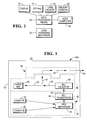
- Fig. 3 is a schematic representation of a cash dispensing mechanism according to the invention having a rear loading configuration;
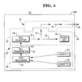
- Fig. 4 is a schematic representation of a cash dispensing mechanism according to the invention having a front loading configuration;
- Fig. 5 is a schematic representation showing a stage in the assembly of the cash dispensing mechanism of Fig. 3 or Fig. 4;
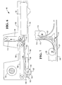
- Fig. 6 is a part sectional side elevational view of a core module of the cash dispensing mechanism of either Fig. 3 or Fig. 4;
- Fig. 7 is an enlarged side elevational view of a two position divert gate used in the core module of Fig. 6;
- Fig. 8 is a further side elevational view of the core module of Fig. 6, additionally showing part of the drive mechanism for the core module;
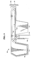
- Fig. 9 is a part sectional side elevational view of a spray dispensing upper unit of the cash dispensing mechanism of Fig. 3; and
- Fig. 10 is a further side elevational view of the upper unit of Fig. 9, additionally showing part of the drive mechanism for the upper unit.
-
- Referring first to Figs. 1 and 2 of the accompanying drawings, an
ATM 10 comprises adisplay 12 for displaying user information, akey pad 14 for inputting data, acard reader 16 for receiving a user identity card via acard slot 18, acash dispensing mechanism 20 for dispensing currency bills stored in themechanism 20 to a user during a transaction, via aslot 22, areceipt printer 24 for printing a receipt acknowledging a transaction made by a user and for issuing the receipt to the user via aslot 26, and data processing means 28 to which thedisplay 12, thekey pad 14, thecard reader 16, thecash dispensing mechanism 20 and thereceipt printer 24 are connected. - To make a withdrawal, a user inserts his identification card in the
card slot 18 of theATM 10. Data contained in a magnetic strip on the card is read by thecard reader 16 and transmitted by the data processing means 28 to ahost computer 30. The user identifies himself by entering his personal identity number via thekey pad 14. If thehost computer 30 authorizes the card then the user can proceed with his withdrawal by first entering details of the transaction, e.g. the amount of the withdrawal by means of thekey pad 14. - Referring now to Fig. 3, a
cash dispensing mechanism 20 having a rear loading configuration is shown. Thiscash dispensing mechanism 20 comprises a safe 40a inside which are housed alower unit 42 and anupper unit 44. The safe 40a is mounted in a housing 45 (see Fig. 1) of theATM 10. Thelower unit 42 has lower andupper sections lower section 46 of thelower unit 42 are mountedcurrency cassettes 50 which are associated with aconventional pick mechanism 52. It should be understood that theupper unit 44 is mounted on thelower unit 42 with a selected orientation relative to thelower unit 42 determined by the fact that thecash dispensing mechanism 20 has a rear loading configuration. - When a request for a cash withdrawal is made and approved, the data processing means 28 (see Fig. 2) causes the
pick mechanism 52 to pick bills in a known manner from at least onecassette 50. Each bill is picked singly and the bills are individually passed along a feed path (indicated by arrow 54) by conventional bill transport means 55 included in thelower section 46. The feed path takes the bill from thelower section 46 to aconventional bill validator 58 in theupper section 48. If thebill validator 58 accepts the bill then the bill is first transported along ahorizontal feed path 60 and is then transported vertically out of thelower unit 42 and into theupper unit 44 along afeed path 61. If thevalidator 58 does not accept the bill (e.g. if the bill is a multiple bill) then the bill is rejected and directed into apurge bin 62 via ahorizontal feed path 63 which is a continuation of thefeed path 60. The bills transported vertically out of thelower unit 42 are transported through theupper unit 44 via afeed path 64 where the bills are delivered to the user via aslot 65 in the safe 40a and via the delivery slot 22 (see Fig. 1) in the housing of theATM 10. As will be explained in more detail later, depending on the configuration of theupper unit 44, the bills are either stacked and delivered to the user as a bunch, or are delivered to the user one by one. - The safe 40a has a
door 66 on its rear side (i.e. the side opposite the front of the ATM 10) for enabling access to thecurrency cassettes 50 and thepurge bin 62. - Referring to Fig. 4, a
cash dispensing mechanism 20 having a front loading configuration is shown. The construction of thisfront loading mechanism 20 is the same as that of therear loading mechanism 20 shown in Fig. 3, except for the following differences. Firstly, theupper unit 44 is mounted on thelower unit 42 with an orientation which is rotated through 180° in relation to the first orientation shown in Fig. 3. Secondly, thedoor 66 of the safe 40b for enabling access tocassettes 50 and thepurge bin 60 is on the front side of the safe 40b (i.e. the side corresponding to the front of the ATM 10), and theexit slot 65 is in thedoor 66. - Referring to Fig. 5, it is shown how the assembly of the lower and
upper units cradle 80 is fixed to the underside of the roof of the safe 40a or 40b. The assembly of the lower andupper units framework 82. Twoslides 84 respectively provided on the sides of theframework 82 respectively slidably engage in two channels provided in thecradle 80, whereby theassembly - Referring to Fig. 6, the
upper section 48 of thelower unit 42 is shown in detail. Thisupper section 48 will hereinafter be referred to as thecore module 48. - The
core module 48 includes a pair of cooperating roller units 100,102 each comprising a series of individual rollers spaced along arespective shaft 103. The pair of roller units 100,102 receive and feed bills which have been transported upwardly from thelower section 46 by the transport means 55. Curvedend sections 104 of ahorizontal skid plate 106 are interspersed with the individual rollers of theroller unit 102. The leading edge of each bill which is received and fed by the roller units 100,102 of thecore module 48 is guided by guide means (not shown) into contact with abelt unit 108 which is disposed immediately above, and in cooperative engagement with, theskid plate 106. The bill is then pressed against theskid plate 106 by thebelt unit 108 and is transported by thebelt unit 108 past theconventional bill validator 58 to a known two positiondivert gate 112. If the bill is accepted by thevalidator 58, then thedivert gate 112 directs the bill into theentry throat 113 of a further transport means comprising a vertically extendingskid plate 114 and abelt unit 116 which is in cooperative engagement with theskid plate 114. Thebelt unit 116 presses the bill against theskid plate 114 and transports the bill upwardly out of theunit 42 and into theunit 44. If the bill is not accepted by thevalidator 58 then it is directed by thedivert gate 112, under the control of the data processing means 28, into thepurge bin 62. Thebelt unit 116 runs slightly faster than thebelt unit 108 to aid the bill change its direction of transport. Both belt units 108,116 are driven by areversible DC motor 118 operation of which is controlled by the data processing means 28. It should be understood that each of the belt units 108,116 comprises a plurality of endless belts extending around two sets of support pulleys, the pulleys of each set being spaced apart along a common shaft. One set of pulleys of eachbelt unit - If there is a power failure while a bill is present between the
vertical skid plate 114 and thebelt unit 116, then the divertgate 112 can be set to direct the bill into thepurge bin 62 when power is restored. - Referring to Fig. 7, the two position divert
gate 112 comprises two flippers 122,124 which are in the positions shown in solid outline when thegate 112 is set to direct bills from thehorizontal skid plate 106 andbelt unit 108 to thevertical skid plate 114 andbelt unit 116. The flippers 122,124 are in the positions shown in chain outline when thegate 112 is set to direct a bill into thepurge bin 62, either from the transport means comprising thehorizontal skid plate 106 and thebelt unit 108, or from the transport means comprising thevertical skid plate 1 14 and thebelt unit 116. - Referring to Fig. 8, drive for the belt units 108,116 is provided by the
motor 118 via timingbelts 130 which are mounted around, and are supported by,gear wheels 132. Thegear wheels 132 are respectively mounted on the shaft of themotor 118 and on the shafts on which the support pulleys 134 of the belt units 108,116 are mounted. Timing belts are known types of belts which have grooves on them which prevent slipping and which engage with the teeth of the associated gear wheels. Thus, onetiming belt 130 transmits drive from themotor 118 to drivepulleys 134 at one end offirst belt unit 108. Asecond timing belt 130 connects together the twogear wheels 132 respectively associated with the two ends of thefirst belt unit 108. Athird timing belt 130 connects together the twogear wheels 132 respectively associated with the two ends of thesecond belt unit 116. Drive from the timing belt and gear system associated with thebelt unit 108 is transmitted to the timing belt and gear system associated with thebelt unit 116 via further gears (not shown), whereby, as previously mentioned, thebelt unit 116 is driven at a somewhat higher speed than thebelt unit 108. A gear system which includes anidler gear 136 and which is operatively coupled to the timing belt and gear system associated with thebelt unit 108 enables themotor 118 to drive thepick mechanism 52 in thelower section 46 of thelower unit 42 of thecash dispenser mechanism 20. - The
core module 48 has been described as a separate unit and can be separately manufactured from the rest of thelower unit 42 before being attached to it. Alternatively, the wholelower unit 42 incorporating the features of thecore module 48 could be manufactured as one complete unit. - Referring to Fig. 9, the
upper unit 44 of a rear loading spray dispensingcash dispensing mechanism 20 is shown in detail. - This
upper unit 44 includes ahorizontal skid plate 160 which is cooperatively associated with a horizontally extendingbelt unit 162 disposed immediately above theskid plate 160. In a similar manner to thebelt units belt unit 162 comprises a plurality of individual endless belts which extend around, and are supported by, two sets of pulleys. The leading edge of a bill transported upwardly from thecore unit 48 makes contact with thebelt unit 162. Thebelt unit 162 is driven at a slightly faster speed than thesecond belt unit 116 of thecore module 48 in order to change the direction of travel of the bill. Acurved guide 166 also helps to direct the bill. The bill is pressed against theskid plate 160 by thebelt unit 162 and is transported out of theupper unit 44 through theslot 65 in the safe 40a and via the exit slot 22 (Fig. 1) of the housing of theATM 10 and into a tray (not shown) for collection by the user. A conventional shutter means (not shown) controlled by the data processing means 28 blocks theexit slot 22 when bills are not being presented to a user. - If there is a power failure, it is possible that a bill may be present between the
belt unit 162 and thehorizontal skid plate 160 at the time of the power failure. On restoring power, the data processing means 28 reverses the operation of the DC motor 118 (see Fig. 10), and hence the direction of movement of thebelt unit 162, for a short period of time, so that any bill present between thebelt unit 162 and theskid plate 160 is transported away from theslot 65 and into apurge bin 170 which is located adjacent that end of theupper unit 44 remote from theslot 65. - Referring to Fig. 10, a
timing belt 180 andgear wheels 182, which are respectively operatively associated with theDC motor 118 and the drive pulley set of thebelt unit 162, serve to transmit drive from theDC motor 118 to thebelt unit 162. - For a front loading spray dispensing
cash dispensing mechanism 20, in contrast with a rear loading spray dispensingcash dispensing mechanism 20, theupper unit 44 is simply rotated through 180° relative to thelower unit 42 prior to attachment to thelower unit 42. - The
upper unit 44 is detachably mounted on thelower unit 42. Thelower unit 42 is provided with first and second location means 190 (see Figs. 6, 8 and 10) which respectively cooperate with third and fourth locating means 191 (see Figs. 9 and 10) for locating theupper unit 44 relative to thecore module 48 in the supporting framework 82 (see Fig. 5). A conventional clamp (not shown) fits between each pair of cooperating locating means 190,191 to hold the lower andupper units vertical feed path 61 of bills from thelower unit 42 to theupper unit 44, so as to enable interchangeability between front and rear loading configurations. Note that alonger timing belt 180 is used to transmit drive from theDC motor 118 to thebelt unit 162 of theupper unit 44 of a front loading spray dispensingcash dispensing mechanism 20, and that agear 182 would be provided at either end of the drive pulley set of thebelt unit 162 so that the construction of theupper unit 44 is essentially the same for both front and rear loading spray dispensing cash dispensing mechanisms. - A spray dispensing cash dispensing mechanism in accordance with the invention has the advantage that it incorporates the same
lower unit 42 regardless of whether the mechanism has a rear loading or a front loading configuration. Thus a considerable saving in manufacturing costs is achieved. Moreover, by including many standard features such as thevalidator 58 and thepurge bin 62 in thelower unit 42, the construction of theupper unit 44 is simplified. By virtue of such simplification, essentially the same upper unit is used for both the rear access and front access spray delivery type of unit, enabling further savings in manufacturing costs to be achieved. - Another advantage of a cash dispensing mechanism in accordance with the invention is that, if an upper unit requires replacement, it is a simple matter to detach the upper unit from the lower unit and replace the original one by a new one.
Claims (9)
- A sheet dispensing mechanism (20) characterised by:a housing (40a,40b) having a sheet dispensing port (65) via which sheets are dispensed to a user;a first unit (42) mounted inside the housing and including a sheet storage unit (50), a picking mechanism (52) for picking sheets one by one from the sheet storage unit, and a first transport mechanism (55,106,108) for transporting sheets from the picking mechanism; anda second unit (44) which is mounted on the first unit (42) within the housing in one of two possible positions depending on whether the dispensing mechanism has a front loading or a rear loading configuration;the second unit being arranged to receive sheets transported upwardly from the first unit, and including a second transport mechanism (160,162) for transporting sheets received from the first unit to the sheet dispensing port (65); andthe first unit (42) including a sheet checking mechanism (58) through which sheets transported from the picking mechanism by the first transport mechanism are passed, a divert mechanism (112) for directing sheets rejected by the sheet checking mechanism to first reject means (62), and a third transport mechanism (114,116) for transporting sheets accepted by the sheet checking mechanism upwardly from the first unit to the second unit at a single transfer station, regardless of whether the dispensing mechanism has a front or rear loading configuration; andthe second transport mechanism (160,162) being arranged to transport sheets individually from the first unit to the sheet dispensing port.
- A sheet dispensing mechanism according to claim 1, characterised in that the third transport mechanism (114,116) is arranged to transport sheets from the first unit (42) in a substantially vertical direction.
- A sheet dispensing mechanism according to claim 1 or 2, characterised in that the first unit (42) has first and second locating means (190), and the second unit (44) has third and fourth locating means (191) which are arranged to cooperate with the first and second locating means for the purpose of locating the second unit relatively to the first unit, the first and second locating means and the third and fourth locating means being symmetrically positioned with respect to the transport path of sheets from the first unit.
- A sheet dispensing mechanism according to claim 1, 2 or 3, characterised in that the first unit includes a motor (118) arranged to drive the first, second and third transport mechanisms.
- A sheet dispensing mechanism according to claim 4, characterised in that a belt arrangement (180) is used to transmit drive from the motor (118) to the second transport mechanism (162), the length of the belt arrangement being dependent on whether the sheet dispensing mechanism has a front or rear loading configuration.
- A sheet dispensing mechanism according to any preceding claim, characterised in that the second unit (44) is detachably mounted on the first unit (42).
- A sheet dispensing mechanism according to any preceding claim, characterised by a second reject means (170) for receiving any sheet which is present in the second transport mechanism (160,162) at the time of a power failure and which is subsequently transported into the second reject means by the second transport mechanism following a resumption of power.
- A sheet dispensing mechanism according to any preceding claim, characterised in that the second transport mechanism comprises a continuous belt arrangement (116) co-operating with a flat surface (114), whereby individual sheets are transported between the continuous belt arrangement and the flat surface.
- A sheet dispensing mechanism according to any preceding claim incorporated in an automated teller machine (ATM) (10) for dispensing currency to an ATM user via the dispensing port (65) in the housing (40a,40b) characterised in that the sheet storage unit comprises at least one removable currency cassette (50), the second unit (44) is mounted on the first unit (42) within the housing in one of two possible positions depending on whether the ATM has a front loading or a rear loading configuration, the sheet checking mechanism is a currency validator (58) through which currency transported from the picking mechanism (52) by the first transport mechanism (55,106,108) is passed, the divert mechanism (112) is arranged to direct currency rejected by the currency validator (58) to the associated reject means (62), and the third transport mechanism (114,116) is arranged to transport currency accepted by the currency validator upwardly from the first unit to the second unit (44) at a single transfer station, regardless of whether the ATM has a front or rear loading configuration.
Applications Claiming Priority (2)
| Application Number | Priority Date | Filing Date | Title |
|---|---|---|---|
| GBGB9812839.0A GB9812839D0 (en) | 1998-06-16 | 1998-06-16 | Sheet dispensing mechanism |
| GB9812839 | 1998-06-16 |
Publications (2)
| Publication Number | Publication Date |
|---|---|
| EP0965953A1 true EP0965953A1 (en) | 1999-12-22 |
| EP0965953B1 EP0965953B1 (en) | 2006-10-25 |
Family
ID=10833761
Family Applications (1)
| Application Number | Title | Priority Date | Filing Date |
|---|---|---|---|
| EP99304595A Expired - Lifetime EP0965953B1 (en) | 1998-06-16 | 1999-06-14 | Sheet dispensing mechanism |
Country Status (8)
| Country | Link |
|---|---|
| US (1) | US6241150B1 (en) |
| EP (1) | EP0965953B1 (en) |
| JP (1) | JP4274395B2 (en) |
| BR (1) | BR9902271A (en) |
| DE (1) | DE69933732T2 (en) |
| ES (1) | ES2273459T3 (en) |
| GB (1) | GB9812839D0 (en) |
| ZA (1) | ZA993985B (en) |
Cited By (2)
| Publication number | Priority date | Publication date | Assignee | Title |
|---|---|---|---|---|
| EP1736937A1 (en) * | 2005-06-13 | 2006-12-27 | Nautilus Hyosung Inc. | Cash withdrawing apparatus of an automated teller machine |
| CN1854039B (en) * | 2005-04-27 | 2010-06-09 | 纳蒂卢斯晓星公司 | Apparatus of withdrawing cash from cash transaction machine |
Families Citing this family (6)
| Publication number | Priority date | Publication date | Assignee | Title |
|---|---|---|---|---|
| JP4135238B2 (en) | 1998-12-08 | 2008-08-20 | 日立オムロンターミナルソリューションズ株式会社 | Banknote deposit and withdrawal machine |
| GB2365610A (en) * | 2000-08-02 | 2002-02-20 | Ncr Int Inc | Self-service terminal |
| GB0130480D0 (en) * | 2001-12-20 | 2002-02-06 | Ncr Int Inc | Self service terminal |
| US20140012753A1 (en) | 2012-07-03 | 2014-01-09 | Bank Of America | Incident Management for Automated Teller Machines |
| US11328551B2 (en) * | 2018-07-20 | 2022-05-10 | Diebold Nixdorf Incorporated | Modular automated transaction machine |
| US11514762B2 (en) * | 2020-06-05 | 2022-11-29 | Hyosung TNS Inc. | Automated teller machine |
Citations (2)
| Publication number | Priority date | Publication date | Assignee | Title |
|---|---|---|---|---|
| US4936564A (en) * | 1988-11-03 | 1990-06-26 | Ncr Corporation | Sheet handling apparatus |
| US5240368A (en) * | 1989-12-04 | 1993-08-31 | Diebold, Inc. | Sheet handling apparatus |
Family Cites Families (2)
| Publication number | Priority date | Publication date | Assignee | Title |
|---|---|---|---|---|
| DE3216830C2 (en) * | 1981-05-09 | 1985-11-07 | Laurel Bank Machines Co., Ltd., Tokio/Tokyo | Banknote input / output device |
| JPS5810265A (en) | 1981-07-10 | 1983-01-20 | Toshiba Corp | Automatic transaction device for currency |
-
1998
- 1998-06-16 GB GBGB9812839.0A patent/GB9812839D0/en not_active Ceased
-
1999
- 1999-06-02 US US09/324,630 patent/US6241150B1/en not_active Expired - Lifetime
- 1999-06-14 EP EP99304595A patent/EP0965953B1/en not_active Expired - Lifetime
- 1999-06-14 ES ES99304595T patent/ES2273459T3/en not_active Expired - Lifetime
- 1999-06-14 DE DE69933732T patent/DE69933732T2/en not_active Expired - Lifetime
- 1999-06-15 BR BR9902271-0A patent/BR9902271A/en not_active IP Right Cessation
- 1999-06-15 ZA ZA9903985A patent/ZA993985B/en unknown
- 1999-06-16 JP JP20509999A patent/JP4274395B2/en not_active Expired - Lifetime
Patent Citations (3)
| Publication number | Priority date | Publication date | Assignee | Title |
|---|---|---|---|---|
| US4936564A (en) * | 1988-11-03 | 1990-06-26 | Ncr Corporation | Sheet handling apparatus |
| US5240368A (en) * | 1989-12-04 | 1993-08-31 | Diebold, Inc. | Sheet handling apparatus |
| US5342165A (en) * | 1989-12-04 | 1994-08-30 | Diebold, Incorporated | Sheet handling apparatus |
Cited By (5)
| Publication number | Priority date | Publication date | Assignee | Title |
|---|---|---|---|---|
| CN1854039B (en) * | 2005-04-27 | 2010-06-09 | 纳蒂卢斯晓星公司 | Apparatus of withdrawing cash from cash transaction machine |
| CN101540076B (en) * | 2005-04-27 | 2010-10-27 | 纳蒂卢斯晓星公司 | Apparatus of drawing bills in a cash transaction machine |
| EP1736937A1 (en) * | 2005-06-13 | 2006-12-27 | Nautilus Hyosung Inc. | Cash withdrawing apparatus of an automated teller machine |
| US7624977B2 (en) | 2005-06-13 | 2009-12-01 | Nautilus Hyosung Inc. | Apparatus of withdrawing cash from cash transaction machine |
| CN1881268B (en) * | 2005-06-13 | 2010-08-11 | 纳蒂卢斯晓星公司 | Cash withdrawing apparatus of an automated teller machine |
Also Published As
| Publication number | Publication date |
|---|---|
| DE69933732D1 (en) | 2006-12-07 |
| JP4274395B2 (en) | 2009-06-03 |
| JP2000099800A (en) | 2000-04-07 |
| ZA993985B (en) | 2001-01-04 |
| EP0965953B1 (en) | 2006-10-25 |
| ES2273459T3 (en) | 2007-05-01 |
| DE69933732T2 (en) | 2007-10-04 |
| BR9902271A (en) | 2000-01-04 |
| US6241150B1 (en) | 2001-06-05 |
| GB9812839D0 (en) | 1998-08-12 |
Similar Documents
| Publication | Publication Date | Title |
|---|---|---|
| EP0965956B1 (en) | Banking machine with front and rear loading configurations | |
| EP1357069B1 (en) | Automated banking machine | |
| US8453820B2 (en) | Currency handling system having multiple output receptacles interfaced with one or more cash processing devices | |
| US4473157A (en) | Automatic bank note transaction apparatus | |
| US6276603B1 (en) | Sheet dispensing mechanism | |
| EP0965953B1 (en) | Sheet dispensing mechanism | |
| JP3888780B2 (en) | Banknote stacking equipment | |
| JP2914463B2 (en) | Banknote deposit / withdrawal device | |
| EP0627711B1 (en) | Bank note conveyance device in island of amusement machines | |
| US20220335768A1 (en) | Banknote deposit-withdrawal system and architecture | |
| JPS60123991A (en) | Coin processor | |
| JPH05324982A (en) | Note processor | |
| JP2995261B2 (en) | Automatic transaction machine central processing system | |
| JP2695253B2 (en) | Charge settlement device | |
| JPH0632916Y2 (en) | Card issuing device | |
| JP2834958B2 (en) | Portable housing and securities handling equipment | |
| JP2503012B2 (en) | Automated teller machine | |
| JP2020086765A (en) | Coin storage part, coin processor, and automatic transaction device | |
| JPS60122637A (en) | Sheets takein and sendoff device | |
| JPH04111677U (en) | Temporary accumulation mechanism of banknote processing equipment | |
| JPH03296891A (en) | Paper money receiving/paying device | |
| JPH087815B2 (en) | Automatic machine batch processing device | |
| JPS60123987A (en) | Currency processor | |
| JPH0826497A (en) | Automatic bill payment device | |
| JPS63228394A (en) | Automatic transactor |
Legal Events
| Date | Code | Title | Description |
|---|---|---|---|
| PUAI | Public reference made under article 153(3) epc to a published international application that has entered the european phase |
Free format text: ORIGINAL CODE: 0009012 |
|
| AK | Designated contracting states |
Kind code of ref document: A1 Designated state(s): DE ES FR GB IT |
|
| AX | Request for extension of the european patent |
Free format text: AL;LT;LV;MK;RO;SI |
|
| 17P | Request for examination filed |
Effective date: 20000623 |
|
| AKX | Designation fees paid |
Free format text: DE ES FR GB IT |
|
| GRAP | Despatch of communication of intention to grant a patent |
Free format text: ORIGINAL CODE: EPIDOSNIGR1 |
|
| GRAS | Grant fee paid |
Free format text: ORIGINAL CODE: EPIDOSNIGR3 |
|
| GRAA | (expected) grant |
Free format text: ORIGINAL CODE: 0009210 |
|
| AK | Designated contracting states |
Kind code of ref document: B1 Designated state(s): DE ES FR GB IT |
|
| PG25 | Lapsed in a contracting state [announced via postgrant information from national office to epo] |
Ref country code: IT Free format text: LAPSE BECAUSE OF FAILURE TO SUBMIT A TRANSLATION OF THE DESCRIPTION OR TO PAY THE FEE WITHIN THE PRE;WARNING: LAPSES OF ITALIAN PATENTS WITH EFFECTIVE DATE BEFORE 2007 MAY HAVE OCCURRED AT ANY TIME BEFORE 2007. THE CORRECT EFFECTIVE DATE MAY BE DIFFERENT FROM THE ONE RECORDED.SCRIBED TIME-LIMIT Effective date: 20061025 |
|
| REG | Reference to a national code |
Ref country code: GB Ref legal event code: FG4D |
|
| REF | Corresponds to: |
Ref document number: 69933732 Country of ref document: DE Date of ref document: 20061207 Kind code of ref document: P |
|
| REG | Reference to a national code |
Ref country code: ES Ref legal event code: FG2A Ref document number: 2273459 Country of ref document: ES Kind code of ref document: T3 |
|
| ET | Fr: translation filed | ||
| PLBE | No opposition filed within time limit |
Free format text: ORIGINAL CODE: 0009261 |
|
| STAA | Information on the status of an ep patent application or granted ep patent |
Free format text: STATUS: NO OPPOSITION FILED WITHIN TIME LIMIT |
|
| 26N | No opposition filed |
Effective date: 20070726 |
|
| REG | Reference to a national code |
Ref country code: GB Ref legal event code: 746 Effective date: 20090416 |
|
| REG | Reference to a national code |
Ref country code: FR Ref legal event code: PLFP Year of fee payment: 18 |
|
| REG | Reference to a national code |
Ref country code: FR Ref legal event code: PLFP Year of fee payment: 19 |
|
| REG | Reference to a national code |
Ref country code: FR Ref legal event code: PLFP Year of fee payment: 20 |
|
| PGFP | Annual fee paid to national office [announced via postgrant information from national office to epo] |
Ref country code: FR Payment date: 20180626 Year of fee payment: 20 |
|
| PGFP | Annual fee paid to national office [announced via postgrant information from national office to epo] |
Ref country code: DE Payment date: 20180627 Year of fee payment: 20 Ref country code: ES Payment date: 20180702 Year of fee payment: 20 Ref country code: IT Payment date: 20180621 Year of fee payment: 20 Ref country code: GB Payment date: 20180627 Year of fee payment: 20 |
|
| REG | Reference to a national code |
Ref country code: DE Ref legal event code: R071 Ref document number: 69933732 Country of ref document: DE |
|
| REG | Reference to a national code |
Ref country code: GB Ref legal event code: PE20 Expiry date: 20190613 |
|
| PG25 | Lapsed in a contracting state [announced via postgrant information from national office to epo] |
Ref country code: GB Free format text: LAPSE BECAUSE OF EXPIRATION OF PROTECTION Effective date: 20190613 |
|
| REG | Reference to a national code |
Ref country code: ES Ref legal event code: FD2A Effective date: 20200903 |
|
| PG25 | Lapsed in a contracting state [announced via postgrant information from national office to epo] |
Ref country code: ES Free format text: LAPSE BECAUSE OF EXPIRATION OF PROTECTION Effective date: 20190615 |